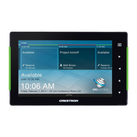
CRE I4GEN Guide


TECHNICAL DOCUMENTATION
2
A56V1_90020_D_EN
Table of cont ents
Introduction ................................................................................................................... 3
Caution Safety protections ............................................................................................................ 3
User's Notice ............................................................................................................................... 4
Package Contents ........................................................................................................................ 4
Environmental Protection Announcement ........................................................................................ 4
General Description ...................................................................................................................... 5
Specifications .............................................................................................................................. 6
Presentation ................................................................................................................................ 8
Installation .................................................................................................................... 9
Mechanical mounting .................................................................................................................... 9
USB Device Fixed Parts (Optional) ................................................................................................ 10
Wifi Antenna Installation (Optional) .............................................................................................. 11
Power supply ............................................................................................................................. 11
Network connection .................................................................................................................... 12
Communication ............................................................................................................ 13
Pre-requisite .............................................................................................................................. 13
Login/Connection ....................................................................................................................... 14
Functioning ...................................................................................................................... 17
Interface ................................................................................................................................... 17
Graphic objects .......................................................................................................................... 21
Numerical display .................................................................................................................. 21
Numerical display by variable number ..................................................................................... 21
Boolean display (LED) ............................................................................................................ 21
Bargraph .............................................................................................................................. 22
Gauge .................................................................................................................................. 23
3D pictures ........................................................................................................................... 24
Synchroscope ....................................................................................................................... 25
Popup .................................................................................................................................. 26
Alarm/Fault page ....................................................................................................................... 27
Visualization ......................................................................................................................... 27
Reset/Acknowledge ............................................................................................................... 28
Filters .................................................................................................................................. 28
About page ................................................................................................................................ 29
Home page ................................................................................................................................ 30
Supervision pages ...................................................................................................................... 31
Static configuration pages ........................................................................................................... 32
Modification by variable number ............................................................................................. 32
i4Gen Settings ........................................................................................................................... 34
Language ............................................................................................................................. 34
Theme ................................................................................................................................. 35
Screen ................................................................................................................................. 36
Date/Time ............................................................................................................................ 37
Connection ........................................................................................................................... 38
Network ............................................................................................................................... 41
Update ................................................................................................................................. 42
Preferences .......................................................................................................................... 43
System ................................................................................................................................ 43
Dimensions ..................................................................................................................... 44

TECHNICAL DOCUMENTATION
3
A56V1_90020_D_EN
In t r od uc tion
Caution Safety protections
Operate the product according to the correct installation steps and with great care to make sure
safety and comfort using experience. Please refer to the following safety instruction guide to avoid
danger of electric shock or fire. Abide by the previous safety instruction guide to use and maintain
the product and the hard disk to make sure of safe operating environment.
·Please follow the instruction manual for operation guide.
·The appropriate operating temperature ranges from -10...60°C.
·The operation humidity for this product is 5% to 80% RH.
·To avoid high temperature, please DO NOToverload the maximum power of the external power
supply while the system is consuming high voltage. Be aware of the maximum temperature
allowance of the power supply.
·See to it that the product is not working near the water.
·Always unplug power cable and other hardware cables from the system before cleaning.
·Apply only dry cloth for cleansing the product.
·Make sure that there is no heat source nearby when the product is working.
·Make sure that the thermal louver of the product is not blocked.
·Make sure to remove the power plug from the product when there is a thunder storm.
·Please remove the power plug from the product when you are not going to use the product for a long
time.
·Make sure to set up or use the product on a stable surface.
·Make sure not to drop the product or strike it by any means.
·Make sure not to move the product when the power is on.
·Make sure not to step on the power cables and other cables or rest anything in them.Be sure to
ground yourself to prevent static charge when installing any internal components. Use a grounding
wrist strap and place all electronic components in any static-shielded devices. Most electronic
components are sensitive to static electrical charge.
·Disconnect the power cord from the Panel PC unit prior to any installation. Be sure both the system
and all external devices are turned off. Sudden surge of power could ruin sensitive components.
Make sure the Panel PC unit is properly grounded. unit
·Do not open the system's back cover. If opening the cover for maintenance is a must, only a trained
technician is allowed to do so. Integrated circuits on computer boards are sensitive to static
electricity. To avoid damaging chips from electrostatic discharge, observe the following precautions:
·Before handling a board or integrated circuit, touch an unpainted portion of the system unit chassis
for a few seconds. This will help to discharge any static electricity on human body.
·When handling boards and components, wear a grounding wrist strap available from most electronic
component stores.
·Please contact qualified technician for maintenance or repair.
·Use only accessories and parts that are made by the qualified manufacturer.

TECHNICAL DOCUMENTATION
4
A56V1_90020_D_EN
User's Notice
Copyright of this manual belongs to the manufacturer. No part of this manual, including the products and
software described in it may be reproduced, transmitted or translated into any language in any form or by
any means without written permission of the manufacturer.
This manual contains all information required for the utilization of this product to meet the user's
requirements. But it will change, correct at any time without notice.
Manufacturer provides this manual “as is” without warranty of any kind, and will not be liable for any indirect,
special, incidental or consequential damages (including damages for loss of profit, loss of business, loss of
use of data, interruption of business and the like).
Products and corporate names appearing in this manual may or may not be registered trademarks or
copyrights of their respective companies, and they are used only for identification or explanation and to the
owner's benefit, without intent to infringe.
Package Contents
-1x i4Gen
-1x DC-DCAdapter 9 to 36VDC input for 12VDC output
-1x Power cord
-2x WIFI antenna
-4x Cabinet fixed parts
Environmental Protection Announcement
Do not dispose this electronic device into the trash while discarding. To minimize pollution and ensure
environment protection of mother earth, please recycle.

TECHNICAL DOCUMENTATION
5
A56V1_90020_D_EN
General Description
·10-point capacitive multi-touch
·Edge-to-edge narrow bezel design and fan-less cooling system
·Designed for easy wall mount, panel mount, and VESA mount installation
·A true flat, easy-to-clean front surface with an edge-to-edge design
·USB 3.0 ports support lock device
·IO ports designed for easy connection
·9...36V DC-input support, with EOS, OVP design
·On-board Intel® Braswell series SoC processor, with low power consumption never denies the high
performance
·On-board 4GB DDR3L 1333Mhz SO-DIMM
·On-board 1 x full-size Mini-PCIE slot
·On-board 1 x M.2 slot (M-key), type-2242 SATA interface for SSD device
·Support 2 x RJ-45 Gigabit LAN port and 1*external RJ-45 COM port
·1x2.4G WIFI module with support for 802.11 b/g/n WIFI communication
Additional Functions
·WiFi: The Mini PCI-E on-board socket in the board is integrated with a WIFI card (802.11 b/g/n) that can
act as a mini wireless modem when external antennas are connected. Different computers in the house
can build wireless connections through the Mini TOPS (Total Operations Processing System) and take
necessary data from it, thus reducing the complexity in network establishment.
·Giga LAN: The system is integrated with Gigabit LAN network controller with ACPI (Advanced
Configuration and Power Interface) management realizing efficient power management for the operating
system.
·USB 3.0: Experience fastest data transfers at 5Gb/s with USB 3.0 the new latest connectivity standard.
Built connect easily with next-generation components and peripherals, USB 3.0 transfers data 10 times
faster and backward compatible with previous USB2.0 components.
·CPU usage: The CPU Usage diagram shows a beautiful data curve that indicates a pretty low CPU
usage percentage for video playback of different formats. GPU performances are excellent as well.
·dB value: The design of the system takes into consideration the needed quiet operating environment in
the living room and the average dB value is below 26 under normal operation to ensure the tranquility
when you are absorbed in film watching.

TECHNICAL DOCUMENTATION
6
A56V1_90020_D_EN
Specifications
Display
Front Bazel IP65, NEMA 4 rugged protection, Full planar metal border
Display Type 10.1'' with LED backlight
Brightness (cd/m²) 400 nits
Display Color 16.2M
Resolution 1280 x 800 @ 60Hz
Viewing Angle (H/V) 170o / 170o
Pixel Pitch 0.1695 x 0.1695 mm
Aspect Ratio 16:10
Contrast Ratio 800:1
Response Time 30 ms
Touch Screen
Type Projected capacitive type
Active Range 257.10 x 159.66mm + 0.2mm
Transparency > 87%
Surface Hardness > 6H (JIS-5400)
Glass Haze Value > 3%
Main CPU Board
CPU Intel® Braswell series SoC CPU
System Memory Onboard 4GB DDR3L 1333MHz SO-DIMM
BIOS AMI 64Mb Flash ROM

TECHNICAL DOCUMENTATION
7
A56V1_90020_D_EN
I/O System
Icon Name Quantity Description
Power Button 1 Press to turn on/ off the system.
DC-in Power
Connector 1For user to connect compatible terminal power block
to
provide power supply for the system.
HDMI Port 1 To connect display device that support HDMI
specification. (Not used).
USB 3.0 Port 4 To connect USB keyboard, mouse or other devices
compatible with USB specification. USB 3.0 ports
supports upto 5Gbps datatransfer rate.
RJ-45 LAN Port 2 This connector is standardRJ- 45 LANjack for
Network
connection.
RJ-45 COM Port 1 This connector is standardRJ- 45 COM jack for serial
console port connection. (Not used).
GPIO
Connector-Male 1This connector is aRJ-45 COM port for console
function. (Not used).
Environment
Operating temperature ranges -10...60°C
Humidity 5% to 80% (Relative Humidity)

TECHNICAL DOCUMENTATION
8
A56V1_90020_D_EN
Presentation
i4Gen is a customer interface made by CRE to offer users a complete management of new CRE controllers.
The unit hardware is a multi-touch screen color display develop for harsh environment and industrial areas,
providing access to all controller's data for control, measurement and configuration.
Thanks to an embedded TeamViewer© License, it will be possible to access remotely to the i4Gen for
support, remote control or fleet management.
i4Gen License free software provide also the capability for each user to use the interface from any platform
(PC, tablets) in order to configure, customize and program CRE controllers online or offline.
Control and Management
Direct display
i4Gen is able to display information from 1 controller in direct Ethernet connection and shows a basic
overview of the power plant by using controller CANbus data when applicable.
SCADA display
i4Gen can be used as a power plant display if connected on an Ethernet HUB accessing to each controller
with the Modbus TCP network. In SCADA mode the direct display of any of the controller is available and a
SCADA page allows the user to change the displayed controller.
Multi-user display
Several i4Gen can also be securely connected by Ethernet hub a single controller (or a group of
controllers), for redundancy application, multi-level access or long-distance monitoring panel.
Eventsdisplayed/recorded
An innovative feature turns major alarms and faults into 3D graphical object display, to warn operator about
an important event and facilitate immediate diagnosis (ex: coolant tank lights up in red in case of coolant
temp fault or in orange in case of coolant temp alarm).
An event alarm/fault recorder is also available on a dedicated display page, indicating timestamps, status,
acknowledgment, and corresponding variable; the event page can be filtered for diagnosis and investigation
of selected variables.
Compatibility
i4Gen is compatible with these controller versions :
- GENSYS2.0 (starting v5.01). Beware, v5.04 is not supported.

TECHNICAL DOCUMENTATION
9
A56V1_90020_D_EN
In stallation
Mechanical mounting
Install i4Gen position at eye level and at brightness-less location.
Frame cut-out (hxl): 160x242mm (6.3x9.5in).
Chassis Fixed Parts
1. Insert corresponding edges of the fixed part into the slots until
them matched.Make sure the fix part is installed in the way the
photo shows, with protruding tips upwards.
2. The models that support this fixing mode have pairs of slots
reserved on both sides of the system. User can choose the height or
position of installing spot.
3. Insert corresponding edges of the fixed part into the slots until
them matched. Tightening up the screw so that the fixed part can be
fitted into the slots tightly. Install other fixed parts to the system in
the same way.

TECHNICAL DOCUMENTATION
10
A56V1_90020_D_EN
USB Device Fixed Parts (Optional)
1. The USB device fixed accessories include Part-A, Part-B and 2 sets of screws of different size.
2. Align the screw hole of Part-A to corresponding screws hole from IO panel of the chassis, and then lock
Part-A to the panel with the bigger screw, as the photo shows.
3. Insert the cable end of USB device you wish to connect to USB port of the chassis, as the photo shows.
4. Insert Part-B into corresponding slot of the Part-A and choose the installing length by adjusting the screw
holes from both parts. Make sure the screw holes from both parts matched and the USB cable fitted into the
reserved slot of Part-B, as the photo shows.
5. Turn over the system on a flat operation platform and lock Part-B to Part-A by tightening the 2 screws in
the marked spots.
6. Fastening the USB device cable by tightening up the other screw in the marked spots.

TECHNICAL DOCUMENTATION
11
A56V1_90020_D_EN
Wifi Antenna Installation (Optional)
Screw the two antenna on the antenna heads connectors
Power supply
By default, power supply connector is connected to the AC-DC adapter. If you want to supply your i4Gen
with a battery, please disconnect theAC-DC adapter wires from the connector and connect the battery wires
to the connector instead.
9...36VDC input Euro terminal power jack
1. Turn off your power supply.
2. Connect the male supply connector to the female supply connector on the
chassis.
3. Tighten the two connector fixing screws.
4. Turn on your power supply.
5. The i4Gen starts automatically when the power is turned on.
6. To turn off the i4Gen, press the On/Off power button on the i4Gen chassis.

TECHNICAL DOCUMENTATION
12
A56V1_90020_D_EN
Network connection
There are several possible connection types between the i4Gen and the controller.
Direct Connection
·Connect the Ethernet port (RJ45-LAN) labeled "module" of the i4Gen to the Ethernet port of the
controller.
Connection Via a Switch
·Connect the Ethernet port (RJ45-LAN) labeled "module" of the i4Gen on one of the switch's Ethernet
ports.
·Connect the Ethernet port of the controller on one of the switch's Ethernet ports.
You can connect up to 32 controllers on one switch. You will then be able to supervise each controller, in
turn, using i4Gen. To facilitate connection switching from one controller to another, the i4Gen has a
"Switch connect" function (see "Switch connect" section in the Connection section of the settings page).

TECHNICAL DOCUMENTATION
13
A56V1_90020_D_EN
Commun ic ation
Pre-requisite
To be able to establish communication between the i4Gen and the controller, the network addresses of both
devices must be configured:
·The i4Gen network configuration can be done from the i4Gen "Network" settings page (see Network
chapter).
·The controller network configuration can be done from the controller front panel or controller website or
via CRE Config software.
If the i4Gen and the controller are connected directly, the network configuration of both devices has to be
compatible:
·The IP address by default of the i4Gen is: 192.168.11.50
·The IP address by default of CRE Technology controllers is: 192.168.11.1
These two addresses are in the same subnet (first 3 identical numbers), the i4Gen and the controller can
communicate together.

TECHNICAL DOCUMENTATION
14
A56V1_90020_D_EN
Login/Connection
Press login/connection icon to open login/connection window.
i4Gen uses the classic password system of the CRE Technology modules for access
authorizations and parameter modification of the connected module.
Level Default password Rights Menu
0 None None Display and manual button
1 1 User settings All Menus
2CRE Technology distributor's
reserved Advanced settings All Menus
To connect to a module, you have to fill the following information:
·The IP address of the controller
·The Modbus port TCP of the controller
·The HTTP port of the controller
·The UDP port of the controller
·The corresponding log in password level
Once you have filled these information, push the button to connect and to log in
with the entered password level.

TECHNICAL DOCUMENTATION
15
A56V1_90020_D_EN
Note: Once the connection is established, i4Gen downloads the information (labels, accuracies, units) of
the modifiable variables.
Once logged in, you can change the login password level by changing the "Password" field and pressing
the button
Passwords are the same as those used to connect directly to the module via its front panel or embedded
website.
It is possible to disconnect by pressing the button .
When the connection to the controller is lost or a connection switch to another controller is done, the i4Gen
attempts to connect or reconnect to the remote controller for several seconds and then abandons after a
while.

TECHNICAL DOCUMENTATION
16
A56V1_90020_D_EN
During connection/re-connection attempts, the button is replaced by a
button to manually cancel the attempts.

TECHNICAL DOCUMENTATION
17
A56V1_90020_D_EN
Fun ctioning
Interface
The interface of the i4Gen allows to replace the front panel of CRE Technology modules and to offer a
better ergonomics in order to facilitate the supervision of our products.

TECHNICAL DOCUMENTATION
18
A56V1_90020_D_EN
Header
TOUCH ICONS
About page
Fault & Alarm menu (Status when there are no faults or alarms)
Supervision menu
Static configuration menu
Connection/Login menu
Settings menu
Home (Back to home page)
INDICATORS
Alarm: Blinking unacknowledged alarm, Static: alarm acknowledged and in progress
Fault: Blinking unacknowledged fault, Static: fault acknowledged and in progress
Module disconnected
Module connected + password level (id: 1)
Connection in progress / Reconnection after connection loss
Title and index of current opened page

TECHNICAL DOCUMENTATION
19
A56V1_90020_D_EN
Content
Footer
All footer buttons are only available when the i4Gen is connected:
TOUCH ICON
AUTO mode, colored in theme color when active
TEST mode, colored in theme color when active
MANUAL mode, colored in theme color when active
Give access to additional buttons for manual frequency/voltage control.
Colored in theme color when active
Increase frequency
Decrease frequency
Increase voltage
Decrease voltage
Start generator
Stop generator

TECHNICAL DOCUMENTATION
20
A56V1_90020_D_EN
INDICATORS
Generator number of current connected controller
Engine and Power states
Synoptic for configurations without Mains.
Breaker icon become a button only in manual mode.
Supplied elements are colored in green.
Synoptic for configurations with Mains.
Breaker icon become a button only in manual mode.
Supplied elements are colored in green.
Supervision Mode
In supervision mode, the footer gives access to :
·Control buttons of the controller.
·Specific information on the generator (number, engine status, power status).
·Synoptic of the installation.
Note: When the i4Gen is off-line, the control buttons from the footer cannot be used.
The i4Gen footer is dynamic and adapts to the controller configuration:
GENSYS2.0 in manual mode: control buttons are available.
GENSYS2.0 in automatic mode: control buttons are hidden
Configuration Mode
In configuration mode, the footer displays :
·The name of the page in use
·A button to send local changes to the controller
·A button to undo local changes
Other manuals for I4GEN
2
Table of contents
Other CRE Touchscreen manuals
