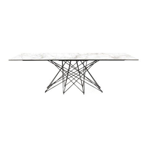
538W Rectangular Plank Extension Table Top
TOOLS REQUIRED: Phillips Screwdriver
BEFORE BEGINNING ASSEMBLY:
Check that the quantities of the parts received match those on parts list below.
A2 Table Top/Leaf Set . . . . . . . 1/1
B2 Left Front/Back Apron. . . . . . 2
(attached)
C2 Right Front/Back Apron . . . . 2
(attached)
D2
End
Apron . . . . . . . . . . . . . . 2
(attached)
FF Leaf Apron . . . . . . . . . . . . . . 2
PART QTY
SPECIAL INSTRUCTIONS
If a top or leaf panel should become cupped, do not be alarmed. The top was flat when it was manufactured.
It is a natural characteristic of wood in an unfinished state to cup from uneven moisture conditions. The
figure at the right shows an exaggerated view of what could happen. This only means that the convex
side has absorbed moisture, or the concave side has dried out.
Usually a cupped panel will equalize and straighten out if both sides are exposed to similar
conditions for a day or so.
1) Lay the Table Top and the Leaves (A2) face down on a clean protected surface. Make sure that the arrows
stamped on the table ends and leaves face each other. Pull sections slightly apart and glue Guide Pins (N)
into the predrilled holes. Make sure that the pins all face the same direction.
2) Starting from one end of the table, lay out the Lever Locks (K) over the pre-punched screw holes. All the
lever locks must face in the same direction on both sides of the table. Fasten the lever locks in place with
#6 x 5/8" Flat Head Screws (L). Slide the Leveler Plate (M) into the lever locks and fasten with #6 x 5/8"
Flat Head Screws (L) in predrilled holes.
3) The leaves and leaf aprons have been punched with matching letters (A/A, B/B, C/C, D/D) to assist in
positioning the Leaf Aprons in the proper locations. The leaves have been predrilled to aid in attaching the
aprons. Insert a #8 x 1¼" Pan Head Screw (H) through three holes in the Leaf Apron (FF) into the pre-
drilled holes in the Leaf (A2) and fasten securely. To increase support for the leaf aprons, fasten a Brass
Angle Brace (I) just to the left or right of the center hole of the aprons with #10 x 3/4" Brass Oval Head
Screws (J).
H #8 x 1¼" Pan Head Screw . 24
(some inserted)
I Brass Angle Brace . . . . . . . . . 2
J #10 x 3/4" Brass Oval
Head Screw . . . . . . . . . . . . . . 4
K Lever Lock . . . . . . . . . . . . . . . 4
L #6 x 5/8" Flat Head Screw
. . 16
(for Lever Lock and Leveler Plate)
M Leveler Plate . . . . . . . . . . . . . 4
N Guide Pin . . . . . . . . . . . . . . . . 6
O Table Slides (attached) . . . . . . 2
P #12 x 1¾" Pan Head Screw . .16
(inserted)
Q Leg Bracket (attached) . . . . . . 4
R #6 x 5/8" Flat Head Screw . .16
(inserted )
PART QTY PART QTY
FIG. 1
FIG. 2
N
KL
A2
A
H
FF
JI
H
H
A
A2
FIG. 3
K
M
L
N
A2A2A2
