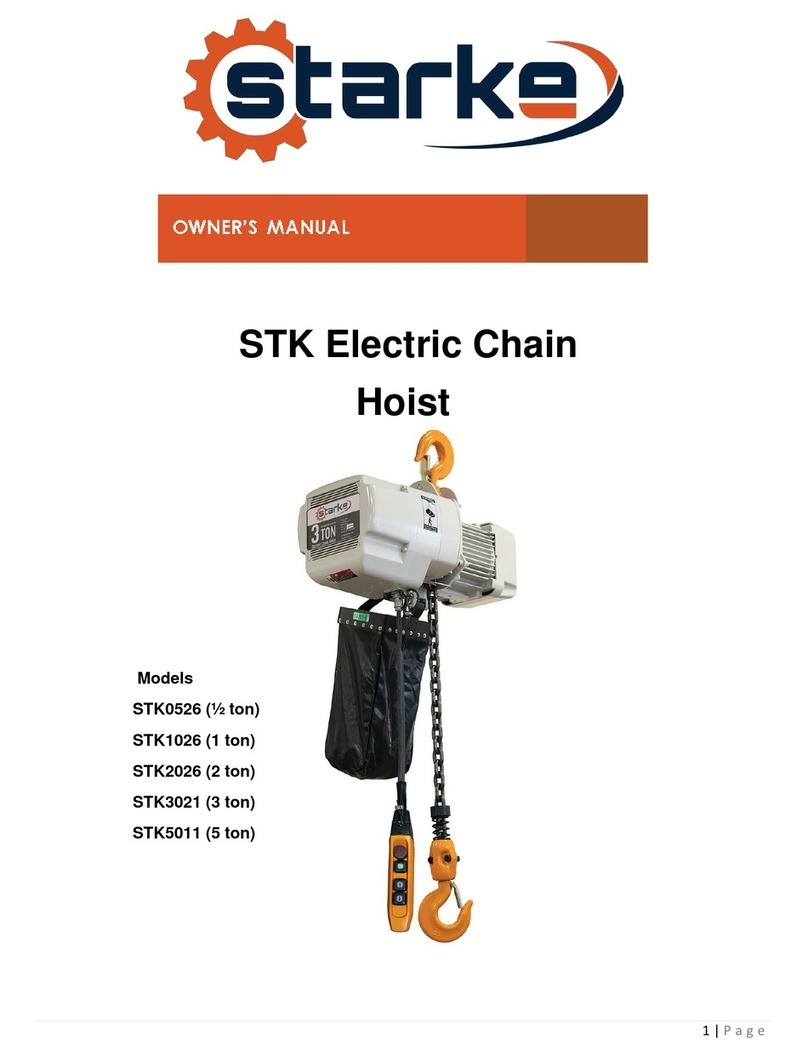
Starke STK Series User manual

STARKE “STK SERIES”
ELECTRIC CHAIN HOIST
OWNER’S MANUAL
STARKEAMERICA.COM

Safety First
Any hoisting equipment may have potential risks to cause
personal injuries or property damage.
If operators do not follow the proper operation instructions
and pay no attention to precaution,the occurrence of risks will
greatly increase.Thus,it is required that every operator should
read through and be familiar with the operation manual and
precautions before operation to ensure the safe operation.
If any part of the manual has the alarming signs as indicated
at the right and left and the part is underlined,it indicates that
the part is vital safety description or precaution.And operators
must fully followed,otherwise,it may endanger the operators or
others or property.
Hence,before operate electric chain hoist,
please read through the manual and precautions.

Content
Safety First
1 Preface -·
-· --·
-·
-·
- - ·
-·
-.. -· -.. -·
-·
-·
-.. -.. -· -.. -· -·
-· -· -.. -·
-.. -· -·
-·
-· -.. -·
-.. -· -·
-·
-· -· -·
-·
-1
2 Main specifications -· - - -.... ·· -- - ·· --·· ··· ---· - - ·- -· - - -· - - ·- -- - ·- --· 2
2.1 Table of specifications -- -·- -·- --- -·-··- --···-·-·- ··- --·-·-····------- 2
2.2 Machine degree and service life --...... -----·
-·-· - - ·-· -· -----..... - - -3
2.3 Safety devices -- --- ---- -- - - --- -----·------ -- - - --- - - - 5
2.4 Technical parameters of electric chain hoist ----· ... --····- ·- -... -...... -·- - - 5
2. 5 Electric trolley - - - - - - ·-· -----------· - - ··· - - - - - - ·-· -·· --· - - 7
3 Safety rules -· ---· -- - -· -·· -· - - · -· - - ·-· --· -· - - · - - -· -· -· -· -· -· -· -· ----- ----8
4 Installation --------------------·- - - -·-· --- ·· -·- ----- ----- 10
4.1 Unpack of Electric Chain Hoist - - -- - ---------- - - - -- - - - - - 10
4.2 Voltage ------- - - - - .... - - -----·
----·- - - - - - -·- .. --·
-... - - ·· 10
4.3 Installation of Electric Chain Hoist - - -- ----------- ------ - - - - - - -10
4.4 Installation of electric chain hoist with electric trolley ------· -------· 13
5 Operation - - - - - - - - -- - - - - - - - - - - -- - -- - ----------- --------------------·--·--·· 15
6 Maintenance and overhaul - - ---- - -- - ---- - - - - -- - - - ------· -16
6.1 Maintenance -------..... -· -..... -·- -·-· -..... ----· -·- - - - - ---- ..... --16
6.2 Overhaul -- - --- - --- - ---- - - - -------------- - - - --16
7 Wiring diagram - - - - --- - - - - - ------ - --- - -- - -------- - --- 20
8 Drawing and parts list ------- ---- - - --- ------ ------- - -- -- - ----24
9 Common problems and processing- - - - - - --- ---- -- - - - - - --- --- ---- -- 40
10 Instructions of using and inspecting for electric chain hoist - - -- ---- - - -- - - 41
1. Preface
The manual can assist you in correct installing operating and maintaining your
electric chain hoist,ensure your hoist to operate safely with the highest efficiency.
Before you use the hoist,please read through the manual to know about the
correct procedure and operation,as well as preventative maintenance to guarantee
you to have faithful and reliable service.
In order to provide the parts you need to replace in the shortest time,please
provide us with the following data when you contact us:
(1) Type of the hoist you purchased
(2) Product serial number of the hoist you purchased
( 3) Na me of the parts needed (it had better to attach
part description).
We believe you will find the electric chain hoist will work for you satisfactorily
for years.If you have any questions,please do not hesitate to contact us.
(Please ask the distributor to affix its seal)

2. Main specifications
2.1 Table of specifications
The specifications in the following table are applicable to all electric chain hoists.
Table 2.1 Specifications
Item Specification
Range of working humidity(%) 85 or below85
Range of working temperature( °
C) -20-+40
Hoist Ip54
Protection class
Push button Ip54
Power supply 3 phase,200-600V,50/60Hz
Single speed hoist 81
Noise degree(dB)
Double speed hoist 81
Limit working load Nominal diameter(mm) Chain Internal length(mm)
0.St 6.3 19
Chain 1t,2t,3t 7.1 21
specifications
1.St,2t,3t 10.0 30
2.St,3t,St,7.St 11.2 34
Remarks
(1) If your working temperature and humidity are out the range of the value in the table, please
ask your distributor for related data.
(2) Expected operation ways:The hoist is designed to vertically lift in normal atmosphere and
working conditions.
(3) The standard of noise degree is the value measured at 1 meter from the machine under the
normal operation.
2.2 Machine degree and service life
The service and safety of the electric chain hoist can be guaranteed only under the condition
that it is operated according to the following.
The design of the hoist conforms to lAm of FEM(Table 2.21)
The description is detailed in table 2.2
The average operation hours per day and total operation hours are calculated on the basis of
load distribution.
Table 2.2 Categories of machine degrees
Load types Definition Cubic meters Average operation hours per day(hours)
Value represented
The mechanism and
parts are frequently
l(light) under light load, and K:<::;0.50 :<::;2 2-4 4-8 8-16 :<::;16 >16
there is no max. load
other than exceptional
conditions.
The mechanism and
parts are frequently
2(middle) under light load, but 0.S0<K:<::;0.63 :<::;1 1-2 2-4 4-8 8-16 :<::;16
also under max. load
with low frequency.
The mechanism and
3(heavy) parts are frequently 0.63<K:<::;0.80 :<::;0.5 0.5-1 1-2 2-4 4-8 8-16
under middle and
heavy load.
The mechanism and
4 parts are frequently 0.80<K:<::;1.00 :<::;0.25 0.25-0.5 0.5-1 1-2 2-4 4-8
(Super-heavy) under max. or nearly
max. Load.
1Bm 1Am 2m 3m 4m Sm
llilll

I-I---------I---------
o 10 50
Operation time Load condition 1
-,---------,
0.4
100
I
-------I
0 50 100
Operation time Load condition 3
0.2
1-1-1-1--
0 16.7 33.3 50 100
Operation time Load condition 2
---,--.----------------, 0.8
1100
0
90
Operation time Load condition 4
Table2.21 Standard of lifting motor
Group Intermitted operation Continuous Operation
F.E.M ISO Cycles/h Starts/h ED(%) Operation cycle/min
1 DM Ml 15 90 15 7.5
1 CM M2 20 120 20 7.5
1 BM M3 25 250 25 15
1
AM M4 30 180 30 15
2M MS 40 240 40 30
3M M6 50 300 50 30
4M M7 60 360 60 60
SM MS 60 360 60 >60
2.3 Safety devices
( 1) Side magnetic braking device
It is a unique design which is characterized with the ability that
the brake acts immediately as soon as the electric power is cut off.
(2) Hooks and safety latch
The hook is hot forging with high tensile steel and heat treated to
meet the demands on strength and hardness.The operation safety
of the lower hook is ensured by its 360 ° degrees rotation and safety
latch.
(3) Anti-phase protecting device
It is special design to control the circuit not to work and protect the
electric motor from being burned in case of wiring error in the power
supply.
(4) Limit switch
It is installed where the weights is lifted on and off to make the motor
stop automatically so as to prohibit the chains from exceeding for safety.
(5) Emergency stop switch(optional)
The button is used to stop the hoist in emergency. It is red, mushroom-
shaped push button, located on the top of the push buttons. When the
button is pushed, the power supply to the equipped is cut off and the
button is locked automatically. Turn it in clockwise to release the button
and restart the hoist.
c::€J juoco corn
qi
6 points+
emergency switch
c::€J !uo co co q
1
4 points+
emergency switch
c:::( • (lQ
oaj
i
2 points+
emergency switch
llt-f
Iii
.1
2.4 Technical parameters of electric chain hoist
Capacity(ton)
0.5 1 1 1.5 2 2 2.5 3 3 3 5
Chain Fall
1 2 1 1 1 2 1 1 2 3 2
Remove Litre of Altitude
3/9 m
Chain Diameter(mm)
6.3 6.3 7.1
10 10
7.1 11.2 11.2
10
7.1 11.2
Lilting Speed(m/min)
6.8 3.4 6.6 8.8 6.6 3.3 5.4 5.4 4.4 2.2 2.7
Motor Power(kw)
0.75 0.75 1.5 3.0 3.0 1.5 3.0 3.0 3.0 1.5 3.0
Power Supply(V)
200-600
E.D.Rating(%)
40 40 40 40 40 40 40 40 40 40 40
7.5
3
11.2
1.8
3.0
40

A
A
D
:,:
__ __,
A
Capacity Unit(mm)
Chain fall (Ton) Chain
A B D E I J K L M N
1 0.5 455 566 266 285 165 <1>35 27 <1>34 25 17 17 6.3
1 1 520 627 302 300 176 <1>42 32 <1>41 32 24 24 7.1
2 1 490 566 266 285 165 <1>35 27 <1>41 32 24 24 6.3
1 1.5 640 733 343 430 265 <1>48 38 <1>49 40 28 28 10
1 2 640 733 343 430 265 <1>48 38 <1>49 40 28 28 10
2 2 705 627 302 300 236 <1>48 38 <1>49 40 28 28 7.1
1 2.5 685 733 343 430 265 cj>59 48 cj>59 48 34 34 11 .2
1 3 685 733 343 430 265 cj>59 48 cj>59 48 34 34 11 .2
2 3 790 733 343 430 320 cj>59 48 cj>59 48 34 34 10
3 3 820 627 302 350 205 cj>59 48 cj>59 48 34 34 7.1
2 5 870 733 343 430 325 <1>59 48 <1>60 48 42 42 11.2
Capacity Unit(mm)
Chain fall (Ton) Chain
A B D E K L N I J
p
1 0.5 525 566 266 300 165 <1>34 25 17 <1>26 90 164 6.3
1 1 520 627 302 320 176 <I> 41 32 24 <1>26 90 164 7.1
2 1 580 566 266 200 165 <I> 41 32 24 <1>26 90 164 6.3
1 1.5 610 733 343 450 265 <1>49 40 28 <I> 31 115 221 10
1 2 610 733 343 450 265 <1>49 40 28 <I> 31 115 221 10
2 2 685 627 302 320 236 <1>49 40 28 <I> 31 115 221 7.1
1 2.5 670 733 343 450 265 cj>59 48 34 cj>36 138 265 11 .2
1 3 670 733 343 450 265 cj>59 48 34 cj>36 138 265 11 .2
2 3 770 733 343 450 320 cj>59 48 34 cj>36 138 265 10
3 3 810 627 302 370 205 cj>59 48 34 cj>36 138 265 7.1
2 5 855 733 343 450 325 <1>60 48 42 <I> 41 157 304 11.2
...
Capacity
Chain fall (Ton) A
1 0.5 525 566
1 1 520 627
2 1 580 566
1 1.5 610 733
1
2 610 733
2 2 685 627
1
2.5 670 733
1
3 670 733
2 3 770 733
3 3 810 627
2 5 855 733
2.5 Electric trolley
R
0 0
0 •
0 0
s
Unit(mm)
B D E I K L N
266 285 165 <I> 31 <1>34 25 17
302 300 176 <I> 31 <1>41 32 24
266 285 165 <I> 31 <1>41 32 24
343 430 265 <1>36 <1>49 40 28
343 430 265 <1>36 <1>49 40 28
302 300 236 <1>36 <1>49 40 28
343 430 265 <1>43 <1>59 48 34
343 430 265 <1>43 cj>59 48 34
343 430 320 <1>43 cj>59 48 34
302 350 205 <1>43 cj>59 48 34
343 430 325 <1>54 cj>60 48 42
T
Table 2.5 Specifications of Electric Trolley(mm)
Capacity
s
Speed
(ton)
A B R
I-beam
T
(m/min)
(mm) 50Hz
0.5 315 212 142 52-153 231 11 or 21
1 315 212 142 52-153 231 llor21
2 325 220 142 82-178 231 llor21
3 340 250 142 100-178 231 llor21
5 400 291 142 100-178 231 11 or 21
7.5 400 291 142 100-178 230 11 or 21
Chain
w
u
RT
206 111 142 231 6.3
206 111 142 231 7.1
206 111 142 231 6.3
237 127 142 231 10
237 127 142 231 10
237 127 142 231 7.1
265 140 142 231 11.2
265 140 142 231 11.2
265 140 142 231 10
265 140 142 231 7.1
196 156 142 231 11.2
A
co
Motor Minimum Net
(Kw) radius of Weight
turn (Kg)
0.4 0.8 45
0.4 0.8 45
0.4 0.8 53
0.75 1.0 65
0.75 1.8 88
0.75 1.8 95

3.Safety rules
A
Danger
The hoist is not designed for supporting, loading persons .Any modification,
includes upgrade and lifting speed change or any hoist design change must
be done by original manufactory or qualified professional engineer.
A
Danger
It is forbidden to operate the hoist under the explosive environment.
(1) Person who have related training and experience can operate the hoist
(2) Before operation , please confirm the followings:
(a) To use the proper lifting rope .
(b) The location of the cable should be as indicated in the following diagram (fig.3.1)
and the safety latch must lock the hook correctly .
(c) To make sure the weights safe and firm ,then lift it
(3) The button must be operated stably and firmly
( 4) Try my best to avoid excessive inching operation .
(5) Be sure that the motor has been completely stopped before operating in the reverse direction.
(6) When finished operation , to keep the control cable and the lower hook vertically and statically.
(7) When lifting ,the weights must be kept balance .Never lift the weight which are not in balance .
(8) It is forbidden to drag the weights horizontally.(see Fig 3.2)
(9) It is forbidden to lift the weights by using the chain to bind the weights .(see Fig 3.3)
(10) When in operation, the operators must face and pay attention to the weights .Be sure not to
turn back to or overlook it .
BIi
(11) It is risky to lift the weights over the rated load capacity. And it should not be tried .
(12) Do not lift goods when the chain is twined .
(13) Regular inspection to ensure chain is in a good condition, if the chain is damaged, don't operate
hoist to lift the weights.
(Fig.3.1} (Fig.3.2} (Fig.3.3}
A
Warning
Never use the chain as a welding electrode
Warning
Never stand under
when lifting
(see Fig. 3.4)
(Fig.3.4}

4.Insta llation
lllill
4.1 Unpacking
After unpacking ,please check carefully to ensure the cable ,gearbox,
and motor shell are not damaged ,and check whether the number of
the following items is correct .Every hoist should be equipped with
the following standard accessories.
1.Chain bag One
2.Control cable 3 Meter
3. Push button One
4.2 Voltage
A
Note
If the voltage of power supply is over or less 10% than standard voltage
to operate hoist under the abnormal voltage will result in motor damage ,
hence , before operation , be sure to confirm whether the voltage of power
supply is within the standard range.
4.3 Installation
A
Warning
It is forbidden to link the power supply before the completion of installation
4.3.1 Before installing the hoist, please confirm the whole upper hook assembly
has been firmly assembled to the hoist body (ensure the chain connection
pin is installed properly).
Remarks :If
the hoist is equipped with electric trolley, the first step (to separate
the upper hook from the hoist body) can be omitted ,it is only required
to install the hoist between two side plates of trolley, and lock the upper
hook.
4.3.2 Assemble chain bag (Fig.4.1)
4.3.3 Link the power supply and operate the push button, the procedure should be
performed by professional trained person .(Fig.4.2)
(Fig.4.1)
lm-1.Sm
Power cable pulley
R ST
Electrical box Contactor
0
WON
�OFF
··· ................................ red
Earth
·································· black
(yellow and green or green)
(Fig.4.2)
4.3.4 Operation test
(a) Press the(!) push button to lower the hoist until the limit spring touches the limit switch,
and the motor will stop automatically .
(b) Press the(t)button until the chain are totally in chain bag and the motor stops.
(c) Test the function of the emergency stop switch (if the emergency stop switch is selectively
purchased )Press button(!) or (j), and press the emergency stop switch at the same time to
check whether the hook can stop immediately . When the emergency switch is pressed ,there
will be no response when any other button is pressed .Finally ,turn the emergency switch in
clockwise and it will bounce back to the original position .When it bounces back, the hoist
can be operated again ,if any of the above -mentioned tests is abnormal , it is required to
check the distribution circuit and the self-locking of the emergency switch .
(d) Check the direction of chain .All welding points should be of the same direction .(Fig 4.3).
The operation can not be utterly proper unless all the welding points of chain are in the
same line. .. __

All welding points must
be of the same direction
Fig.4.3
A
X
Fig.4.4
Note
If the chain fall is double or ever number, it is forbidden to hang the lower
hook in the reverse direction to avoid dangers(Fig. 4.4).
Fig.4.4
(e) Chain lubrication
The degree of chain lubrication plays an important
role on chain's service life .It needs to apply machine
oil or gear oil regularly to prolong the chain's service life.
The process of lubrication:
1. Keep chain vertically without load .
2. Erase dust and water stains on chain .
3. Lubricate each link of chain connection and load pulley.
After the lubrication,lift the chain up and down without
load in order to daub lubrication equably. (Fig.4.5)
Fig.4.5
4.4 Installation of electric chain hoist with electric trolley (See Fig. 4.6)
(a) Installation of trolley
(1) Insert the suspension shaft into the side plate G, and fix with them together with bolt
and nut.
(2) Input the suspension shaft with inner adjusting spacer inside, after putting the spacers,
the total width should be about half of the width of traversing beam.
(3) As the Fig. 4.6 shown, do installation step by step. Firstly, install suspender Tinto hoist
body, and insert the shaft into suspender T.
(4) Secondly, install the adjusting spacers on it. Put side plate S between trolley wheel and
electric case. And fix with adjusting spacer.
(5) The last step: using dowel pin and split pin to fix.
Side plate G
adjusting spacer
Suspension shaft
SuspenderT
Side-plate S
Adjust space adjusting spacer
Split pin
Spacer pin
( Fig.4.6)
(b) Adjust trolley width (Fig. 4.7)
(1) A refers to the measure value when two side plates stretch outwards totally.
(2) B refers to the measure value when two side plates clamp inwards totally.
(3) To adjust the number of thickness of inner spacers, makes B equal to the size when
wheels on the two side plates close to beam.
( 4) To adjust the number and thickness of outer spacers, make A-:£;_ B
+
4mm.
(5) The disassembling procedures refers to trolley installation, and fixed with dowel pin.
11111 _____

0
Shaft dowel pin
Outer adjusting spacers
Side plate G
0 0
0 0
A
Auxiliary wheel
•
Side-plate S
B
Inner adjusting spacers
A Suspender T
(Fig.4.7)
Warning
It is forbidden to link the power supply before
the completion of installation.
Warning: please always fix with nuts
(c) Install the trolley on the traversing rail.
1. Under an exceptional circumstance, the most convenient
installation way is to make the hoist trolley installed in the
traveling rail from the end of the rail.
2. If it is not available with the first way, please do installation
as the following:(See Fig.12)
1) Remove the bolt from the suspension shaft hole A. Then
insert it into the hole B. Fix it with split pin.
2) Outward stretch side plate G and side plate S. Lift the
trolley up to the traveling rail to keep both sides of wheel
rail and traveling rail at the same level.
Side plates Side plate G
Fig 4.8
3) Firstly support one side plate (G or S), then push the other
side plate (S or G) with strength to prevent its shedding from
rail. Keep the wheel rail and the traveling rail at the same level. Trolley with the hoist
mounting to traversing rail
4) Remove the bolt from the hole B, insert it to the hole A, and fix
it with split pin.
5. Operation
After the above-mentioned test and operation testing, the hoist can be normally operated.
A
Warning
The heavy load may result in unexpected risks, so all "safety rules"
(refer to chapter 3) must be fully followed, and the operator must pay
attention to and do perform the following when in operation:
{l) Before operation, the operator must have a clear and unobstructed view of the whole
working area.
(2) Before operation, the operator must check whether the whole working area is safe and
free of risks.
(3) When the trolley is operated, the operator must be careful to prevent from the situation
that the reverse force caused by swing of the weights, may be over the load of trolley
while changing the trolley operation direction.

6.Maintenance and overhaul
A
Danger
Except monthly examination about performance of brake and limit
switch, never have it maintained under loading condition.
A
Danger
Before maintenance, be sure to lable "danger" and "overhaul"
on the power supply and controller.
6.1 Maintenance
(l)When the gear operation times reaches more than 500 hours, to check the amount of lubrication,
and later check the lubrication every 3 months regularly.
Remarks: we recommend that using the engine oil same as grade ISOVG46 oil.
(2)Check the dryness of the hoist parts frequently, and forbid to abuse the hoist; otherwise, its dura-
bility may be reduced.
(3)If it is operated outdoors, please add a protection cover.
6.2 Overhaul
(l)Daily inspection:before daily operation, please check the following items:
(a) Proper power supply.
1111111
(b) Test the "up", "down" and "emergency stop" (if installed) without load.
(c) The motor works normally.
(d) there is no abnormally or excessively high noise.
(e) the safety latch of the lower hook functions properly and is free of faults.
(f) the rotatable or movable parts and the limit switch as well as the brake function normally.
(g) the chain is lubricated well.
(2)Monthly inspection
A
Warning
In maintenance, please use the original parts
recommended by the manufacturer.
(a) Chain
Any distorted, extended, or worn chain will not be good locked with chain wheel, result
in the breakdown or disengaging of the chains. To ensure the safe and normal operation,
the internal length and width, external width of the chain must be checked monthly. If in
the following situation, the chain must be replaced.
l)The internal length of the chain (p) is worn and extended 5% higher than the values
as listed in Table 6.1
2) The wearing of the diameter of the chain link (d) is lower than the value listed in
table 6.1 (The wearing of nominal diameter reaches 10% higher than the original one)
******
When the wearing of chain is high, be sure to confirm the wearing of the chain wheel and chain guide******
q)
V·I
Cl"I
1
p
Diameter Internal
(mm) Capacity length
(d) (ton) (mm)
(p)
6.3 0.5 19
7.1 1, 2, 3 21
Fig.6.1 Chain size
10.0 1.5, 2, 3 30
11.2 2.5-7.5 34
Table 6.1
(b) Hoist hook
Internal External
width width
(mm) (mm)
(a) (b)
7.5 20.5
8.9 23
12.5 33
14 37.2
Check the hook carefully. Its crack or distortion is over 5% than original one,
it should be replaced. C Please refer to the sizes in the following table)
Capacity a b
C
d e g
(ton)
0.5 27 18 25 17 35 28
1 34 24 30 24 42 32
2 46 29 39 30 49 40
3 56 35 49 34 59 48
5 67 43 57 44 60 48
7.5 82 55 80 48 85 80
Fig.6.2 Table 6.2 .. __

(C) Limit switch
A
Warning
It should be inspected by qualified electrician.
Check whether the limit switch operates normally. After clearing, make it covered with a thin layer of
lubrication to ensure the normal operation.
(3)Annual overhaul
A
Warning
The annual maintenance should be performed by
original manufacturer or distributor.
(a) To check whether the locking of gear is excessive worn or damaged.
(b) Replace the oil gearbox thoroughly.
(c) After the above-mentioned checking and machine reassembling, to lift up and down with the
weights several times before normal operation. If it is in good condition, then restart the operation.
Specification of chain bag
Serial number Chain specifications Chain length(m) Size of chain bag(mm) Material
of chain bag
8# ¢ 6.3 <6 150
X
150
X
350 canvas
8# ¢ 7.1 <8.8 150
X
150
X
350 canvas
12# ¢ 10.0, ¢ 11.2 <10 215
X
215
X
410 canvas
14# ¢ 10.0, ¢ 11.2 10-20 215
X
215
X
500 canvas
Other ¢ 6.3, ¢ 7.1 >20 I Steel
¢ 10.0,¢ 11.2
IIIDI
Chain gauge--to regularly measure the wearing and elongation
(1) It is convenient to measure with chain gauge provided by the manufacturer.
(2) As shown in Fig.6.3 and Fig.6.4, measure the chain internodal distance and diameter with
the chain gauge.
(3) Every link should be measured, and it must be replaced with a new one if any of the links is
found to be abnormal.
(4) The application of a worn, distorted, or extended chain may result in chain breakdown.
(5) The replacement of the chain should be entrusted to a service station or a special agent
manufacturer. Never replace it by yourself.
(6) The chain must be replaced in a whole, no partial replacement is allowed.
(7) If it is the second time to replace chain, the chain transmission core shaft, adjuster, guide
wheel should be replaced at the same time.
Remarks
(1) The chain should be free of scar and pitting caused by collision.
(2) There should be no foreign objects ( such as iron, aluminum scrap)
OK
NO
Fig.6.3 Measure of internodal distance Fig.6.4 Measure of diameter
.. __ _

7. Wiring diagram
(1) 2 Points button switch single speed wiring diagram
200-600V(24/36/48V)(with emergency stop) ---------------------------------------- 21
(2) 4 Points button switch single speed wiring diagram
200-600V(24/36/48V)(with emergency stop) - - - -·- --·- --- - - - -·- - - - - - - - - - - - - - - -·- - - - - - - 22
(3) 6 Points button switch single speed wiring diagram
200-600V(24/36/48V)(with emergency stop) --------------------------------------23
Electric specifications are as follow:
(a) 3 phases
(b) Frequency:50Hz/60Hz
(c) Single voltage or dual voltage
F Dual voltage
50Hz 220V/380V
220V/440V
60Hz 230V/460V
Single voltage
220V-600V
2 Points single speed (With emergency stop)
L1 L2 L3
PE -:-
K1
A
B
380V
Ov
TC-- Anti-phase
24/36V protector
K2
KM1 3
5 5 3 1
KM2
ES
4
6 6
4
S82 L.S1
KM2
S83 L.S2
KM1
E L.S Limit Switch KM A.C.Contactor
ES Emergency Stop SB Push botton
Lifting motor
KM1
KM2
---

I
PEl
L1
PE -=-
I
M1 ·�
K
2
4 Points single speed (With emergency stop)
L2 L3
I
U11
3
1 5 I5 I
3
1 � KM2
4� 6� ��2
-
380V
.K1
TC r-.".J I
K2
ES
S82
S83
S84
S85
A B C
1
1
1
3
1
5
1
1
1
3
1
5
KM4
$ § t?H
I
KM3\ 2 )4 )6 )2 )4) 6
y
L.S1
KM2 KM1
L.S2
KM1 KM2
KM4 KM3
KM3 KM4
Lifting motor Trolley motor
L1 L2 L3
L.S Limit Switch
KM
A.
C. Contactor
ES Emergency Stop SB Push botton
6 Points single speed (With emergency stop)
380V
TG;---
24/36V
CJ
$ § tPH
KM3
Ki
12
3 Is 11 [3 1 s
3 Is I 1 I 3 Is
KM4 KM
5
\ ' \ ' \ \ \ \ KM6
4 I 6 12 l 4 I 6 12 I 4 I 6 12 I 4 I 6
KM1 \
3 5
\
I
\ .
KM2
2 I 4[ 61 6] 41 2
ES
SB2 L.S1 :r----. KM21 KM1
--
,,,,,...---
SB
3
L.S2 KMl KM2
SB4 KM41'----..
n
KM3
-rE
E-¾-
KM3 KM4
E
Lifting motor KM6 KM5 Trolley motor End carriage motor
6
SB7 KM
5
;--....,_
n
KM6
L.S Limit Switch KM A.C.Contactor
ES Emergency Stop SB Push botton
I

--------
8. Drawing and parts list
Vl-1
Motor and body assembly drawing ------ - --- - --- - -- - --- ---- - ----- - -- --- - -- - ----25
Vl-1
Motor and body parts list -------------------------------------------------------
26
Vl-2A
Hook assembly drawing (0.5, 1, 1.5,2,2.5,3,5ton) -----·- -- -·- -·-·- --·- -- -- - -·- -·- ----- 27
Vl-2A
Hook parts I
ist( 0. 5, 1 ,
1
.5, 2 ,2 .5, 3, 5ton) --- - -- --- - --- - - - - - - - - - - - - - - -------------- 28
Vl-2B
Hook assembly drawing(3,7.5ton) - - ------ - - -- --·- --- -- --- - - - --- -- --- -- - - ---- -· 29
Vl-2B
Hook assembly parts list(3,7.5ton) --------------------------------------------30
Vl-3Gearboxassemblydrawing -------------------------------------------------·
31
Vl-3
Gear box assembly parts list -- - --·- --·- ---- - --·- ----- --·- ----·- --·- -·- -- - ----- ---·- --- 32
Vl-4Chainassemblydrawing -------------------------------------------------------
33
Vl-4
Chain assembly parts list --·----------------------·-·-------------·-·--------------- 34
Vl-5
Electrical box assembly drawin!;j--- -·- --- -- --·- --- -- --·- ----- --- - - - -- --·- --- --- -·- -- 35
Vl-5
Electrical box assembly parts list--------------------------------------------------36
Vl-7
Electric trolley assembly drawing ------·--------·----------------------·--- ------- 37
Vl-7
Electric trolley assembly parts list ------ - - ------ - - -- --- - - -- --- -- -- -- - - - - ---- -- 38
Vl-8
Hand trolley assembly drawing ---- ----------------------·--------·---------·--- 39
Vl-8
Hand trolley assembly parts I ist ----------- - ---- - -- -------- - - - - - --- - - ------ - 39
Vlll-1
Motor and body assembly drawing

Vll-1 Motor and body parts list S = SINGLE SPEED; D = DUAL SPEEDS
Spare Parts Every Type Hoist Use Quantity
Item Name
0.5T-Chain Fall:1 1T-Chain Fall:1 1.5T-Chain Fall:1 2T-Chain Fall:1 2.5T-Chain Fall:1 3T-Chain Fall:1 5T-Chain Fall:2 7.5T-Chain Fall:3
s
0
s
0
s
0
s
0
s
0
s
0
s
0
s
0
1
Socket head cap screw 4 4 4 4 4 4 4 4 4 4 4 4 4 4 4 4
2 Fan cover 1 1 1 1
1
1
1 1
1
1
1
1
1 1 1 1
3 Washer for shaft 1 1 1
1 1
1
1
1 1 1 1
1
1 1
1
1
4 Fan blade 1 1 1 1 1 1 1 1 1 1 1 1 1 1 1 1
5 Nut
1
1 1
1
1 1
1
1 1 1 1
1
1 1 1 1
6 Motor back end locking plate 1 1 1 1 1 1 1 1 1 1 1 1 1 1 1 1
7 Ring upper washer 1 1 1 1 1 1 1 1 1 1 1 1 1
1
1 1
8 Circlip for hole
1
1
1
1 1
1 1 1
1 1 1 1 1 1 1 1
9 Deep groove ball bearing 1
1
1 1 1
1
1 1
1
1 1 1 1
1
1 1
10 Socket head cap screw 4 4 4 4 4 4 4 4 4 4 4 4 4 4 4 4
11 Spring washer 4 4 4 4 4 4 4 4 4 4 4 4 4 4 4 4
12 Motor cover 1 1 1 1 1 1 1 1 1 1 1 1 1 1
1
1
13 Rotor washer 1
1
1 1 1
1
1 1
1
1 1 1 1 1 1 1
14 Plate spring 4 4 4 4 4 4 4 4 4 4 4 4 4 4 4 4
15 Brake pad assembly 1 1 1 1
1 1 1
1
1
1 1
1
1 1 1 1
16 Brake spring 1
1
1
1
1
1 1
1
1
1 1 1 1
1
1 1
17 Brake magnet locking sleeve 1 1 1 1
1
1
1
1 1 1 1 1 1 1 1 1
18 Brake magnet split ring 2 2 2 2 2 2 2 2 2 2 2 2 2 2 2 2
19 Traction block 1 1 1 1 1 1 1 1 1 1 1
1
1 1 1 1
20 Plate spring
1 1
1
1
1
1
1 1
1
1 1 1 1
1
1 1
21 Rotor assembly 1
1
1 1 1 1 1 1 1 1 1 1 1 1 1 1
22 Motor stator 4 4 4 4 4 4 4 4 4 4 4 4 4 4 4 4
23 Motor shell 1 1 1 1 1 1 1 1 1 1 1 1 1 1 1 1
24 Socket head cap screw 4 4 4 4 4 4 4 4 4 4 4 4 4 4 4 4
25 Spring-type straight pin 2 2 2 2 2 2 2 2 2 2 2 2 2 2 2 2
26 Gasket A 1
1
1 1 1
1
1 1
1
1 1 1 1 1 1 1
27 Upper hook bearing bush 2 2 2 2 2 2 2 2 2 2 2 2 2 2 2 2
28 Hex nut 4 4 4 4 4 4 4 4 4 4 4 4 4 4 4 4
29 Spring washer 4 4 4 4 4 4 4 4 4 4 4 4 4 4 4 4
30 Motor bottom plate
1 1
1 1 1 1 1 1 1 1 1 1 1
1
1 1
31 Chain wheel case 1
1
1
1
1
1
1 1
1
1 1
1
1 1 1 1
32 Gasket B 1 1 1 1 1 1 1 1 1 1 1 1 1 1 1 1
33 Sleeve 1 1 1 1 1
1
1 1
1
1 1 1 1 1 1 1
34 Upper hook bearing bush
1
1 1 1 1 1 1 1 1 1 1 1 1 1 1 1
35 Sleeve bolt 4 4 4 4 4 4 4 4 4 4 4 4 4 4 4 4
36 Gasket C 1
1
1
1
1
1
1 1
1
1 1 1 1 1 1 1
37 Dowel pin 4 4 4 4 4 4 4 4 4 4 4 4 4 4 4 4
38 Middle ware 1
1
1
1
1
1 1
1 1 1 1
1
1
1
1 1
39 Hex screw washer 3 3 3 3 3 3 3 3 3 3 3 3 3 3 3 3
40 Hex screw 3 3 3 3 3 3 3 3 3 3 3 3 3 3 3 3
41 Socket head cap bolt 6 6 6 6 6 6 6 6 6 6 6 6 6 6 6 6
42 Gasket D 1
1
1 1 1
1
1 1
1
1 1 1 1 1 1 1
43 Gearbox 1 1 1 1 1 1 1 1 1 1 1 1 1 1 1 1
44 External toothed washer 4 4 4 4 4 4 4 4 4 4 4 4 4 4 4 4
45 Socket head cap bolt 4 4 4 4 4 4 4 4 4 4 4 4 4 4 4 4
46 Cover belt 1
1
1 1 1 1 1 1 1 1 1 1 1 1 1 1
47 Cross Recess Head Screw 2 2 2 2 2 2 2 2 2 2 2 2 2 2 2 2
48 Gasket E 5 5 5 5 5 5 5 5 5 5 5 5 5 5 5 5
49 Electrical section cover
1 1
1
1
1 1 1 1
1
1 1
1
1
1
1 1
50 Socket head cap bolt 4 4 4 4 4 4 4 4 4 4 4 4 4 4 4 4
51 Cover plate 1
1
1 1 1
1
1 1
1
1 1 1 1 1 1 1
52 Slotted countersunk head screw 4 4 4 4 4 4 4 4 4 4 4 4 4 4 4 4
-----■ BIi
Vll-2A HOOK ASSEMBLY DRAWING
(0.5, 1, 1.5,2,2.5,3,5TON)
12
17

Vlll-2A HOOK PARTS LIST(0.5, 1, 1.5,2,2.5,3,STON) Vll-2B HOOK ASSEMBLY DRAWING(3, 7 .5TON)
S = SINGLE SPEED; D
=
DUAL SPEEDS
Every Type Hoist Use Quantity
Item Spare Parts Name
0.5T-Chain Fall:1 1T-Chain Fall:1 1.5T-Chain Fall:1 2T-Chain Fall:1 2T-Chain Fall:2 2.5T-Chain Fall:1 JT-Chain Fall:1 JT-Chain Fall:2 5T -Chain Fall:2
s
D
s
D
s
D
s
D
s
D
s
D
s
D
s
D
s
D
1 Hook safety latch 1 1 1 1 1 1 1 1 1 1
1 1 1
1 1
1 1
1
2 Lower hook 1 1 1 1 1
1
1 1 1 1
1 1 1
1 1
1
1 1
3 Thust ball bearing 1 1 1 1 1
1
1 1 1 1
1 1 1
1 1
1
1 1
4 Lower hook split ring 2 2 2 2 2 2 2 2 2 2 2 2 2 2 2 2 2 2
5 Lower hook locking sleeve 1 1 1 1 1 1 1 1 1 1 1 1 1 1 1 1 1 1
6 Socket head cap screw 2 2 2 2 2 2 2 2
I I
2 2 2 2
I I I I
7 Lower hook swivel shell 2 2 2 2 2 2 2 2
I I
2 2 2 2
I I I I
8 Chain limit spring 1 1 1 1 1 1 1 1 2 2 1 1 1 1 2 2 2 2
9 Chain 3.Sm 3.5m 3.5m 3.5m 3.5m 3.5m 3.5m 3.5m 7m 7m 3.5m 3.5m 3.5m 3.5m 7m 7m 7m 7m
10 Self-locking nut 2 2 2 2 2 2 2 2
I I
2 2 2 2
I I I I
11 Slotted spring pins
I I I I I I I I
1 1
I I I I
1
1
1 1
12 Outer hexagonal shell
I I I I I I I I
4 4
I I I I
4 4 4 4
13 Lower load block shell
I I I I I I I I
2 2
I I I I
2 2 2 2
14 Needle bearing
I I I I I I I I
2 2
I I I I
2 2 2 2
15 Lower load block chain wheel shaft
I I I I I I I I
1 1
I I I I
1 1 1 1
7
16 Lower load chain wheel
I I I I I I I I
1 1
I I I I
1 1 1 1
17 Hexnut
I I I I I I I I
4 4
I I I I
4 4 4 4
18 Spring washer
I I I I I I I I
1 1
I I I I
1 1 1 1
19 Split pin
I I I I I I I I
1 1
I I I I
1 1 1 1
20 Hex slotted nut
I I I I I I I I
1
1
I I I I
1
1
1 1
21 Chain bolt
I I I I I I I I
1 1
I I I I
1 1
1 1
22 Chain locking block
I I I I I I I I
1 1
I I I I
1
1 1 1
-----BIi lfBI __ ___,

Vlll-28 HOOK ASSEMBL V PARTS LIST(3, 7 .5TON) Vll-3 GEAR BOX ASSEMBL V DRAWING
S = SINGLE SPEED; D = DUAL SPEEDS
Every Type Hoist Use Quantity
Item Spare Parts Name 3T, 7 .5T -Chain Fall:3
s
D
1 Hook safety latch 1 1
2 lower hook 1 1
3 Hook to undertake block 1 1
4 thrust ball bearing 1 1
5 Bearing sheath 1 1
6 Hook nut 1 1
7 Hex-end tight set screws 1 1
8 Hexnut 6 6
9 Spring washer 6 6
10 Stent motherboard under 1 1
11 Chain guiding for inlet and outlet 1 1
12 Chain 10.5m 10.5m
13 Limit spring 1 1
14 Guide chain body 1 1
15 Chain bolt 1 1
16 Chain locking block 1 1
17 Locking block of gasket 2 2
18 Hex slotted nut 1 1
19 Split pin 1 1
20 Locking block of shaft 1 1
21 Stent vice board under 1 1
22 lower hook chain wheel shaft 1 1
23 Spring straight pins 1 1
24 Cirlip for hole 2 2
25 Stents double nut 3 3
26 Needle bearing 2 2
27 Guiding pulley 1 1
28 Chain wheel 1 1
29 Circlip 2 2
- ---IIPII ---

Vll-3 GEAR BOX ASSEMBL V PARTS LIST
Vll-4
CHAIN ASSEMBLY DRAWING
S = SINGLE SPEED; D = DUAL SPEEDS
Every Type Hoist Use Quantity
Item Spare Parts Name
0.5T-Chain Fall:1 IT-Chain Fall:1 1.5T-Chain Fall:1 2T-Chain Fall:1 2.5T-Chain Fall:1 3T -Chain Fall:1 5T-Chain Fall:2 7 .5T-Chain Fall,3
s D s D s D s D s D
s
D s D s D
1 Deep groove ball bearing
1 1
1 1
1
1 1
1
1 1 1 1
1 1
1
1
2 circlip for shaft
1 1
1 1
1
1 1
1
1 1
1
1
1 1
1
1
3 Output gear
1 1
1 1
1 1
1
1
1 1
1
1
1 1
1
1
4 Torque nut
1 1
1 1
1
1 1
1
1 1
1
1
1 1
1
1
5 Oil seal fixing sleeve
1 1
1 1
1 1
1
1
1 1
1
1
1 1
1
1
6 O ring
1 1
1 1
1
1 1
1
1 1
1
1
1 1
1
1
7 Deep groove ball bearing
1 1
1 1
1
1 1
1
1 1
1
1
1 1
1
1
8 Spring plate fixing sleeve
1 1
1 1
1
1 1
1
1 1
1
1
1
1 1
1
9 Disc spring plate 2 2 2 2 2 2 2 2 2 2 2 2 2 2 2 2
10 Braking plate 2 2 2 2 2 2 2 2 2 2 2 2 2 2 2 2
11 Intermediate gear
1 1
1 1
1 1
1
1
1 1
1
1
1 1
1
1
12 Gear fixing plate
1 1
1 1
1
1 1
1
1 1 1 1
1 1
1
1
13 Gear shale
1 1
1 1
1
1 1
1
1 1
1
1
1 1
1
1
14 Deep groove ball bearing
1 1
1 1
1
1 1
1
1 1
1
1
1 1
1
1
15 Deep groove ball bearing
1 1
1 1
1
1 1
1
1 1
1
1
1 1
1
1
=----@
16 Oil seal
1 1
1 1
1 1
1
1
1 1
1
1
1 1
1
1
17 Chain wheel
1 1
1 1
1
1 1
1
1 1
1
1
1 1
1
1
18 Oil seal
1 1
1 1
1
1 1
1
1 1
1
1
1 1
1
1
14
19 Deep groove ball bearing
1 1
1 1
1
1 1
1
1 1
1
1
1 1
1
1
20 Output shaft assembly
1 1
1 1
1 1
1
1
1 1
1
1
1 1
1
1
21 Deep groove ball bearing
1 1
1 1
1 1
1
1
1 1
1
1
1 1
1
1
22 Circlip for hole
1 1
1 1
1 1
1
1
1 1
1
1
1 1
1
1
23 Motor base plate spare parts
1 1
1 1
1
1 1
1
1 1 1 1
1 1
1
1

Vlll-4
CHAIN ASSEMBL V PARTS LIST
S = SINGLE SPEED; D = DUAL SPEEDS
Every Type Hoist Use Quantity
Item Spare Parts Name
0.5T-Chain Fall:1 lT-Chain Fall:1 1.5T -Chain Fall:1 2T-Chain Fall:1 2.5T -Chain Fall:1 lT-Chain Fall:1 ST-Chain Fall:2 7.5T-Chain Fall:3
s
D
s
D
s
D
s
D
s
D
s
D
s
D
s
D
1
socket head cap bolt 2 2 2 2 2 2 2 2 2 2 2 2 2 2 2 2
2 Spring Washer 2 2 2 2 2 2 2 2
2
2 2
2
2 2 2 2
3 Hex nut 2 2 2 2 2 2 2 2 2 2 2
2 2
2 2 2
4 Slotted counter sunk head screws 2
2
2 2
2
2 2
2 2
2 2
2
2 2
2
2
5 Oriented iron
1
1 1 1
1 1
1 1
1
1 1
1 1
1 1
1
6 Chain guide 1 1 1 1
1 1
1 1
1
1 1
1 1
1 1
1
7 Pulley shaft 1 1 1 1 1
1
1 1
1
1 1 1
1
1 1
1
8 Oriented pulley 1 1 1 1 1 1 1 1
1
1 1 1 1 1 1
1
9 Spring washer 2
2
2 2
2
2 2
2 2
2 2
2
2 2 2 2
10
Socket head cap screws 2 2 2 2
2
2 2 2 2 2 2
2
2 2 2 2
11 Limit switch spring 1 1
1
1 1 1 1 1 1
1
1 1 1 1 1 1
12 Guide limited pin 1 1 1 1 1 1 1 1 1 1 1 1 1 1 1 1
13 Elastic cylindrical pin 1 1 1 1 1 1 1 1 1 1 1 1 1 1 1 1
14 Limit guide frame 1 1 1 1 1 1 1 1 1
1
1 1 1 1 1 1
15 Chain bag 1 1
1
1 1 1 1 1 1
1 1 1
1 1 1
1
16 Bumper block 1 1
1
1 1 1 1 1
1 1
1
1
1 1 1
1
17 socket head cap screws 2 2 2 2
2
2 2 2 2 2 2
2
2 2 2 2
18 Spring Washer 2 2 2 2
2
2 2 2 2 2 2
2
2 2 2 2
19 Chain split spring 2
2
2 2
2
2 2
2
2 2 2
2
2 2
2
2
20
Chain 3.5m 3.5m 3.5m 3.5m 3.5m 3.5m 3.5m 3.5m 3.5m 3.5m 3.5m 3.5m 7m 7m 10.5m 10.5m
_ ____.II.Ill
Vlll-5
Electrical box assembly drawing
1
D
D
0
D
CJ
D
@
®
/3
Table of contents
Other Starke Chain Hoist manuals
Popular Chain Hoist manuals by other brands

Yale
Yale CPA Series Operating and service instructions

Vestil
Vestil EHN-60-T instruction manual

Verlinde
Verlinde EUROBLOC VT Service manual

Efco
Efco SWAPLOADER SL-412 Parts and operation manual

SVERO
SVERO 15 Series User instructions

Columbus McKinnon
Columbus McKinnon Coffing LHH-B Series Operating, Maintenance & Parts Manual Supplement