Creative Crossover M Instruction Manual

Crossover M
Installation
Version 3.1

3 | 242 | 24
Crossover M
Building instructions
www.creative-products.nl
Crossover M
Building instructions
www.creative-products.nl
CS-0050
X-connector
CS-0058
Foot connector Left
4x
4x
4x
4x
1x
4x
4x
4x
4x
4x
16x
1x
1x
50x
1x
4x
4x
4x
8x
4x
8x
4x
4x
CS-0389
Upper main
prole ø90 mm - 164 cm
CS-0108
Foot connector Right
CS-0334
Sub frame
center
CS-0099
Anchor slide
CS-0356
Sub frame
beam ø70 mm - 80 cm
CS-0148
Anchor support
CS-0113
Sub prole
ø70 mm - 107 cm
CS-0497
Pull bar
CS-0114
Main prole
ø90 mm - 243 cm
CS-9012
Big Bag
CS-9013
Rope 25 m.
CS-0093
Locking pin (medium)
ø90 mm prole
CS-0336
Sub frame
connector
CS-0236
Ratchet plate
CS-0337
Locking strip
CS-9009
Turn buckle
CS-0116
T- Connector Left
Marked with “L”
CS-0245
Tensioning
cable
CS-0117
T-Connector Right
Marked with “R”
CS-0246
Positioning
cable
20x CS-0105
Locking pin (small)
ø70 mm prole
80x CS-0248
Securing ring
Crossover Medium
BOX CONTENTS
CS-0233
Transportbox
❏ ❏ ❏ ❏
❏
❏
❏
❏
❏
❏
❏
❏
❏
❏
❏
❏
❏
❏
❏
❏
❏
❏
❏
❏
❏
CS-9037
Strap 4m,
1x
❏
M
5 | 244 | 24
Crossover M
Building instructions
www.creative-products.nl
Crossover M
Building instructions
www.creative-products.nl
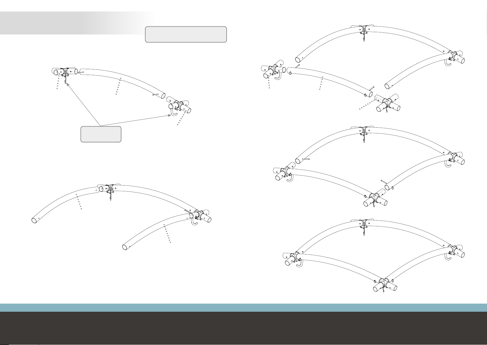
Assemble frame body
STEP 1
Secure all parts with locking pins
(long version) and securing rings
Upper main prole
CS-0389
X-connector
CS-0050
X-connector
CS-0050
Hooks have to
point inwards
Upper main prole
CS-0389
Upper main prole
CS-0389
!
!
Upper main prole
CS-0389
X-connector
CS-0050
X-connector
CS-0050

7 | 246 | 24
Crossover M
Building instructions
www.creative-products.nl
Crossover M
Building instructions
www.creative-products.nl
Locking strip
CS-0337
4x
Securing ring
CS-0248
4x
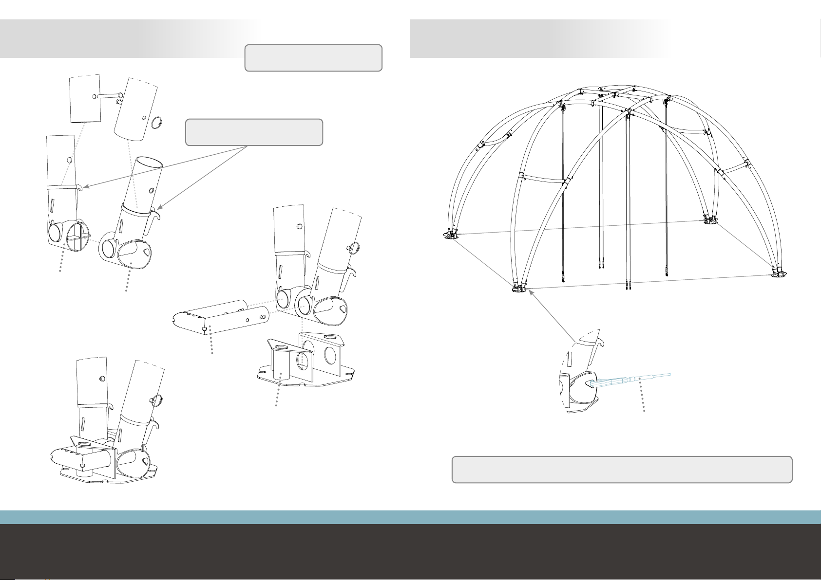
Mount sub frame at frame body
STEP 3
!
!
Pre-assemble the sub frame
STEP 2
Sub frame center
CS-0334
Secure all parts with locking pins
(short version) and securing rings
Joint has to point
downwards
Sub frame beam
CS-0356
4x
Sub frame connector
CS-0336
4x

9 | 248 | 24
Crossover M
Building instructions
www.creative-products.nl
Crossover M
Building instructions
www.creative-products.nl
While building, the structure has to be lifted multiple times so that the assembly can easily be done on oor
level. The structure is designed for two lifting methods:
1. Lifting from below (for example with a traverse lift) by using the subframe. Requirements lifting device:
• minimum lifting height: 4,2 meter
• minimum save working load: 225kg
2. Lifting from above (for example with a crane) by using lifting slings (2 meter, 1000 KG) and the hooks of the
X-connectors
LIFTING
Note: this lifting methode
requires more height for building
!
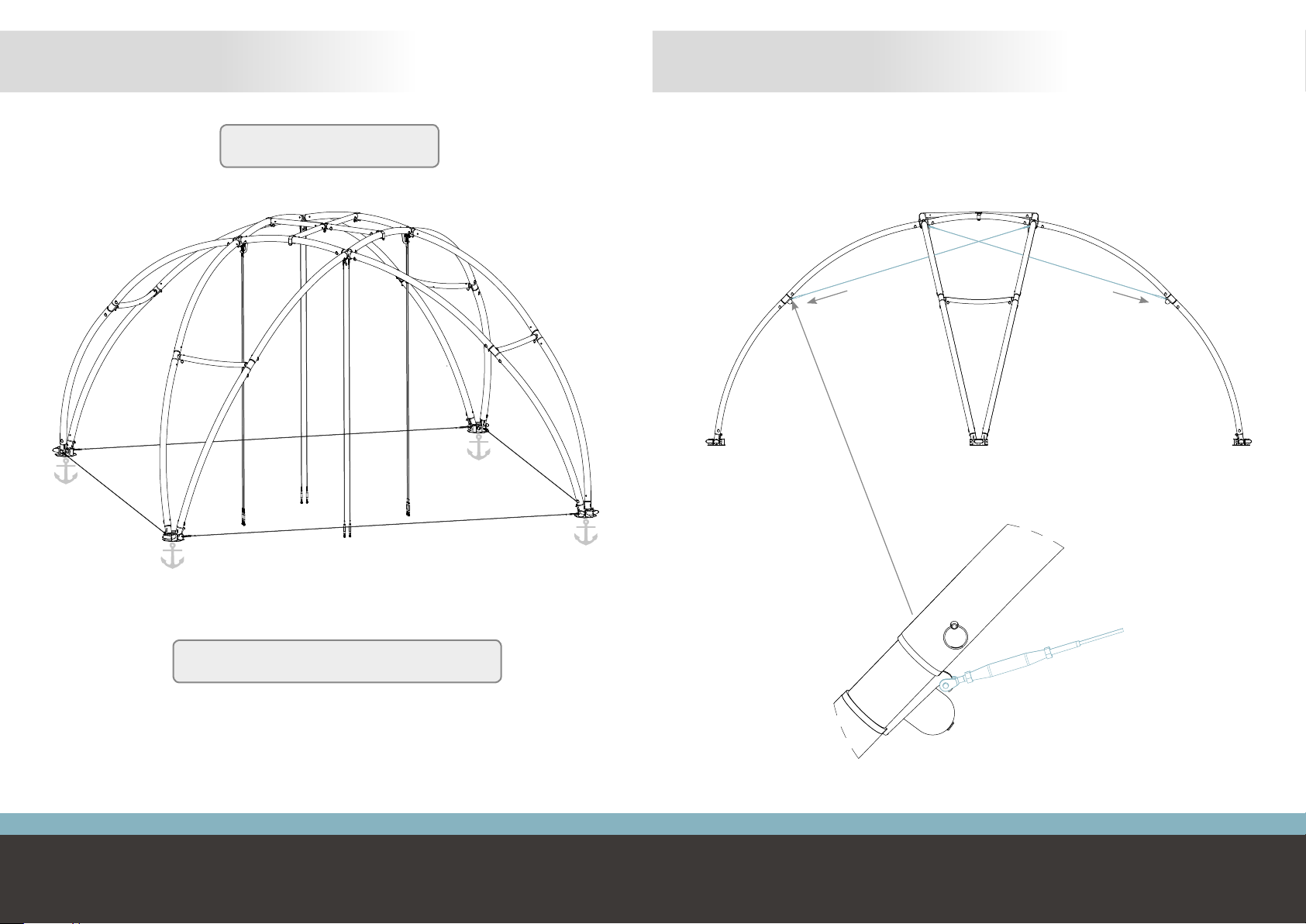
Tension cable
2x per X-connector
CS-0245
Use the 2 inner eyes
of the X-connectors
!
Mount the rst end of the 8 tension cables
STEP 4

11 | 2410 | 24
Crossover M
Building instructions
www.creative-products.nl
Crossover M
Building instructions
www.creative-products.nl
Main prole
CS-0114
8x
Mount the rst level of main proles
STEP 5
Secure all parts with locking pins
(long version) and securing rings
! Pre-assemble the sub proles (4x)
STEP 6
Sub prole
CS-0113
T-Connector Right
Marked with “R”
CS-0117
T- Connector Left
Marked with “L”
CS-0116
L
R
Curvature has to point
downwards/backwards
!
Locking pin
Short version
CS-0105
2x
Securing ring
CS-0248
2x

13 | 2412 | 24
Crossover M
Building instructions
www.creative-products.nl
Crossover M
Building instructions
www.creative-products.nl
L
R
Main prole
CS-0114
8x
Mount the sub proles (4x) Mount the second level of main proles
STEP 7 STEP 8
Secure all parts with locking pins
(long version) and securing rings
! Secure all parts with locking pins
(long version) and securing rings
!
Curvature sub proles
has to point inwards
!
15 | 2414 | 24
Crossover M
Building instructions
www.creative-products.nl
Crossover M
Building instructions
www.creative-products.nl
Foot connector Left
CS-0058
Foot connector Right
CS-0108
Anchor slide
CS-0099
Anchor support
CS-0148 Positioning cable
CS-0246
4x
The positioning cables are used to secure an acurate distance between the feet.
After mounting the positioning cables the structure can be placed on its feet
Pull the legs of the structure outwards to put the positioning cables under tension
!
Mount the feet (4x) Mount the positioning cables
STEP 9 STEP 10
Secure all parts with locking pins
(long version) and securing rings
!
Hooks have to point to the
inside of the structure
!
17 | 2416 | 24
Crossover M
Building instructions
www.creative-products.nl
Crossover M
Building instructions
www.creative-products.nl
Anchor the structure Mount the second end of the 8 tension cables and tension them
By tensioning the tension cables the structure gets its rigidity
STEP 11 STEP 12
For the dierent anchoring options and
instructions see the anchoring guide
!
After anchoring, the positioning cables can be removed.
In stormy conditions the positioning cables have to be
mounted to provide extra stability to the structure
!
19 | 2418 | 24
Crossover M
Building instructions
www.creative-products.nl
Crossover M
Building instructions
www.creative-products.nl
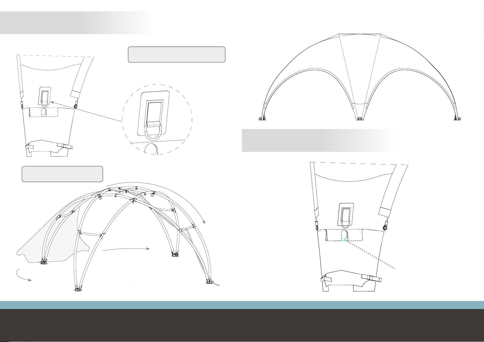
STEP 13
Guide the cover on both sides
!
Place the cover over the structure
The included rope can be used to pull the cover over the structure.
Tie the rope to the lifting eye.
Do not place the cover in windy
conditions or take decent security measures
!
Place the pull bars in the loops of the cover corners
STEP 14
Pull bar
CS-0489
This manual suits for next models
1
Table of contents
Other Creative Accessories manuals


