manuals.online logo
Brands
  1. Home
  2. •
  3. Brands
  4. •
  5. Cree
  6. •
  7. Light Fixture
  8. •
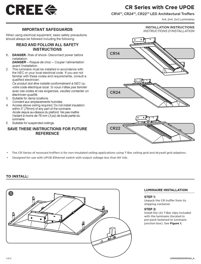
  9. Cree Essentia User manual

Cree Essentia User manual

KI081X02R0
InstallatIon InstRuctIons
Page 1 of 2
EssEntia®
LED SurfacE WaLL Mount cyLinDEr
Includes: ESA-C10-SW
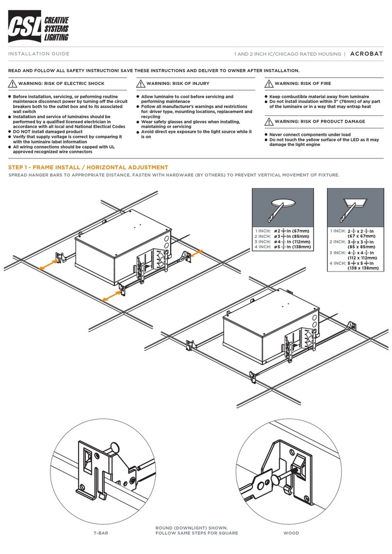
1. 1. Remove the (4) screws securing the canopy to the
mounting plate and slide the canopy over the arm to access
the mounting holes. See Figure 1.
2. Align the mounting plate over the installed junction box and
route the supply wires through the access hole located in the
center of the mounting plate.
3. Using (4) customer supplied mechanical fasteners suitable
for the intended mounting surface; secure the mounting plate
over the installed junction box.
4. Replace the canopy over the mounting plate and secure with
the (4) screws removed in step 1.
5. On the bottom surface or the Mounting Arm, remove the (4)
screws securing the cover to access the Electrical Connections
compartment. See Figure 2.
6. See “Electrical Connections” for wiring instruction.
7. After electrical connections are complete, replace the cover
removed in step 4 ensuring that no wires are pinched.
1. Using the supplied wiring harness, connect the supply wire to
the supply harness wires using the provided wire connectors.
NOTE: The ground wires that are attached to the Electrical
Connections Compartment Cover and to the inside of the
mounting arm need to be connected to the Supply Ground
wire using the provided wire connector.
2. If luminaire has 0-10V Dimming Option, connect the Violet Dim
(+) and Gray Dim (-) leads.
3. Connect the fixture and supply harnesses. See Figure 3.
IMPORTANT SAFEGUARDS
When using electrical equipment, basic safety precautions should always be followed including the following:
READ AND FOLLOW ALL SAFETY INSTRUCTIONS
1. To avoid the possibility of electrical shock, turn off power supply before installation or servicing.
2. When closing cover of fixture, ensure all wires are inside the housing to avoid damage to wires.
3. This product must be installed in accordance with the applicable installation code by a person familiar with the construction and
operation of the product and the hazards involved.
4. IMPORTANT: Damage to luminaire will result when improper voltage is applied. Verify luminaire is suitable for supply voltage by
checking electrical label on luminaire.
SAVE THESE INSTRUCTIONS FOR FUTURE REFERENCE
Figure 1
STANDARD ELECTRICAL CONNECTIONS -
PHASE TO NEUTRAL 120-277V
WALL MOUNT Figure 2
Figure 3



Page 2 of 2
The information in this document in subject to change without notice.
Visit website for patents that cover these products: Patent http://www.cree.com/patents
Visit website for warranties that cover Cree® BetaLED® Technology products:
Warranties http://www.cree.com/lighting/products/warranty
1. Using the supplied wiring harness, connect the supply wire to
the supply harness wires using the provided wire connectors.
NOTE: The ground wires that are attached to the Electrical
Connections Compartment Cover and to the inside of the
mounting arm need to be connected to the Supply Ground
wire using the provided wire connector.
2. If luminaire has 0-10V Dimming Option, connect the Violet Dim
(+) and Gray Dim (-) leads.
3. Connect the fixture and supply harnesses. See Figure 4.
1. Using the supplied wiring harness, connect the supply wire to
the supply harness wires using the provided wire connectors.
NOTE: The ground wires that are attached to the Electrical
Connections Compartment Cover and to the inside of the
mounting arm need to be connected to the Supply Ground
wire using the provided wire connector.
2. Connect the fixture and supply harnesses. See Figure 5.
1. Using the supplied wiring harness, connect the supply wire to
the supply harness wires using the provided wire connectors.
NOTE: The ground wires that are attached to the Electrical
Connections Compartment Cover and to the inside of the
mounting arm need to be connected to the Supply Ground
wire using the provided wire connector.
2. See Figure 6.
3. Connect the supply side connector to the fixture wiring
connector.
STANDARD ELECTRICAL CONNECTIONS -
PHASE TO PHASE 208, 240V
LUTRON ELECTRICAL CONNECTIONS –
ECOSYSTEM DIGITAL DIMMING
Figure 4
Figure 5
UTRON ELECTRICAL CONNECTIONS –
3-WIRE DIMMING
Figure 6




Other Cree Light Fixture manuals

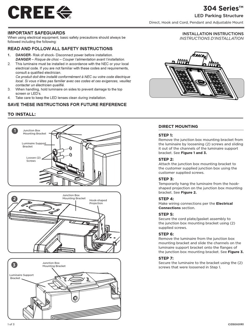
Cree 304 Series User manual

Cree

Cree 304 Series User manual

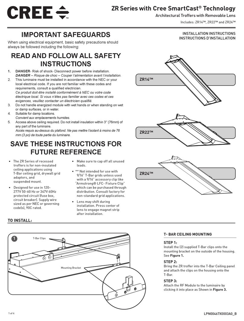
Cree ZR14 User manual

Cree

Cree ZR14 User manual

Cree 304 Series User manual

Cree

Cree 304 Series User manual

Cree CR14 User manual

Cree

Cree CR14 User manual

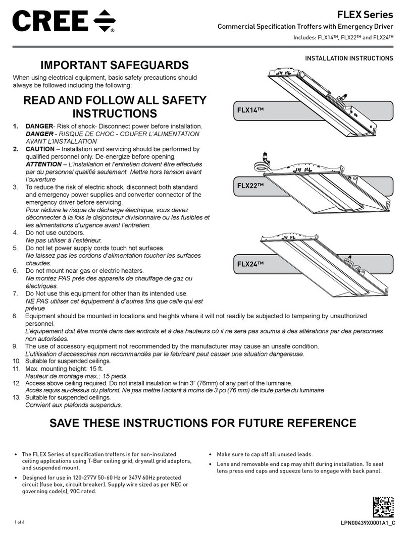
Cree FLEX Series User manual

Cree

Cree FLEX Series User manual

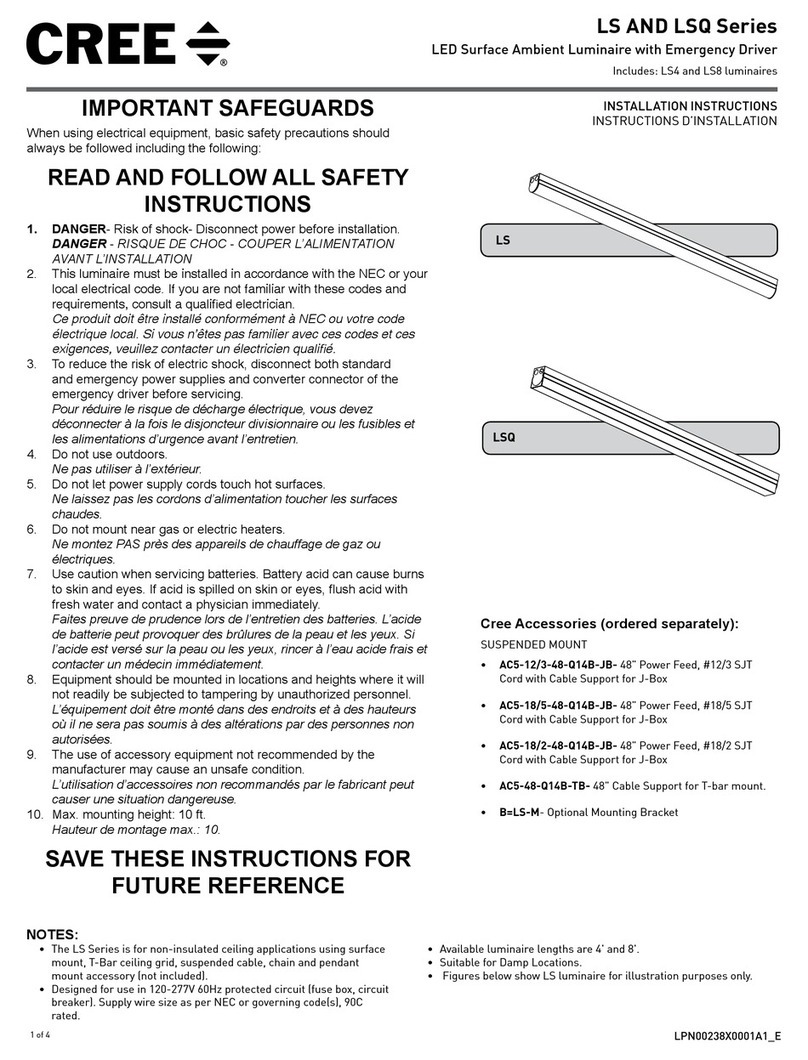
Cree LS Series User manual

Cree

Cree LS Series User manual

Cree XSP Series User manual

Cree

Cree XSP Series User manual

Popular Light Fixture manuals by other brands

Saxby Lighting Recon quick start guide

Saxby Lighting

Saxby Lighting Recon quick start guide

SATTLER LUCE VERDE SLIM Assembly instruction

SATTLER

SATTLER LUCE VERDE SLIM Assembly instruction

POLUX FUNNY DEL78-Y-RGB operating manual

POLUX

POLUX FUNNY DEL78-Y-RGB operating manual

Cameo ROOT PAR 4 user manual

Cameo

Cameo ROOT PAR 4 user manual

Martin MAC 301 user manual

Martin

Martin MAC 301 user manual

Evolights iQ-150S user manual

Evolights

Evolights iQ-150S user manual

Chauvet LED-PANEL4 user manual

Chauvet

Chauvet LED-PANEL4 user manual

AlienPro MINI WASH quick start guide

AlienPro

AlienPro MINI WASH quick start guide

Philips 6910104PH Instruction leaflet

Philips

Philips 6910104PH Instruction leaflet

venalsol AGRO-O instructions

venalsol

venalsol AGRO-O instructions

Cooper Lighting Metalux SA SERIES Specifications

Cooper Lighting

Cooper Lighting Metalux SA SERIES Specifications

Triarch 29320/2 Assembly instruction

Triarch

Triarch 29320/2 Assembly instruction

PacLights FHZL Series installation guide

PacLights

PacLights FHZL Series installation guide

Winter Wonder Lane XL3211074 Operation and safety instructions

Winter Wonder Lane

Winter Wonder Lane XL3211074 Operation and safety instructions

Modulex MMT-101/TLF/01 installation guide

Modulex

Modulex MMT-101/TLF/01 installation guide

Larson Electronics Golight instruction manual

Larson Electronics

Larson Electronics Golight instruction manual

Lightolier Calculite ProSpec PA3H3039 specification

Lightolier

Lightolier Calculite ProSpec PA3H3039 specification

Chauvet Professional ROGUEOUTCAST2BEAM Quick reference guide

Chauvet Professional

Chauvet Professional ROGUEOUTCAST2BEAM Quick reference guide

manuals.online logo
manuals.online logoBrands
  • About & Mission
  • Contact us
  • Privacy Policy
  • Terms and Conditions

Copyright 2025 Manuals.Online. All Rights Reserved.