Cree ZR14 User manual

ZR Series with Cree SmartCast®Technology
Architectural Troffers with Removable Lens
Includes: ZR14™, ZR22™ and ZR24™
1 of 4 LPN00467X0003A0_B
INSTALLATION INSTRUCTIONS
INSTRUCTIONS D’INSTALLATION
TO INSTALL:
T- BAR CEILING MOUNTING
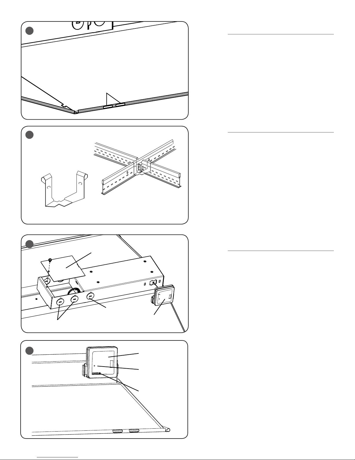
STEP 1:
Install the (2) supplied T-Bar clips onto the
mounting bracket on the outside of the housing.
See Figure 1.
STEP 2:
Bring the ZR troffer into the T-Bar Ceiling panel
and attach the clips on the housing onto the
T-Bar.
STEP 3:
Attach the RF Module to the luminaire by
clicking it into place as Shown in Figure 3.
1
Mounting Bracket
T-Bar Clips
ZR14™
ZR22™
ZR24™
IMPORTANT SAFEGUARDS
When using electrical equipment, basic safety precautions should
always be followed including the following:
READ AND FOLLOW ALL SAFETY
INSTRUCTIONS
1. DANGER- Risk of shock- Disconnect power before installation.
DANGER – Risque de choc – Couper l’alimentation avant l’installation.
2. This luminaire must be installed in accordance with the NEC or your
local electrical code. If you are not familiar with these codes and
requirements, consult a qualied electrician.
Ce produit doit être installé conformément à NEC ou votre code
électrique local. Si vous n’êtes pas familier avec ces codes et ces
exigences, veuillez contacter un électricien qualié.
3. Do not handle energized module with wet hands or when standing on wet
or damp surfaces, or in water.
4. Suitable for damp locations.
Convient aux emplacements humides.
5. Access above ceiling required. Do not install insulation within 3" (76mm) of
any part of the luminaire.
Accès requis au-dessus du plafond. Ne pas mettre l’isolant à moins de 76
mm (3 po) de toute partie du luminaire.
SAVE THESE INSTRUCTIONS FOR
FUTURE REFERENCE
• The ZR Series of recessed
troffers is for non-insulated
ceiling applications using
T-Bar ceiling grid, drywall grid
adaptors, and
suspended mount.
• Designed for use in 120-
277V 50-60 Hz or 347V 60Hz
protected circuit (fuse box,
circuit breaker). Supply wire
sized as per NEC or governing
code(s), 90C rated.
• Make sure to cap off all unused
leads.
• ** Not intended for use with
9/16” T-Bar grids unless used
with a 9/16” accessory clip like
“Armstrong® LFC- Fixture Clip”
which can be purchased through
distribution. Consult factory for
non-standard grid applications.
• Lens may shift during
installation. Press center of
lens to engage magnet strip
after installation.
2 of 4 LPN00467X0003A0_B
Knock-outs
4
DO NOT use third
Knock-out
RF Module
SUSPENDED MOUNTING
STEP 1:
Attach customer supplied cables to the (2)cable
slots on each corner of the housing. See Figure 2
and 3.
STEP 2:
Attach customer supplied cables to mounting
surface using customer supplied hardware.
Ensuring that mounting surface can support the
luminaire.
STEP 3:
Attach the RF Module to the luminaire by clicking it
into place as Shown in Figure 4.
RESET RF MODULE
NOTE: The Blue LED is located behind the CREE
logo on the RF Module. The CREE logo with
illuminate blue when the Blue LED is active.
STEP 1:
Actuate RESET button through the access hole.
Push and hold until LED on RF module begins
blinking rapidly (approximately 6-7 seconds). See
Figure 5.
STEP 2:
Release for 1 sec.
STEP 3:
Press/Hold RESET button for 0.5 sec. Light will turn
off for a few seconds then go to full bright and the
Blue LED on the RF Module should begin a 2 blink
sequence. Figure 5.
TROUBLESHOOTING:
Out of the box, if the light does not turn on when
power is applied:
• Check Wiring with power off
• If wired correctly, check to see if Blue LED
blinking on the RF Module.
• If Blue LED is blinking, then perform a
RESET
(See RESET RF MODULE section).
• If Blue LED is on solid or off, call Cree
Customer Service.
• If you have done a RESET, and the light is
still off, call Cree Customer Service.
If light is unresponsive, use Cree Configuration Tool
to verify configuration.
5RF Module
Access Hole, Reset Button
Inside
Blue LED
Placement
2
Cable Slots
Junction Box
Cover
3
Armstrong® LFC- Fixture Clip to
use for 9/16th applications.

3 of 4 LPN00467X0003A0_B
CLEANING LENS
STEP 1:
Locate the end cap with the arrow marks on it, indicating that
the end cap is removable.
STEP 2:
Grab the lens section next to the end cap and pull lens and
end cap together downward gently. See Figure 6.
STEP 3:
Disengage the other end of the lens from the other end cap.
Once lens is removed perform cleaning. See Figure 7.
STEP 4:
After cleaning is complete insert lens back into fixed end
cap. Push the removable end cap upward into the housing
and using a gentle rocking motion engage the end cap to
retention clip. Check lens for any visible gap between the lens
and luminaire. If necessary push lens upward at gap location
to seal magnetic foam to luminaire. See Figure 8.
FCC NOTICE
To comply with the FCC RF exposure compliance
requirements, this device and its antenna must not be co-
located or operating to conjunction with any other antenna or
transmitter.
This equipment should be installed and operated with
minimum distance 5cm between the radiator & your body.
FCC COMPLIANCE STATEMENT
CAUTION: Changes or modifications not expressly approved
could void your authority to use this equipment.
This device complies with Part 15 of the FCC Rules. Operation
to the following two conditions: (1) This device may not cause
harmful interference, and (2) this device must accept any
interference received, including interference that may cause
undesired operation
This device has been tested and found to comply with the
limits for a Class A digital device, pursuant to Part 15
of the FCC Rules. These limits are designed to provide
reasonable protection against harmful interference when
the device is operated in a commercial environment. This
device generates, uses, and can radiate radio frequency
energy and, if not installed and used in accordance with the
instruction manual, may cause harmful interference to radio
communications. Operation of this device in a residential
area is likely to cause harmful interference in which case the
user will be required to correct the interference at his own
expense.
The LED in the front of this device operates within Risk Group
1 levels per IEC 62471.
INDUSTRY CANADA STATEMENT
This device complies with Industry Canada licence-exempt
RSS standard(s). Operation is subject to the following two
conditions: (1) this device may not cause interference, and
(2) this device must accept any interference, including
interference that may cause undesired operation of the
device. In addition, this device complies with ICES-003 of the
Industry Canada (IC) Regulations.
Le présent appareil est conforme aux CNR d’Industrie
Canada applicables aux appareils radio exempts de licence.
L’exploitation est autorisée aux deux conditions suivantes
: (1) l’appareil ne doit pas produire de brouillage, et (2)
l’utilisateur de l’appareil doit accepter tout brouillage
radioélectrique subi, même si le brouillage est susceptible
d’en compromettre le fonctionnement.
6
7
End Cap
Arrow Marks
Arrow Marked
End Cap
8
Fixed End Cap
4 of 4 LPN00467X0003A0_B
www.lighting.cree.com
© 2017 Cree, Inc. All rights reserved. For informational purposes only. Content is subject to change.
See http://lighting.cree.com/warranty for warranty and specifications. Cree®and SmartCast®are registered trademarks, and
the Cree logo, and ZR14™, ZR22™ and ZR24™ are trademarks of Cree, Inc. Armstrong® is a registered trademark of AWI
Licensing LLC.
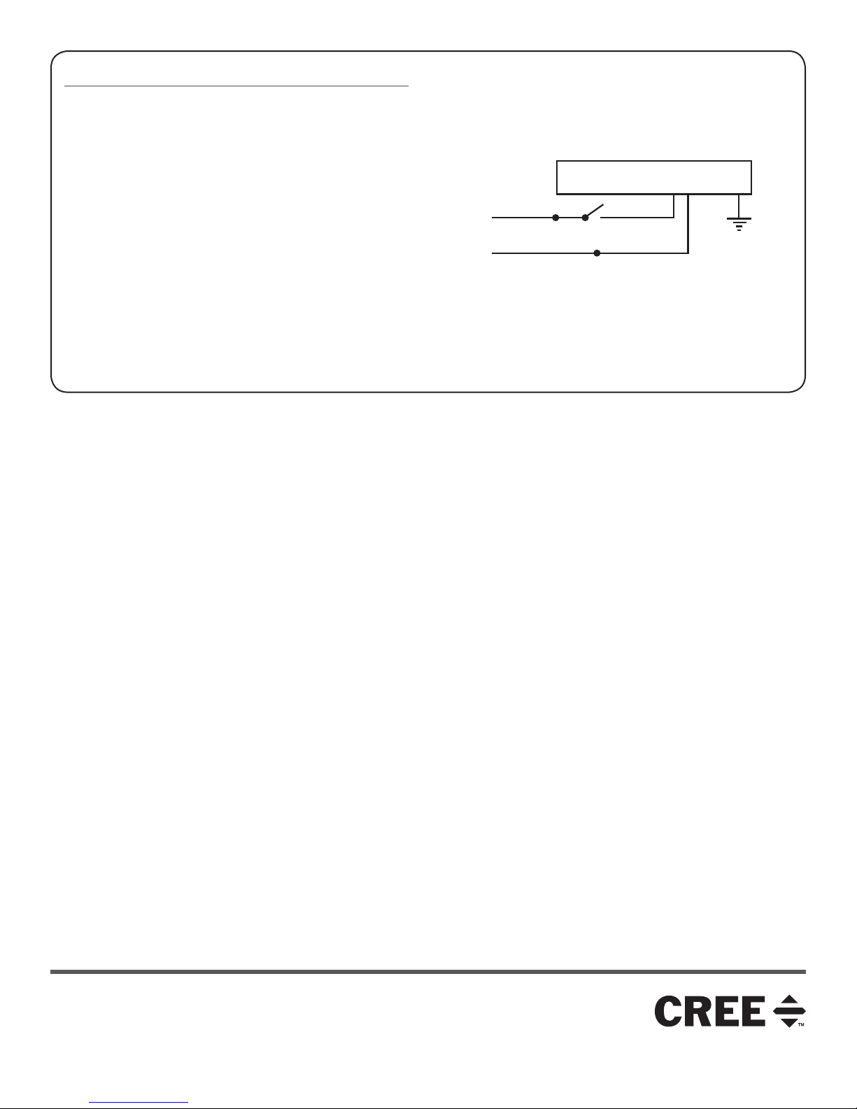
ELECTRICAL CONNECTIONS
STEP 1:
Remove the cover of the junction box and bring in appropriate
power supply to the junction box using one of the knock-outs. See
Figure 3.
STEP 2:
Using customer supplied 90°C minimum rated wire
connectors, make the following electrical connections:
a. Connect the black fixture lead to the voltage supply Line
position, Hot.
b. Connect the white fixture lead to the neutral supply
position.
c. Connect the green or green/yellow ground lead to the
supply ground lead.
STEP 3:
Push all leads into the junction box. Reattach junction box cover
that was removed in Step 1 , make sure no wires are pinched.
LINE
DRIVER ASSEMBLY
BLACK
WHITE
NEUTRAL
This manual suits for next models
2
Other Cree Light Fixture manuals


Popular Light Fixture manuals by other brands

Lightolier
Lightolier JS Series specification

Cooper Lighting
Cooper Lighting Halo L50516 specification

Viessmann
Viessmann 60901 Operation manual

EuroLite
EuroLite BLACK GUN UV-spot user manual

Robe
Robe ColorWash 575 AT ZOOM Service manual

RSA Lighting
RSA Lighting Combolight LV Series LV3803IS Specifications


