Crescent RM-9600 User manual

AUTO REFRACTOMETER
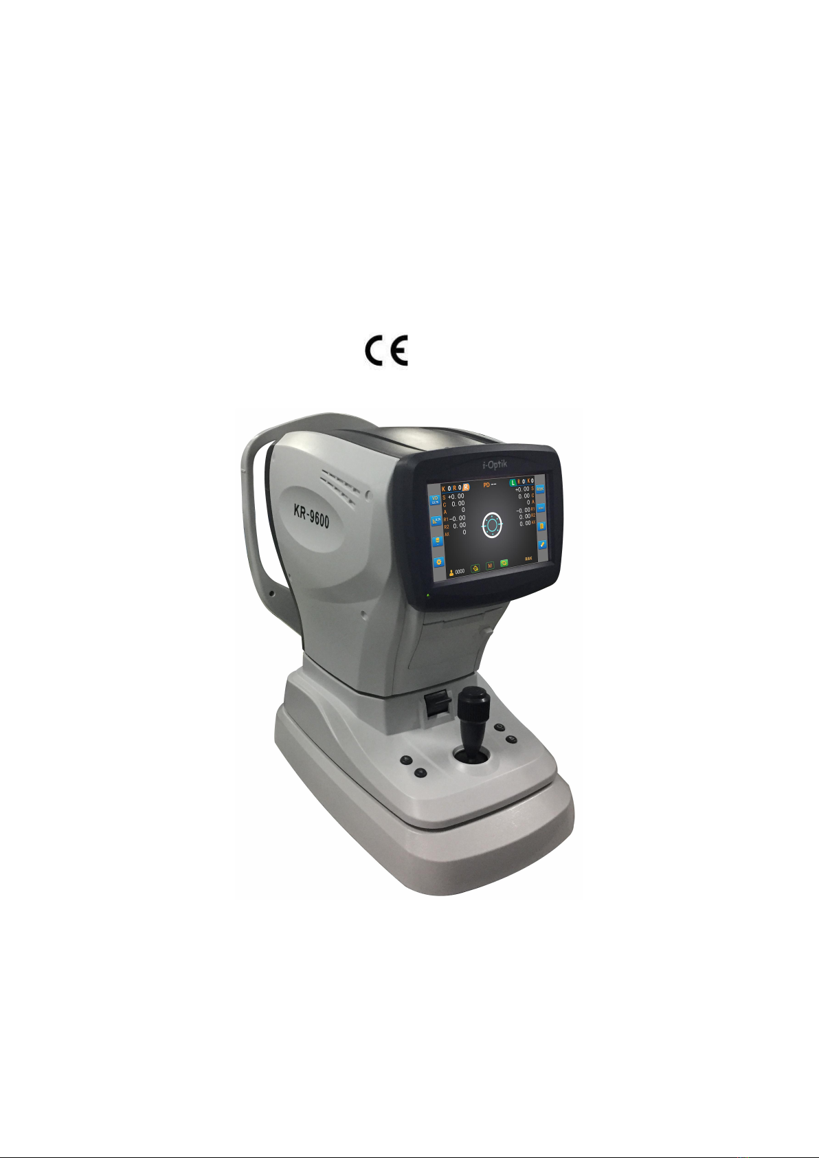
RM/KR-9600 RM/KR-9800
OPERATOR’S MANUAL
1282

1. Introduction.....................................................................................................................................3
1.1 Product Features and Use Scope.......................................................................................... 3
1.2 Classification..........................................................................................................................3
1.3 Main performance index.......................................................................................................4
2. Safety precautions...........................................................................................................................5
2.1 Safety identification.............................................................................................................. 5
2.2 Safety precautions before use.............................................................................................. 5
2.3 Safety precautions during use.............................................................................................. 7
2.4 Safety precautions after use................................................................................................. 7
2.5 Maintenance and check........................................................................................................8
2.6 Disposal................................................................................................................................. 8
3. Configuration and Functions...........................................................................................................9
3.1 Device configuration............................................................................................................. 9
3.2 Accessories..........................................................................................................................10
3.3 Symbols............................................................................................................................... 11
3.4 Operation flow.................................................................................................................... 12
3.5 Set screen description.........................................................................................................14
4. Installation and measurement preparation..................................................................................20
5. Measurement................................................................................................................................21
5.1 Model eye measurement....................................................................................................21
5.2 Patient measurement......................................................................................................... 22
6. Self-diagnosis and maintenance................................................................................................... 23
6.1 Troubleshooting.................................................................................................................. 23
6.2 Printer Paper Replacement.................................................................................................23
6.3 Cleaning and disinfection....................................................................................................23
6.4 Replace fuse........................................................................................................................ 24
6.5 Instrument site change....................................................................................................... 24
6.6 Preventive inspection and maintenance............................................................................ 24
6.7 Scrap....................................................................................................................................25
7. Outline dimension and other instructions....................................................................................25

7.1 Outline specification, Contraindication.............................................................................. 25
7.2 Service life........................................................................................................................... 25
7.3 Disclaimer............................................................................................................................25
8. After-sale service...........................................................................................................................26
9. Main specifications....................................................................................................................... 26
10. EMC(Electromagnetic Compatibility).......................................................................................27

3
1. Introduction
The Auto-Refractometer (RM-9600, RM-9800)/ Auto ref-keratometer (KR-9600, KR-9800) is
used to measure spherical, cylinder, axial, PD, corneal radius and corneal diopter (KR-9600,
KR-9800) of the patient’s eye.
1.1 Product Features and Use Scope
a) The classification of equipment according to the type of shock proof: class I, external
power supply equipment.
b) The classification of equipment according to the degree of shock proof: B type.
c) The classification of equipment according to the ability to prevent liquid entry:
ordinary equipment.
d) Application part of the equipment: chinrest, forehead rest.
e) The type of device power: single phase, network power supply: 100-240V ~ 50/60Hz
50VA.
f) Equipment belongs to non AP or APG type.
g) The operation mode: continuous operation.
h) Equipment belongs to impermanent installation equipment.
1.2 Classification
The model number is RM-9600/ KR-9600/ RM-9800/KR-9800.
The Auto Ref/keratometer is composed of the host, the base and the bracket (according to
the appearance). The bracket material is ABS.
The Auto Ref/keratometer is composed of optical system, electronic system and software,
mechanical system, shells (according to the functional system).
The main difference between the main models KR-9000 is the difference in shape. The
principle and intended uses are the same.
The classification of appearance according to design serial number: KR/RM-9600 is same.
KR/RM-9800 is same.
The classification of functional according to model number: KR-9600/9800 is same.
RM--9600/9800 is same. (The Auto Ref/keratometer KR-9600 and KR-9800 can measure corneal
curvature)
Transport and transport conditions:
Temperature:-40℃- +55℃
Humidity: ≤80%
Atmospheric pressure: 700hPa - 1060hPa (transport), 500hPa - 1060hPa (transport)
Working environment condition:
Temperature:10℃- 40℃
Humidity: ≤80%

4
Atmospheric pressure: 760hPa - 1060hPa
Power requirements:
Voltage: 100-240V~、50/60Hz
Input power: 50VA
1.3 Main performance index
1 Measurable range
Spherical power: -25.00 m-1 - +22.00 m -1。
Cylindrical power: -10.00 m -1 - +10.00 m -1。
Cylindrical axis: 0º - 180º
PD measurement: 10mm - 85mm
Corneal radius: 5mm - 10mm (KR series)
Corneal diopter: 67.50 m -1 - 33.75 m -1 (KR series)
2 Measurement increments(step)
Spherical power (step): 0.12 m -1/0.25 m -1
Cylindrical power (step): 0.12 m -1/0.25 m -1
Cylindrical axis (step): 1º
PD measurement (step): 1mm
Corneal radius (step): 0.01mm (KR series)
Corneal diopter (step): 0.12 m -1/0.25 m -1 (KR series)
3 Tolerance
The tolerance of the Auto refractometer/ Auto ref-keratometer should meet the requirements of
Table 1
Table 1 Tolerance
Measurable range
Tolerance
Spherical power
-10 - +10 m-1
±0.25 m -1
<-10or>+10 m -1
±0.50 m -1
Cylindrical power
-10 - +10 m-1
±0.25 m -1
Corneal refractive radius
≤8.0mm
±0.02mm
>8.0mm
±0.03mm
Corneal refractive power
≤43 m -1
±0.13 m -1
>43 m-1
±0.25 m -1
The tolerance of cylindrical axis: ≤±5º
The tolerance of PD: ≤±1mm
4 General technical requirements
a) The installation of the whole equipment should be firm and isn’t obvious loosening.
Chinrest should be able to smooth lifting. The rated load of chinrest is 2.5Kg. Shaking the joystick,
the device should be flexible to move all around.
b) The surfaces of all optical components shall be clean, free of damage, and no other
defects that affect light transmission or imaging.

5
c) Display screen should be able to clear imaging.
d) Digital display complete, stable, no flicker and print legible. Measurement results should
include left and right eye identification, spherical power and cylindrical power, +/-, axis and
degree, etc.
e) Auto ref/keratometer has the function of printing test results.
f) Optical radiation shall comply with the applicable requirements of ISO15004-2.
5 Under the working conditions, the noise should not be greater than 55dB (A).
6 The surface temperature of the device is not more than 15℃.
7 Safety requirements shall comply with the requirements of GB9706.1.
8 The test environment shall be consistent with the requirements of the mechanical test
environment II group in GB/T14710-1993.
9 The Device for external connection with Auto ref/keratometer shall comply with the
requirements of GB9706.1.
2. Safety precautions
2.1 Safety identification
In this manual, signal words are used to designate the degree or level of safety alerting.
The definitions are as follows.
CAUTION
CAUTION: Indicates a potentially hazardous situation which, if not
avoided, may result in minor or moderate injury or property damage
accident.
Even situations indicated by CAUTION may result in serious injury under certain conditions.
Safety precautions must be strictly followed at all times.
2.2 Safety precautions before use
CAUTION
The safety precautions and operating procedures must be thoroughly understood prior to
operation of the device. Use of the device outside the scope of this manual may cause
adverse events.
Do not open shell and do not touch the interior of the device. This may cause electric shock
or instrument failure.
Install and use the device in an environment that meets the following conditions.
Temperature:10℃- 40℃
Humidity:≤80%
Atmospheric pressure:760hPa - 1060hPa
A room with low dust and little light
A location free from vibration and shock
--- If the device is not installed and used under the above conditions, the reliability of

6
measured results is impaired, and malfunction may result. In addition, there is a
possibility of injury if the device receives shock and falls down.
Avoid storage the device near water, poisonous gas or liquid. The device may be corrosion or
failure.
Avoid installing the device where it is exposed to direct air-conditioning flow. Changes in
temperature may result in condensation inside the device or adversely affect
measurements.
Be sure to use a power outlet which meets the power specification requirements. If the
voltage is too high or too low, the device will not perform properly, and fire may occur.
To avoid the risk of electric shock, the equipment must be connected with the power supply
in the case of the protection of grounding equipment. Electric shock or fire may occur if the
device malfunction or electric leakage.
Do not use socket overload. This May cause fire.
Insert the power plug into the socket. Improper connections may cause a fire.
Never use a power strip or extension cable to supply the device with power. This may cause
failures and fire.
Do not place heavy objects on the power cord. A damaged power cord may cause fire or
electric shock.
Switch off the power switch and disconnect the power cord from the power outlet before
connecting the cable. Otherwise it may result in device failure
When moving the instrument, be sure to turn off the power switch, unplug the power cord
and the power cable, lock the head (with a lock sign),to avoid equipment falling that may
cause injury or equipment damage.
Special packing materials are used to protect the equipment during transportation.
Excessive vibration or shock can cause malfunction.
When installing and operating equipment, observe the following EMC instructions (EMC):
1. The device can’t be used in conjunction with other electronic devices to avoid
electromagnetic interference with other electronic devices.
2. The equipment can’t be used in the same room with other devices, including life support
devices, other devices that have a significant impact on the lives of patients and the results
of treatment and the measurement or treatment devices of small current.
3. The equipment can’t be used in conjunction with portable and mobile radio frequency
communication devices because of their electromagnetic interference may adversely affect
the operation of the device.
4. Don’t use cables and accessories other than those specified by the company. These may
increase the electromagnetic wave emitted by the equipment or system and reduce the
electromagnetic interference resistance of the device.
If there is a potential electromagnetic interference between the equipment and other
equipments, shielding measures should be taken or the location of the device to be
changed to reduce the possible interference.

7
2.3 Safety precautions during use
CAUTION
When the equipment is disuse, please turn off the power and cover the dust cover. If the
equipment is exposed for a long time, it may have dust, which will affect the accuracy.
Please check the equipment before the operation. If there is any abnormal, do not use the
equipment. The equipment used to abnormal conditions that may affect the accuracy of the
data, the unexpected failures or diagnosis errors may cause harm.
Before measuring each patient, clean the chinrest and forehead rest with clean gauze or
absorbent cotton. If necessary, dampen a cloth with rubbing alcohol and gently wipe them
off. If you use a Chinrest paper, a replacement for each patient.
Keep the measuring window free of fingerprints and dust. Also confirm that it is not dirty
before use, or else measurement accuracy may decrease substantially.
In the event of smoke or strange odors, immediately turn off the device and disconnect the
power plug from the power outlet. After it is certain that the smoke has stopped, contact
MSOC or your authorized distributor.
The continued use of the equipment under unusual circumstances may cause a fire or
electric shock. In case of fire, use a dry powder (ABC) fire extinguisher.
Never press on the LCD with a hard object such as a ball-point pen. Keep magnetic objects
away from the LCD. Malfunction of the device may result.
Do not operate the LCD screen with wet hands. Water infiltration devices may cause
malfunction of the equipment
There may be a few dead or constantly-lit pixels on the LCD. This does not represent failure
of the LCD. It is due to the structure of the LCD.
Only after training qualified personnel can operate the instrument, or operate under its
guidance.
2.4 Safety precautions after use
CAUTION
If the device is a long period of disuse, disconnect the power supply. Dust may collect
moisture that may cause short circuit or fire.
Occasionally use a dry cloth to clean the tip of the power supply plug. If the dust falls on the
tip, water may be collected, resulting in a short circuit or fire.
Don't jerk when pulling out power line. This will destroy the metal line and may cause
electric shock, short circuit or fire.
Maintain the following environmental conditions during transport and storage of the device.
Temperature:-40℃- +55℃
Humidity:≤80%
Atmospheric pressure:700hPa - 1060hPa(transport)、500hPa - 1060hPa(storage)
A location with low dust
A location not exposed to direct sunlight

8
Special packing materials are used to protect the equipment during transportation.
Excessive vibration or shock can cause malfunction.
2.5 Maintenance and check
CAUTION
Do not wipe any part of the instrument with a solvent or a strong cleaning solution.
Otherwise the instrument may be damaged.
Do not use organic solvents such as paint thinner to clean the outside of the device.
Otherwise the surface of the equipment may be damaged.
Avoid touching the optical components of the instrument to prevent performance
degradation caused by fingerprints or grease stains on the lens set.
Any repairs and services to this instrument must be carried out by personnel or dealers
trained by MSOC.
Adjustments must be made by the technical service personnel of MSOC or other authorized
personnel.
The battery of the instrument must be replaced by the technical service personnel of MSOC
or other authorized personnel.
When the equipment is returned to the company for repair or maintenance, use a clean
cloth dipped in the alcohol disinfection device (especially the area of patient contact).
When there is a big difference between the results of the Auto ref/keratometer
measurements and the subjective measurements, please contact MSOC or the dealer to
determine whether the current equipment requires calibration of the measurement
accuracy.
2.6 Disposal
CAUTION
Follow local governing ordinances and recycling plans regarding disposal or recycling of
device components.
It is recommended to deal with industrial waste by the designated contractor.
Deal with packaging material in accordance with local laws and regulations.

9
3. Configuration and Functions
3.1 Device configuration
Figure 1 instrument view
1.7 inch resistive screen: Display measurement results. The screen can adjust angle.
2.Power pilot lamp: When the instrument is working, the indicator light is bright.
3.Printer: print measurement results.
4.Measurement button: When the measurement button is pressed, measurement starts.
5.Joystick: Adjust the measuring window position forward and backward/ Left and right / up and
down.
6.Chinrest up/down button(/):Realize the function of lifting the chinrest.

10
7.Reset print key(/): Reset print function.
8.Measuring unit: It is functional unit.
9.Locking lever: Fixation the main body to the base.
10.Power switch: Turn on or off the instrument power switch.
11.Forehead rest: Here on the forehead.
12.Measuring window: Measurement of retinal imaging
13.Chinrest: Fixed chin.
14.Eye level marker: The height of the chinrest should be adjusted so that the patient’s eye
roughly aligns with this line.
15.Adjust the foundation: Support the instrument to adjust the level of equipment.
16.Fixing pins: Fix the model eye and chinrest paper.
17.Fuse holder: 2 fuses installed inside.
18.Power inlet: Connect ~220V, 50Hz AC.
19.The cover of measuring window
3.2 Accessories
1.Socket head wrench: Unlock plug screw.
2.Model eye: Use to proofreading accuracy.
3.Fuse wire: To prevent short circuit.
4.Printing paper: Measurement of retinal imaging.
5.Operator’s manual: Instructions for use of this device.
6.Dust cover: When not using the instrument, dustproof.
7.Chinrest paper:Customer put on the chinrest.
8.Horizontal bubble: Display instrument level.

11
WARNING
The instrument accessories are provided by MSOC, and the accessories of other
manufacturers need to be verified and confirmed before use.
3.3 Symbols
The following symbols are applied to the device.
0120
Equipment is to meet the basic requirements of the EU
MDD 93/42/EEC.
Indicates that this equipment is to prevent moisture.
Reading operator’s manual.
Indicates that the degree of protection against electric
shock is of a Type B Applied Part.
Indicates the requirements for disposal of electronic
and electrical equipment.
Indicates the equipment manufacturers.
EU authorized representative.
Indicates the year of manufacture.
Warning, please read the operator’s manual before
using.
Indicates the device serial number.
“丨”and “O” respectively represent the power switch
on and off.
Alternating current.
Fuse indication.
3V CR1220 button battery.
Push down to lock the mobile body .Push up to unlock
the mobile body.
Joystick: For the front and back / left and right / upper
and lower to adjust the measurement window
position. The window rises when the joystick is turned

12
clockwise. The window drops when the joystick is
turned counterclockwise. Press the button when the
focus is completed.
Button for chinrest up.
Button for chinrest down.
Button for reset.
Button for print.
3.4 Operation flow
The design block diagram of the software and user interface is shown below. Through the
operating interface, the user can achieve the measurement, data display, image analysis, the
parameters and functions of the modification.
Parameter setting Screen
Start
Data display screen
Start screen
Measurement
screen
Image analysis screen
RM Parameter
KR Parameter
Function setting
Information setting
Time setting
Operation screen flow chart

13
1.Measurement screen
As shown in the figure:
The function buttons on the screen and the display of each region are as follows:
Set button:Press this button to enter the parameter settings interface, specific in the
chapter.
Clear button:Press this button to clear the test record in memory.
Display history data button: Press this button to display the measured historical data.
Display the symbol of the cylinder: touch this button can be cycle
switch.
PD Measurement button: Touch this button to enter the PD Measurement screen.
Measurement mode switch: Touch this key to circularly switch measurement mode.
The show step of the Sphere and cylinder: Touch the key to circularly switch
the step.
VD display: Touch this key to circularly switch VD value.
Count the times of left and right measurement: "L" means "left".
The second letter R represents the measurement of REF. The third is the times of measurement.
The fourth letter K represents the measurement of KER. The last is the times of measurement.

14
Count the times of left and right measurement: The first letter K
represents the measurement of KER. The second is the times of measurement. The third letter R
represents the measurement of REF. The fourth is the times of measurement. The last "R" means
"right".
The value of PD display: When left and right eye measurements are completed and
PD switch turn "ON", the PD value will be displayed. Otherwise displayed “- -”.
For REF data display Three forms of corneal curvature
data display
Serial number of patients
/ Manual / automatic mode: Touch this button to switch measurement
mode between manual and automatic.
/ Manual / auto alignment method: Touch this key to switch up and
down alignment between manual alignment and automatic alignment.
/ IOL switch button: Touch this key to switch IOL mode.
3.5 Set screen description
Touching the setting button in the measurement interface, you can enter the parameter settings
screen.

15
The buttons on the left side of the screen are all kinds of function parameters:
Touch this button to display the REF function parameters.
Touch this button to display the KER function parameters.
Touch this button to display the function setting parameters.
Touch this button to display the information setting parameters.
Touch this button to display the time setting parameters.
Touch this button to return to the measurement screen.
The Description of functional parameters is as follows:
1. REF functional parameter:

16
RM step: 0.12D / 0.25D
VERTEX DIST: 0 / 12 / 13.5 / 15
CYL SIGN: -/ + /MIX
AR CONTINUE:1/3/5
FOGGING: one time/always
2. KER functional parameter:
KM unit: MM / D / AVG
KM Display: 0.12D / 0.25D
REF INDEX: 1.332 / 1.336 / 1.3375
KM CONTINUE 1/3/5
3. Function setting:

17
Language: English / Chinese
PD display: OFF / ON
Screen Sleep: OFF / 5MIN / 15MIN
Beep job: OFF / ON
Auto print: OFF / ON
RM print: OFF / AVG / STD
KR print: OFF / AVG / STD
Eye Print: OFF / ON
RS232C output: OLD / NEW
baud rate: 115200 / 9600 / 4800 / 2400
4. Information setting

18
Set information 1 and information 2. Information 1 and information 2 will be printed on the top
and foot of the prescription list.
5. Time & Date setting
Set the date and time of the instrument.

19
Button in the left of the screen respectively expressed:
Touch this key to show that REF measures the last ten sets of historical data.
Touch this key to show that KER measures the last ten sets of historical data.
Touching this button, according to the function set print REF and KER measurement
data.
Touch this key to clear all the measurement data. The measurement process reset.
Touch this button to return to the measurement screen.
The icons above the title bar:
Serial number of patients
The value of PD display: When left and right eye measurements are completed and
PD switch turn "ON", the PD value will be displayed. Otherwise displayed “- -”.
This manual suits for next models
3
Table of contents