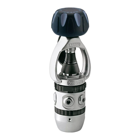
Cressi T10 S.C. Manual

Via Gelasio Adamoli, 501 - 16165 - Genova - Italia
Tel. +39 010 830.79.1 - Fax +39 010 830.79.220
erogatori
regulators
detendeur
atemregler
regulador
пользователя
呼吸调节器
Manuale d’uso
Direction for use
Manuel d’instructions
Bedienungsanleitung
Manual de istrucciones
Pуководство
潜水呼吸调节器使用手册
made in Italy

50
TABLE OF CONTENTS
Introduction .........................page 51
Main Components ..................page 51
1) FIRST STAGES ......................page 53
1.1 T10 – T10 S.C. balanced diaphragm
firststage .............................page 54
1.2 MC9 balanced diaphragm 1st stage
MC9S.C. .............................page 58
1.3 MC5 balanced diaphragm 1st stage . . . . . .page 60
1.4 AC2 in-line piston 1st stage . . . . . . . . . . . . .page 62
1.5 Performance . . . . . . . . . . . . . . . . . . . . . . . . . .page 63
2) SECOND STAGES ...................page 67
2.1 Master 2nd stage . . . . . . . . . . . . . . . . . . . . . .page 68
2.2 Master 2nd stage,
disassembling and maintenance . . . . . . . . .page 71
2.3 Ellipse Balanced 2nd stage . . . . . . . . . . . . .page 72
2.4 Ellipse Balanced second stages
Disassembly and maintenance . . . . . . . . . .page 74
2.5 Ellipse second stages . . . . . . . . . . . . . . . . . . .page 75
2.6 Ellipse, disassembly and maintenance . . . .page 77
2.7 XS Compact Pro/
XS Compact 2nd Stage . . . . . . . . . . . . . . . . .page 78
2.8 XS Compact, disassembly and servicing . .page 81
2.9 XS2 2nd stage . . . . . . . . . . . . . . . . . . . . . . . .page 82
2.10 Performance . . . . . . . . . . . . . . . . . . . . . . . . . .page 86
3) USE AND MAINTENANCE ...........page 89
3.1 Use of the regulator and risk assessment .page 90
3.2 Checks before use . . . . . . . . . . . . . . . . . . . . .page 90
3.3 Mounting the regulator to the tank . . . . . . .page 91
3.4 Use of the regulator in cold water . . . . . . . . page 92
3.5 Care and maintenance
of the equipment . . . . . . . . . . . . . . . . . . . . . .page 92
3.5.1 Caring for the equipment . . . . . . . . . . . . . . . .page 92
3.5.2 Equipment maintenance . . . . . . . . . . . . . . . .page 93
3.6 Use with Nitrox mixtures . . . . . . . . . . . . . . . .page 93
3.7 Maintenance/recording of procedures
(Service Record) . . . . . . . . . . . . . . . . . . . . . .page 95
3.8 Cressi-sub Certified Combinations . . . . . . .page 96
4) TABLES ..............................page
350

51
ENGLISH
Introduction
Congratulations! Continual research and evolution carried out at
our technical centres, together with Cressi-sub’ s usual reliability,
have led to the product you just purchased, which will allow you
to dive comfortably and safely for a long time.
All Cressi-sub regulators are certified for use up to 50 m/55 yd.
and some for use in cold water with temperatures < 10° C/50°F,
having got through the strict test at 4°C/39°F (+0 -2) prescribed
by the UNI EN 250:2014 according to the EC directive 89/686,
which sets the essential safety requisites of Individual Protection
Devices (DPI).
Main Components
Regulators’ main task is reducing the pressure of the compres-
sed air contained in the tank to the same level as the environ-
ment’ s, supplying breathable air when required by the diver.
They are composed of a “first stage”, working as main pressure
reducer and a “second stage” (kept in the diver’ s mouth), which
adjusts the pressure precisely to the same value as the environ-
ment’ s. The regulator is part – together with tank, valves and
sling – of a complete underwater breathing system, known as
“SCUBA” (Self Container Underwater Breathing Apparatus).
This handbook describes all models of Cressi-sub range, all rea-
lized in high quality materials to guarantee pleasant dives and
high performance, together with the easiest ways of use and-
maintenance. The instructions and directions found in this manual
are based on the most up-to-date information about the equip-
ment available before printing.
Cressi Sub reserves the right to make changes at any time.
NOTE: This handbook does not replace a diving training cour-
se! All Cressi-sub devices must be used by divers who have
attended regular courses held by certified trainers.
Using underwater devices without a licence or the necessary
technical training may be dangerous for the diver’ s safety and
life itself.
Besides, in order to guarantee the maximum safety, the devi-
ces must be serviced only by the producer or an authorized-
centre.
You can find your authorized Cressi-Sub center by
asking your dealer, or Cressi Sub S.p.A. itself
(email: [email protected]).
�WARNING: CRESSI-SUB DECLINE ANY RESPON-
SIBILITY FOR ANY SERVICING CARRIED OUT BY
UNAUTHORIZED PERSONNEL.
�WARNING: SCUBA devices complying with EN
250:2014 standard must not be used by more
than a diver at the same time.
�WARNING: in case the components of a SCUBA
are set and used by more than a diver at the same
time, their performance in cold water might not
satisfy the requisites prescribed by EN 250:2014
standard.
�WARNING: In order to carry out a totally safe
dive, Cressi-sub recommend to use a tank sup-
plied with a valve featuring two separate outlet
ports, with which two complete regulatorsare to be
con-nected.

Direction for use regulators
1.1 -T10 – T10 S.C. balanced diaphragm first stage
1.1 -MC9 balanced diaphragm 1st stage - MC9 S.C.
1.2 -MC5 balanced diaphragm 1st stage
1.3 -AC2 in-line piston 1st stage

54 FIRST STAGES
1.1. - T10 – T10 S.C. balanced diaphragm first stage
The T10 balanced diaphragm first stage offers a compact and
light structure protected with a special and innovative PVD (Phys-
ical Vapor Deposition) treatment obtained by depositing physical
vapor used to create an exceptionally resilient protective surface
coating with extraordinary chemical-physical characteristics, as
well as giving a particularly pleasant aesthetic and extremely tech-
nical appearance.
The ergonomics of the T10 balanced diaphragm first stage pres-
ents the functioning mechanism arranged perpendicular to the
air entry axis that thereby forms a “T” profile designed to guaran-
tee perfect arrangement of the HP and LP hoses, avoiding inter-
ference with the equipment connected to the first stage; reduced
size (particularly used in the SC version particularly suited to cold
water), as well as additional inspection capacity and access to the
HP valve mechanism to simplify maintenance and disassembling
of the regulator.
It provides outstanding respiratory performance, constant in any
use condition, thanks to the compensated diaphragm mecha-
nism that enables maximum respiratory comfort to be obtained
during any dive phase, from the surface to maximum depths.
In fact, the regulator provides the same intermediate pressure in-
dependent of the pressure contained in the tanks and maintains
performance at any depth.
Contrary to most regulators currently on the market, offering op-
timum performance when the tank is full at maximum working
pressure, the T10 first stage was designed to offer optimum per-
formance when the tank is close to empty.
This “hyper balancing” feature was possible using a system
that adapts intermediate pressure taking into account the air den-
sity as the depth increases and the progressive increase in pres-
sure drop as the tank empties.
Thanks to this feature, the T10 first stage assists the diver in the
dive, guaranteeing the highest working performance which in-
creases further during the notoriously critical surfacing phase of
surfacing.
The compensated diaphragm mechanism phase, with a "T" air
entry, or rather the HP valve arranged perpendicular to the air
entry axis further guarantees considerable passage of air quan-
tity with a pressure drop, between the inhalation and exhalation
phase, which is reduced considerably.
These characteristics are the result of innovative technical solu-
tions in the design and make the 1st stage among the smallest
and lightest regulators on the market and one of the top per-
forming in its category.
In this first stage (Fig. 1), the flexible diaphragm protects and seals
the mechanism inside the system and transmits pressure varia-
tions in the water to the high pressure valve.
fig. 1

55
ENGLISH
55
The HP poppet valve, which is extremely resilient and easily re-
placed during periodic maintenance, is manufactured in the latest
generation thermoplastic elastomers. This valve boasts the exclu-
sive feature of sliding inside a special lined cylinder, also manufac-
tured in self-lubricating thermoplastic material. The inner surface of
this cylinder, which is completely free of oxidation phenomena,
drastically reduces friction and makes the valve stroke extremely
fluid and precise, guaranteeing optimum respiratory comfort. The
HP poppet valve can also work perfectly guided on a pneumatic
seal compartment, guaranteed to last long thanks to the special
design of the piston sleeve that hinges the valve, without even
making it rotate on its own axis. By doing so, the 1st stage per-
formance can be kept constant and unchanged over time.
The HP valve closure nozzle, manufactured in stainless steel 316, is
interchangeable to facilitate periodic maintenance of the 1st stage.
Air entry in the first stage is protected by a sintered conical filter in
compact, sintered and nickel-plated phosphor bronze micro-
spheres, to enable better air filtering thanks to the broader filter-
ing surface guaranteed by the shape which also guarantees the
passage of an elevated air flow, typical of this regulator and with-
holds any impurities from tank and valve.
The intermediate pressure regulation system of the T10 balanced
diaphragm 1st stage follows the tradition of all Cressi-sub first
stages, allowing convenient and fast regulation of intermediate
pressure without having to disassemble parts of the regulator.
�WARNING: intermediate pressure regulation should only be
carried out by authorised Cressi-sub centres and the calibration
values CANNOT and MUST NOT be changed by the user, to
avoid prejudicing the good working order of the regulator. We
cannot be held in any way liable for any intervention carried out
by staff unauthorised by Cressi-sub.
The Cressi-Sub authorised centres can be indicated by retailers
The balanced diaphragm first stage has a compact and light struc-
ture manufactured in naval brass protected with a PVD (Physical
Vapor Deposition) surface treatment and inner parts in stainless
steel, chromed brass and the latest generation thermoplastic resin.
It avails of 4 low pressure (LP) 3/8” ports, adequately angled for
optimal distribution of the hoses that avoid interference with the
attached equipment, and 2 high pressure (HP) 7/16” ports with a
micrometric perforation for air release, ensuring maximum safety
also in the event of accidental breakage of the high pressure
hose, avoiding the risk of rapid tank emptying.
�WARNING: on the HP ports of the first stage, an underwater
gauge and/or an underwater computer must be connected to
also incorporate the gauge function. Since the tanks are not
equipped with a reserve device, it is absolutely indispensable to
use a gauge that indicates progressive air consumption when
diving and which clearly highlights the reserve pressure has been
reached, which should be considered as unusable air for the
purpose of the dive itself, but only as an emergency air reserve.
Diving without a gauge is dangerous because there is no way of
controlling consumption and you can suddenly find yourself with-
out air during a dive, putting your life in serious danger.
Connection of the first stage to the tank valve can take place
using an international connection, using a new yoke with an ex-
tremely modern design or a threaded coupling DIN 300 bar, both
according to EN ISO 12209 as referenced in the standard EN
250:2014.
As with all regulators in the Cressi-sub range, the T10 first stage
offers the possibility of making certain manufacturing compo-
nents of the regulator compatible, allowing interchanging parts
with other diaphragm first stages in the current range.
Use of the T10 balanced diaphragm first stage is advised, com-
pared to the piston models, for diving in waters full of suspended
FIRST STAGES

56
particles or dissolved mineral salts, or for use in cold water (with
temperatures under 10°C), because all parts of the regulator
mechanism are insulated for contact with water.
For dives in extreme conditions, however, the T10SC version is ad-
vised, equipped as standard with a special Seal Chamber (S.C.).
�WARNING: to deal with diving in cold water (temperature
<10°C or < 50°F) Cressi-sub recommends use of a tank
equipped with a pillar valve with two independent ports outlet,
where two complete regulators can be connected.
�WARNING: adequate technical preparation is necessary to
deal with diving in cold water (temperature <10°C or < 50°F ).
Cressi-sub recommends you carry out this type of diving after
taking a specific course given by qualified instructors. It is im-
portant not to wet the regulator before use and then expose it
to air (which can be well under zero degrees). Do not use the
purge button, particularly with the regulator level with Venturi
effect in the “dive” position. If possible, keep the regulator in
warm surroundings when not in use.
The Seal Chamber is used to make the T10 balanced diaphragm
first stage completely waterproof, avoiding water entry not only
inside, but also in contact with the diaphragm and the calibration
spring on the 1st stage, thereby creating an air chamber upstream
of the regulator and its components, working like a proper thermal
barrier. All problems are therefore avoided relating to contact with
water full of suspended particles, sand, dissolved mineral salts and
with cold water which, especially at temperatures below 10°C
could form the foundation for possible freezing of the regulator.
The Seal Chamber (fig.2) consists of a special metal insert with a
particular “radiator” shape designed to increase thermal ex-
change between the ambient temperature and the temperature
inside the regulator, preventing its possible freezing effect, and a
metal cap containing a silicone membrane inside. This, on warn-
ing of the ambient pressure variations, inverts and thereby trans-
mits oscillations to the ambient pressure transducer beneath
which, coming in contact with the main diaphragm, acts as a
transmission element which transfers all information on the ex-
treme pressure variations to the diaphragm. The main diaphragm
which, in turn, protects and seals the mechanism inside the sys-
tem, then transmits the pressure variations of the water to the
high pressure valve.
�NOTE: before assembling the Seal Chamber S.C. the
balanced diaphragm first stage must be calibrated. To ensure
the regulator works properly, strictly comply with the calibration
values outlined in the regulator performance table. Regulator
calibration is not restricted by the ambient pressure variations
transmission disk.
fig. 2
FIRST STAGES

57
ENGLISH
�WARNING: intermediate pressure adjustment should only
be carried out by authorised Cressi-sub centres and the cali-
bration values CANNOT and MUST NOT be changed by the
user, to avoid prejudicing the good working order of the regu-
lator. We cannot be held in any way liable for any intervention
carried out by staff unauthorised by Cressi-sub.
The Cressi-Sub authorised centres can be indicated by retailers
The T10 first stage therefore can be used in cold water (with a
water temperature under 10 °C), since it complies with Directive
89/686/EEC dated 21/12/1989, checked and certified by the Test
Authority No. 0474 RINA located in Genoa, tested in compliance
with standard EN 250:2014 that establishes the Personal protec-
tive Equipment (PPE) category III, requirements and therefore
outlines the CE marking followed by identification of the certifica-
tion authority (0474) pursuant to Art. 11A of the Directive
89/686/EEC.
The considerable technical solutions, combined with the high
quality of the materials used, ensure that this first stage regulator
is fully reliable and capable of providing the highest performance
extended over time.
Additional important information relating to our equipment can be
found on the website www.cressi.com
FIRST STAGES

58
1.2 - MC9 balanced diaphragm 1st stage - MC9 S.C.
MC9 balanced diaphragm 1st stage features an extremely light
and compact structure enclosed in an “esthetical-protective”
shell of a special elastomer, designed to protect the regulator
from collision.
It guarantees high breathing performance in every condition,
thanks to its balanced diaphragm mechanism, allowing the
maximum breathing comfort in every diving phase, starting from
the surface up to the maximum depth. The regulator, in fact,
supplies the same intermediate pressure independently from
the tank pressure, and keeps its performance independently
from the depth.
Unlike the most regulators on the market, offering their best
performance when the tank is loaded at its maximum working
pressure, MC9 first stage was designed to give its best perfor-
mance when the tank is about to empty. This ”hyper-balanc-
ing” feature is possible thanks to a system of regulation of the
intermediate pressure, which takes into account both the
air density as the depth increases and the progressive pressure
decrease due to the tank running down.
Thanks to this feature, MC9 first stage assists the diver during
the whole dive, guaranteeing the highest performance, which
improves during the most critical phase of surfacing.
Moreover, the balanced diaphragm mechanism, delivering air
“online”, allows remarkable amounts of air to pass, by a very small
pressure decrease between inhalation and exhalation phases.
These features are the results of several innovating technical
solutions taken by designing MC9 1st stage, making it one of the
best performing small and light regulators on the market.
In this first stage (fig. 1), the elastic diaphragm protects and seals
the system’ s inner mechanism, transmitting the changes of
water pressure to the high pressure valve.
The latter is made of special thermoplastic state-of-the art ela-
stomers, is highly resistant and easily replaceable. It boasts the
exclusive innovation of sliding inside a special self-lubricating
cylinder in a special thermoplastic material. The cylinder’ s inner
surface is completely free of oxidation, reduces any friction dra-
matically and makes the valve slide in an extremely easy and
precise way, guaranteeing the highest breathing comfort.
The HP seat is made of 316 stainless steel and is interchangea-
ble, in order to make the maintenance of the 1st stage easier.
The passage of air through the first stage is protected by a spe-
cial cup-shaped conical sintered filter, retaining any impurity from
tank and valves.
The regulation system of intermediate pressure in MC9 balanced
diaphragm first stage is the same as all other Cressi-sub first
stages, which allows an easy and quick adjustment of interme-
diate pressure without having to disassemble any component of
the regulator.
fig. 1
FIRST STAGES

59
ENGLISH
�WARNING: intermediate pressure must be set only at au-
thorized Cressi-sub centres; the setting values must NOT and
can NOT be modified by the user, in order not to affect the
good working of the regulator. Cressi-sub decline any responsibility for
any intervention carried out by unauthorized personnel.
You can find your authorized Cressi-Sub center by
asking your dealer, or Cressi Sub S.p.A. itself
(email: [email protected]).
Balanced diaphragm first stage features a light compact structure
in chromium-plated brass with inner components in stainless steel,
chromium-plated brass and state-of-the-art thermoplastic resins.
It is supplied with four low pressure (LP) 3/8” ports - specially
angled to allow the best hose positioning, avoiding any encum-
brance among different devices - and two high pressure (HP)
7/16” ports with a micrometric air exit hole, guaranteeing maxi-
mum safety even in the case of damage to the high pressure
hose, since it greatly reduces air loss from the thank.
�WARNING: an underwater pressure gauge or a computer
with such function must be connected with the HP ports of
the first stage.
Since the tanks are not supplied with a reserve device, a pres-
sure gauge must always be used, reporting the progressive
air consumption by diving and the reaching of reserve pres-
sure, which has to be considered as not to be used by diving
but only as emergency air supply.
Diving without any gauge is dangerous, since the diver can
not control his own air reserve, which might suddenly run out,
at his own high risk.
The first stage can be connected to the tank valve with an inter-
national, by means of an extremely modern designed bracket, or
with a threaded connection DIN 300 (EN ISO 12209) bar, both-
complying with EN 250:2014 standard.
Like all Cressi-sub regulators, whose components are often in-
terchangeable one with the other, MC9 is compatible with other
diaphragm first stages of the present range.
MC9 balanced diaphragm first stage, like other Cressi-sub diaph-
ragm first stages as well, is to be recommended rather than other
piston models, by diving in suspension or mineral salts rich water,
or in cold water at temperature lower than 10 °C/50 °F. All inner-
components of the regulators are in fact perfectly watertight.
For extreme conditions diving, we recommend our model MC9
SC, supplied with a special Seal Chamber S.C..
�WARNING: In case of dives in cold water (temperature less
than 10°C/50° F), Cressi-sub recommend to use a tank sup-
plied with a valve featuring two separate outlet ports, with
which two complete regulators are to be connected.
�WARNING: diving in cold water at temperature lower than
10°C/50 °F requires a special technical training. Cressi-sub
recommend such diving only after attending a special training
course by certified trainers. The regulator must absolutely not
get wet and exposed to freezing air before use. Do not press
the discharge button, particularly when the Venturi effect
adjustment lever is on “dive”. If possible, keep the regulator in
a warm place before use.
The Seal Chamber’ s task is to make MC9 balanced diaphragm
first stage perfectly watertight, preventing water from seeping
inside or on the diaphragm and the main spring: it works as an air
chamber above the regulator and its components, like a real
thermal barrier. It avoids any problem caused by contact with
suspension, sand, mineral salts rich water and with cold water,
which might eventually cause the regulator to freeze, especially
at temperature lower than 10° C/50° F.
fig. 2
FIRST STAGES

60
The Seal Chamber is composed of a metal cap containing a sili-
con seal. The seal responds to any environmental pressure
change bending towards the inside and transmitting it to the
underlying plate; the latter transmits such information to the main
diaphragm. The main diaphragm protects and seals the device’
s inner mechanism, transmitting pressure changes to the high
pressure valve.
NOTE: before assembling the Seal Chamber S.C. the
balanced diaphragm first stage must be set. In order to get
the regulator to work perfectly, the setting values must be
strictly those reported in the regulator’s performance table.
The setting is independent from the plate transmitting envi-
ronmental pressure changes.
�WARNING: intermediate pressure must be set only at
authorized Cressi-sub centres, while the setting values can
NOT and must NOT be modified by the user, in order not to
affect the regulator’ s performance. Cressi-sub decline any
responsibility for any intervention carried out by unauthorized
personnel.
You can find your authorized Cressi-Sub center by
asking your dealer, or Cressi Sub S.p.A. itself (email:
MC9 first stage can be therefore used in cold water (at tempe-
rature lower than 10 °C/50 °F), complying with 89/686/EEC
directive of 21/12/1989, checked and certified by N. 0474 RINA –
Genoa, with tests in accordance with EN 250:2014 standard,
which provides the requisites of III class Individual Safety Devices:
the device therefore is EC branded and reports the certifying
institute indication (0474), as prescribed by Art. 11A of
89/686/EEC directive.
Its remarkable technical features, together with its high quality
materials, make this first stage a highly reliable regulator, guaran-
teeing best performances for a long time.
Visit our web-site www.cressi.com, where you can find further in-
formation relating to your safety.
1.3 – MC5 balanced diaphragm 1st stage
MC5 balanced diaphragm 1st stage features an extremely light
and compact structure enclosed in an “esthetical-protective”
shell of a special elastomer, designed to protect the regulator
from collision.
It guarantees high breathing performance in every condition,
thanks to its balanced diaphragm mechanism, allowing the
maximum breathing comfort in every diving phase, starting from
the surface up to the maximum depth. The regulator, in fact,
supplies the same intermediate pressure independently from
the tank pressure, and keeps its performance independently
from the depth.
The balanced diaphragm mechanism, delivering air “on line”,
allows remarkable amounts of air to pass, by a very small pres-
sure decrease between inhalation and expiration phases.
These features are the results of innovating technical solutions
taken by designing MC5 1st stage, making it one of the best
performing small and light regulators on the market.
In this first stage (fig. 3), the elastic diaphragm protects and seals
the system’ s inner mechanism, transmitting the changes of
water pressure to the high pressure valve.
fig. 3
FIRST STAGES

61
ENGLISH
The latter is made of special thermoplastic state-of-the art ela-
stomers, is highly resistant and easily replaceable. It boasts the-
exclusive innovation of sliding inside a special self-lubricating
cylinder in a special thermoplastic material. The cylinder’ s inner
surface is completely free of oxidation, reduces any friction dra-
matically and makes the valve slide in an extremely easy and
precise way, guaranteeing the highest breathing comfort.
The passage of air through the first stage is protected by a spe-
cial cup-shaped conical sintered filter, retaining any impurity from
tank and valves.
The regulation system of intermediate pressure in MC5 balan-
ced diaphragm first stage is the same as all other Cressi-sub first
stages, allowing an easy and quick adjustment of intermediate
pressure without having to disassemble any component of the
regulator.
�WARNING: intermediate pressure must be set only at
authorized Cressi-sub centres, while the setting values can
NOT and must NOT be modified by the user, in order not to
affect the regulator’ s performance. Cressi-sub decline any
responsibility for any intervention carried out by unauthorized
personnel.
You can find your authorized Cressi-Sub center by
asking your dealer, or Cressi Sub S.p.A. itself
(email: [email protected]).
Balanced diaphragm first stage features a light compact structu-
re in chromium-plated brass with inner components in stainless
steel, chromium-plated brass and state-of-the-art thermoplastic
resins.
It is supplied with three low pressure (LP) 3/8” ports - specially
angled to allow the best hose positioning, avoiding any encum-
brance among different devices - and a high pressure (HP)7/16”
port with a micrometric air exit hole, guaranteeing maxi-
mum safety even in the case of damage to the high pressure-
hose, since it prevents the tanks from emptying.
�WARNING: an underwater pressure gauge or a compu-
ter with such function must be connected with the HP port of
the first stage.
Since the tanks are not supplied with a reserve device, a pres-
sure gauge must always be used, reporting the progressiveair
consumption by diving and the reaching of reserve pressure,
which has to be considered as not to be used by diving but only
as emergency air supply.
Diving without any gauge is dangerous, since the diver can
not control his own air reserve, which might suddenly run out,
at his own high risk.
The first stage can be connected to the tank valve with an inter-
national, by means of an extremely modern designed bracket,
orwith a threaded connection DIN 300 bar (4350 psi) (EN ISO
12209), both complying with EN 250:2014 standard.
Like all Cressi-sub regulators, whose several components are
interchangeable one with the other, MC5 is compatible with
other diaphragm first stages of the present range.
MC5 balanced diaphragm first stage, like other Cressi-sub
diaphragm first stages, having all inner components watertight,
is to be recommended, rather than other piston models, by
diving in suspension or mineral salts rich water.
It ca be used as well for diving in cold water at temperature lower
than 10 °C/50 °F, complying with 89/686/EEC directive of
21/12/1989, checked and certified by N. s RINA – Genoa, with
test in accordance with EN 250:2014 standard, which provides
the requisites of III class Individual Safety Devices: the device the-
refore is EC branded and reports the certifying institute indication
(0474), as prescribed by Art. 11A of DE 89/686/EEC directive.
Its remarkable technical features, together with its high quality
materials, make this first stage a highly reliable regulator, guaran-
teeing best performances for a long time.
Visit our web-site www.cressi.com, where you can find further in-
formation relating to your equipment.
FIRST STAGES

62
1.4 - AC2 in-line piston 1st stage
AC2 regulator has the task to reduce the tanks’ pressure. It iscon-
nected to the second stage by means of a hose supplying the diver
with breathable air at environmental pressure. The first stage’ s main
task is therefore to reduce the tanks’ air to an intermediate pressure,
about 10 bar (145 psi) higher than the environmental.
Small dimensions, light weight, extremely simple structure, special stur-
diness and easy maintenance: here are the main features of this in-line
first stage, offering as high performances as a balanced piston model’s.
Its compact and attractive design features four low pressure
3/8” ports in pairs, with preset angles to allow easy connection with
any accessory equipment. The setting is easily performed thanks to
the special revolving ring system, allowing a quick, precise and con-
tinuous adjustment, without having to disassemble the regulator.
�WARNING: intermediate pressure must be set only at
authorized Cressi-sub centres; the setting values must NOT
and can NOT be modified by the user, in order not to affect
the good working of the regulator. Cressi-sub decline any
responsibility for any intervention carried out by unauthorized
personnel.
You can find your authorized Cressi-Sub center by
asking your dealer, or Cressi Sub S.p.A. itself
(email: [email protected]).
Inside, a conical filter provides a filtering action 200% higher than
a standard flat filter.
Airflow capacity is remarkable, due to new larger air ports, offe-
ring unequalled performance in this class of regulators.
Both international yoke and DIN (at 200 or 300 bar) (2900÷4350
psi) connection are fully interchangeable and are replaced with
each other very quickly (only at authorized Cressi-sub centres).
Its satin finish guarantees the regulator’ s best surface perfor-
mance, while contributing to its outstanding strength and relia-
bility. The first stage is manufactured with the finest materials and
Cressi-sub experience.
The first stage can be connected with the tank’ s valve either
with an international through an extremely modern designed
bracket, or with a threaded connection DIN (EN ISO 12209), both
complying with EN 250:2014 standard. Should the tank sused
have a working pressure higher than 200 bar (2900 psi), a DIN
connection is recommended.
Besides its technical innovations, this first stage differs from pre-
vious models as to its new esthetical look, enriched with careful
particulars in its finishing as well. It is a top quality high technology
regulator, showing a pleasant as well as aggressive look, united
with outstanding sturdiness and easy mechanics, which allows
an easy and simple maintenance.
AC2 first stage complies with 89/686/EEC directive of 21/12/1989,
checked and certified by N. 0474 RINA – Genoa, with tests in accor-
dance with EN 250:2014 standard, which provides the requisites of
III class Individual Safety Devices: the device therefore is EC branded
and reports the certifying institute indication (0474), as prescribed by
Art. 11A of DE 89/686/EEC directive.
Its remarkable technical solutions, together with high quality
materials, make this first stage a highly reliable regulator, offering
top quality performance for a long time.
Visit our web-site www.cressi.com, where you can find further
information relating to your equipment.
fig. 4
FIRST STAGES

Direction for use regulators
1.5 - Performance

64
1.5 - Performance
Working pressure (INT connection)
Working pressure (DIN connection)
Calibration pressure (200 bar feeding)
Air supply
High pressure (HP) ports
Low pressure (LP) ports
Weight without hose MC9
Weight without hose MC9 SC
0÷230 bar - (0÷3365 psi)
0÷300 bar - (0÷4350 psi)
10 bar - (145 psi)
4500 l/min (*)
2
4
590 gr (INT) - 450 gr (DIN)
650 gr (INT) - 510 gr (DIN)
MC9 and MC9 S.C. balanced diaphragm 1st stage
Working pressure (INT connection)
Working pressure (DIN connection)
Calibration pressure (200 bar feeding)
Air supply
High pressure (HP) ports
Low pressure (LP) ports
Weight without hose MC5
0÷230 bar - (0÷3365 psi)
0÷300 bar - (0÷4350 psi)
10 bar - (145 psi)
3000 l/min (*)
1
3
450 gr (INT) - 350 gr (DIN)
MC5 balanced diaphragm 1st stage
(*) Values measured at LP port with second stage connected and tank pressure at 200 ➡150 bar (2900 ➡2175 psi)
(*) Values measured at LP port with second stage connected and tank pressure at 200 ➡150 bar (2900 ➡2175 psi)
Working pressure (INT connection)
Working pressure (DIN connection)
Calibration pressure (with 200 bar supply)
Air supply
High pressure (HP) ports
Low pressure (LP) ports
Weight without hose T10
Weight without hose T10 SC
0÷230 bar
0÷300 bar
10 bar
4500 l/min (*)
2
4
673 gr (INT) - 555 gr (DIN)
720 gr (INT) - 602 gr (DIN)
1°stadio a membrana bilanciata T10 e T10 S.C.
(*) Values measured on LP port with second stage connected and 200 ➡150 bar pressure in the tanks.

65
ENGLISH
1.5 - Performance
Working pressure (INT connection)
Working pressure (DIN connection)
Calibration pressure (200 bar feeding)
Air supply
High pressure (HP) ports
Low pressure (LP) ports
0÷230 bar - (0÷3365 psi)
0÷300 bar - (0÷4350 psi)
10 bar - (145 psi)
2100 l/min (*)
1
4
AC2 in-line piston 1st stage
(*) Values measured at LP port with second stage connected and tank pressure at 200 ➡150 bar (2900 ➡2175 psi)

Direction for use regulators
2.1 - Master 2nd stage
2.2 - Ellipse Balanced 2
nd
stage
2.3 - Ellipse Balanced 2
nd
stage / Disassembly and maintenance
2.4 - Ellipse second stages
2.5 - Ellipse, disassembly and maintenance
2.6 - XS Compact Pro / XS Compact 2
nd
stage
2.7 - XS Compact, disassembly and servicing
2.8 - XS2 2
nd
stage

68
2.1. - Master 2nd stage
The Master second stage is a revolutionary, pneumatic balanced
regulator with a an elliptical shape and reduced weight (only 207
g), and a futuristic design, with multiple innovative features cov-
ered by various patents.
The second stage provides air on demand, or only when the diver
breathes in using the mouthpiece, creating slight negative pres-
sure inside the regulator, which must be slight to avoid causing
difficulty breathing. This negative pressure acts on the elliptical
shaped special diaphragm with a variable section, designed to in-
crease the useful working surface and to maintain the inhalation
effort at the minimum possible levels, guaranteeing performance
entirely similar, if not better, than that obtained with clearly bigger
regulators.
The diaphragm, sucked inwards of the case, brings the central
disk, in the latest generation, friction-proof thermoplastic mate-
rial, in contact with the new and revolutionary lever, designed to
optimise and drastically reduce friction.
This, on lowering, opens the air delivery valve composed of a
pneumatically balanced piston, with a small diameter hole that
crosses it longitudinally where the air flows reaches the 1st stage,
up to reaching a small chamber (called “balancing chamber”)
placed on the end of the piston.
The air contained in this chamber exerts a force that varies de-
pending on the depth, that tends to push the closing piston to-
wards the valve nozzle. By doing so, having a balance between
the forces that operating over opening and closing the valve, you
can use a less loaded spring which therefore enables smoother
opening of the valve.
The force of the air passing through the nozzle and acting in an
opening direction on the pad, also perforated and fastened to the
end of the shaft, is in fact opposed by the sum of the spring and
air force, penetrating the balancing chamber.
This in practice means an inhalation effort reduced to almost null,
with superb performance also at depth.
The Master second stage is an adjustable regulator which therefore
allows the inhalation effort to be changed. Using the outer metal
knob, designed to guarantee perfect ergonomics even with thick
gloves, inhalation resistance can be regulated by varying the load on
fig. 7
fig. 8
SECOND STAGES

69
ENGLISH
the piston spring. Basically, screwing in the knob (clockwise direc-
tion) increases inhalation resistance, while unscrewing (anti-clock-
wise direction) decreases inhalation resistance.
When designing this regulation system, two seals were planned
to protect the mechanism from water infiltration. These seals, ad-
equately lubricated during the production or maintenance phase,
preserve the mechanism thread from any oxide formation that
could cause or even block rotation of the regulation knob over
time. By doing so, rotation is instead always soft and the resulting
regulation of inhalation effort can be carried out precisely and eas-
ily as the thread regulating the mechanism is, in fact, waterproof.
The adjustable nozzle is positioned inside the valve compartment
and the exiting air, when the mechanism is opening, is sent inside
the mouthpiece, thanks to the particular care taken during the
design phase of the shape and finish of the inner walls and regu-
lator case.
To ensure negative pressure is not too violent inside the body
which could "suck back in" the diaphragm giving rise to free flow
phenomena, the valve unit contains a diaphragm balancing hole.
When the air flow delivered inside the injector and directly to the
mouthpiece is consistent, it generates negative pressure inside
the regulator case due to an increase in air speed. The negative
pressure, called the “Venturi effect” keeps the diaphragm
crushed, considerably reducing the diver’s inhalation effort.
The Venturi effect stops immediately as soon as the diver stops
inhaling; the diaphragm then returns to its normal position and the
lever, pushed by the spring, raises and allows the piston to come
in contact with the nozzle, stopping air passage.
To optimise the Venturi effect, the Master second stage is
equipped with a flow deflector that has two use positions, as
clearly indicated on the “PRE-DIVE” and “DIVE” regulator Venturi
housing mask, where, in the first position, a flow limiter starts
working that is placed on the mouthpiece, which in fact limits the
Venturi effect, preventing the 2nd stage free flow. In the “DIVE”
position, the Venturi effect is instead expressed at its best, by in-
creasing the air flow delivered to the regulator at maximum levels.
�WARNING: remember to always keep the flow deflector
lever in the “PRE-DIVE” position when the regulator is not in use,
otherwise accidental knocking collision, dropping the breathing
apparatus in water, pressing the manual delivery button when
the regulator is not in your mouth or also suddenly removing
the regulator from your mouth could cause free flow, which
could even be violent, with huge air consumption. In the "DIVE"
position, it should only be used underwater and only with the
regulator in your mouth.
By exhaling, the diver increases pressure inside the regulator
case that opens the conical angled release valve with large di-
ameter, allowing air to exit. The exhaust port delivers this air to the
sides of the head and protects the valve from water turbulence
that could open it, when the inner case is not pressurised, caus-
ing flooding.
An important characteristic of the Master 2nd stage is use of a reg-
ulator in cold water (water temperature <10C or < 50°F), an option
that was particularly well finished during the development phase,
thanks to the special design of the valve case on the regulator.
DIVE PRE-DIVE
SECOND STAGES

70
The internal flap on the valve case, in fact, takes advantage of the
temperatures generated by the diver exhaling and enables con-
siderable thermal exchange in the valve nozzle zone, where the
greatest risk of freezing exists. This patented system gives the
regulator considerably improved resistance to freezing features.
�WARNING: to deal with diving in cold water (temperature
<10°C or <50°F) Cressi-sub recommends using a tank
equipped with a pillar valve with two independent outlets, where
two complete regulators can be connected.
�WARNING: adequate technical preparation is necessary to
deal with diving in cold water (temperature <10°C or < 50°F ).
Cressi-sub recommends you carry out this type of diving after
taking a specific course given by qualified instructors. Use of
diving equipment in cold water without certification or adequate
technical preparation is potentially dangerous for the diver's
health and wellbeing.
Furthermore, it is fundamental not to wet the regulator before use
and then expose it to air (which can be well below zero); do not
activate the purge button, especially with the Venturi effect regu-
lation lever in the “DIVE" position, and you are advised to keep, if
possible, the regulator in warm surroundings before using it.
The 2nd stage is connected to one of the 3/8” ports of the 1st
stage using a new flexible hose with medium pressure and a
large flow capacity in thermoplastic material with excellent me-
chanical qualities and high elastic flexibility with kinking impossi-
ble in any situation thanks to the internal structure of the material
with high capacity sections. These features, combined with the
particularly resistant aesthetics and pleasant graphics, where
the production batches per tube and fittings are marked ac-
cording to standard EN 250:2014, make it unique on the market.
All the Cressi-sub second stages are downstream, or rather, with
automatic valve opening in the event of 1st stage calibration loss or
a sudden increase in intermediate pressure due to a possible mal-
function of the valve.
This means that any excess pressure upstream of the 2nd stage
means spontaneous free flow of the regulator that never blocks
air flow. The Master 2nd stage case is manufactured in new en-
gineering plastic with excellent mechanical characteristics, which,
thanks to the particular technical features, also ensures noise is
considerably reduced.
The new cap, with an attractive and aggressive aesthetic, was
created with a special Titanium insert, material with unbeatable
lightness and resistance to corrosion. The new cover was de-
signed by computer, with an in-depth analysis of the water pas-
sages in the front of the case to optimise and further enhance
the already optimum 2nd stage performance.
The Cressi-sub Master second stage complies with Directive
89/686/EEC dated 21/12/1989, checked and certified by the Test
Authority No. 0474 RINA located in Genoa, tested in compliance
with standard EN 250:2014 that establishes the Personal protec-
tive Equipment (PPE) category III requirements and therefore out-
lines the CE marking followed by identification of the certification
authority (0474) pursuant to Art. 11A of the Directive 89/686/EEC.
Additional important information relating to our equipment can be
found on the site www.cressi.com.
SECOND STAGES
Other manuals for T10 S.C.
1
This manual suits for next models
4
Table of contents
Other Cressi Controllers manuals
Popular Controllers manuals by other brands

Roland
Roland G-707 instructions
PulseWorx
PulseWorx TCM Installation guide and owner's manual

DeVilbiss
DeVilbiss HGS Series Service bulletin

CYP
CYP CR-CS2 Operation manuals

Electrolux
Electrolux Premium Quick reference manual

Mitsubishi Electric
Mitsubishi Electric Procon BAC-IP50 Installation and user guide

