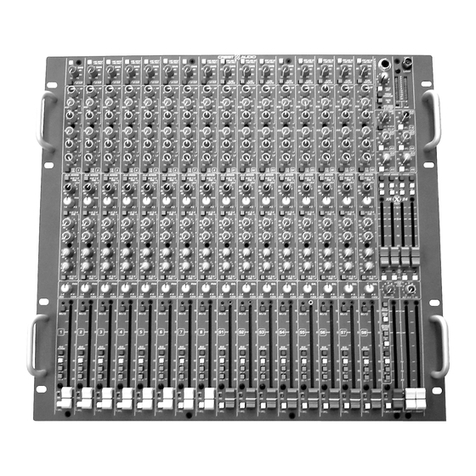
Crest Audio reserves the right to make improvements in manufacturing or design which may affect specifications.
9/4/01
v.1.5
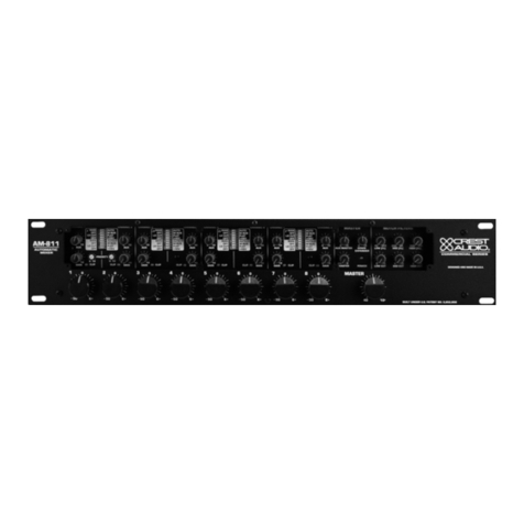
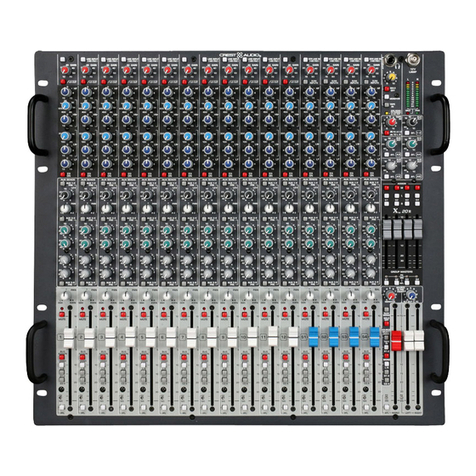
Architects’ & Engineers’ Specifications:
The automatic microphone mixer shall have four
electronically balanced, low noise microphone/line
inputs . Each input shall have its own gain control.
Input 1 and 2 shall each have the patented Priority
Control Circuitry with a priority assign and individ-
ual front panel mute controls. Each channel shall
have individual line level inserts with
enable/bypass switch. Forty-eight Volt phantom
power shall be available on all channels and be
switched on inputs 1 and 2. A security cover is
included, protecting the main controls on the front
panel with marking zones for each input. The mas-
ter section shall be equipped with gain manage-
ment computer logic for seamless operation. There
shall be a balanced mic or line master output with
switch. In addition, there is a master, unbalanced
auxiliary output. There is a master/ slave linking
connection and switch on the back panel for con-
nection to additional AM-411 units, and also the
AM-811 as well as the MM 623 mixer. All audio
connections shall be made with removable “euro”
type connectors. The mixer shall have a frequency
response of 75 Hz to 20 kHz +/- 1 dB. It shall have
an EIN of -128 dBu and the total harmonic distor-
tion shall be less than 0.1% at +4 dBu (22 Hz to 22
kHz BPF). The maximum line output level shall be
+21 dBu (hi-Z load), +18 dBu (600 load). The unit
shall be packaged in a rugged metal chassis 19”
wide by 1.75”high by 9.38”deep. The unit shall
operate from 120 VAC, 60 Hz domestic and from
230VAC, 50/60 Hz export.
test conditions:
reference:
INPUT SPECIFICATIONS
EIN:
preamp gain range:
input impedance:
priority (channels 1 and 2):
phantom power:
input sensitivity:
maximum input level:
common mode rejection:
OUTPUT SPECIFICATIONS
frequency response:
THD:
signal/noise:
output impedance:
nominal output level:
maximum output level:
GENERAL SPECIFICATIONS
channel clip LED:
output level indicators:
power requirements:
dimensions:
weight:
120 Vrms, 60 Hz line voltage maintained throughout testing
0 dBu = 0.775 Vrms
-128 dBu (R s = 150 Ohms), typical
10 dB - 65 dB (MIC inputs)
-13 dB - 44 dB (LINE inputs)
2K Ohms (Mic inputs)
>10K Ohms (LINE inputs)
>10K Ohms (INSERT inputs)
0 dB to 9 dB
+48 Volts
MIC inputs -61 dBu
LINE inputs -40 dBu
INSERT inputs +4 dBu
MIC inputs +12 dBu
LINE inputs +30 dBu
INSERT inputs +21 dBu
>70 dB 20 Hz - 20 kHz
75 Hz (-3 dB) to 20 kHz (-1 dB)
(at +4 dBu; reference: 1 kHz; 75 Hz HPF)
>0.1% at +4 dBu (22 Hz - 30 kHz BPF)
(R s = 150 Ohms; 30 kHz LPF)
>85 dB (all controls fully CCW)
>200 Ohms
LINE level output +4 dBu
MIC level output -26 dBu
INSERT outputs +4 dBu
LINE level output +21 dBu (hi-Z load)
+18 dBu (600 load)
MIC level output -9 dBu (hi-load)
-12 dBu (600 load)
INSERT outputs +21 dBu (hi-Z load)
red LED lights 2 dB before clipping
also lights to indicate mute on channel 1 and 2 inputs
red LED lights 2 dB before clipping
yellow LED lights at +4 dBu
green lights at -16 dBu
120 Vrms, 60 Hz domestic
230 Vrms, 50/60 Hz export
15 Watts nominal
1.75”x 19”x 9.38”(45 mm x 483 mm x 238 mm)
7.5 lbs (3.4 kg)
