manuals.online logo
Brands
  1. Home
  2. •
  3. Brands
  4. •
  5. Crestron
  6. •
  7. Keypad
  8. •
  9. Crestron Zum Series User manual

Crestron Zum Series User manual

ZUMMESH-KPAVBATT
Zūm™ Battery-Powered AV Keypads
Installation Guide
Description
The Crestron®ZUMMESH-KP10AV1BATT, ZUMMESH-KP10AV2BATT,
ZUMMESH-KP10AV3BATT, and ZUMMESH-KP10AV4BATT are AV keypads that expand
the capabilities of a Zūm commercial room lighting system.
NOTE: For simplicity within this guide, the ZUMMESH-KP10AV1BATT,
ZUMMESH-KP10AV2BATT, ZUMMESH-KP10AV3BATT, and ZUMMESH-KP10AV4BATT
are referred to as AV keypad.
NOTE: The AV keypad must be used in conjunction with an AV bridge
(ZUMMESH-AVBRIDGE) that is connected to a local AV control system (both not
included).
The AV keypad controls an AV system by sending serial commands to an AV bridge; the
AV bridge then relays the serial commands from the AV keypad to the AV control system.
Zūm Overview
A basic Zūm commercial lighting system consists of one room with Zūm mesh devices,
i.e., dimmers, switches, keypads, and sensors. The Zūm mesh devices in the room provide
room control and communicate directly with each other without the need for a centralized
gateway or processor.
For centralized control and monitoring from a Crestron control system (not included), use
the ZUMMESH-NETBRIDGE (not included) to connect to the control system.
NOTE: The ZUMMESH-NETBRIDGE requires a compatible J-box device (not included)
to provide power.
For simplied setup of a Zūm lighting system, use the Zūm app on a mobile device.
Additional Resources
Visit the product page on the Crestron website (www.crestron.com)
for additional information and the latest rmware updates. Use a QR
reader application on your mobile device to scan the QR image.
Button Congurations
The ZUMMESH-KP10AV1BATT, ZUMMESH-KP10AV2BATT, ZUMMESH-KP10AV3BATT,
and ZUMMESH-KP10AV4BATT keypads ship with the following button labels.
NOTE: The action of a button press on the AV keypad is determined by the AV control
system.
NOTE: The AV keypad is also available with custom engraving.
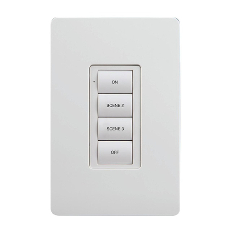
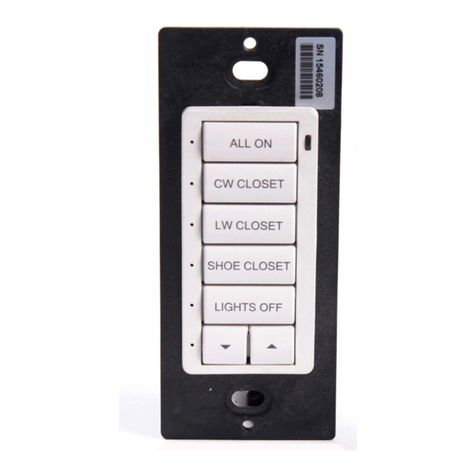
ZUMMESH-KP10AV1BATT Button Labels
The ZUMMESH-KP10AV1BATT is labeled
with ON, AIRMEDIA, LAPTOP, and OFF.
ZUMMESH-KP10AV1BATT
ON
AIRMEDIA
LAPTOP
OFF
ZUMMESH-KP10AV3BATT Button Labels
The ZUMMESH-KP10AV3BATT is labeled
with POWER, AIRMEDIA, LAPTOP, and
CABLE/SAT.
ZUMMESH-KP10AV3BATT
POWER
AIRMEDIA
LAPTOP
CABLE/SAT
ZUMMESH-KP10AV2BATT Button Labels
The ZUMMESH-KP10AV2BATT is labeled
with ON, AIRMEDIA, LAPTOP, OFF, 3(up),
and 4(down).
ZUMMESH-KP10AV2BATT
ON
AIRMEDIA
LAPTOP
OFF
ZUMMESH-KP10AV4BATT Button Labels
The ZUMMESH-KP10AV4BATT is labeled
with POWER, AIRMEDIA, LAPTOP,
CABLE/SAT, 3(up), and 4(down).
ZUMMESH-KP10AV4BATT
POWER
AIRMEDIA
LAPTOP
CABLE/SAT
Installation
NOTE: Observe the following points.
• Codes: Install in accordance with all local and national electrical codes.
• Temperature: For use where temperatures are between 32° to 104 °F
(0° to 40 °C).
• Electrical Boxes: Several devices can be installed in one electrical box
(multigang). For a smooth appearance, install a one-piece multigang faceplate (not
included).
Mount the AV keypad to a single-gang box or directly to a at surface using double-sided
tape.
Mount in a Single-Gang Box
Secure the AV keypad to a single-gang box using the two supplied screws. Attach a
decorator-style faceplate (not supplied).
AV Keypad Mounting
Two screws are supplied
for mounting the keypad to
a back box.
Mount with Double-Sided Tape
Secure the AV keypad to a at, clean surface using the supplied double-sided tape.
1. Clean the mounting surface with a light cleaning agent that does not leave a residue.
2. Remove the backing of one piece of double-sided tape, and apply it to the back of the
keypad. Repeat for the other piece of double-sided tape.
Two pieces of tape are supplied
to mount the keypad without a
backbox.
3. Ensure that the keypad is vertical, and press it against the wall. Press rmly to ensure
that the keypad is properly secured to the wall.
CAUTION: Removing the keypad after installation may damage the mounting
surface.
Press rmly to ensure
proper adhesion.
Battery
Prior to operation, remove the battery tab to turn on the keypad.
Remove the battery tab prior
to operation.
Battery Replacement
WARNING: Refer to the following warnings before changing the batteries.
• Chemical burn hazard, do not ingest batteries.
• This product contains coin cell batteries. If a coin cell battery is swallowed, it can
cause severe internal burns in just 2 hours and can lead to death.
• Keep new and used batteries away from children. If the battery compartment does
not close securely, stop using the product and keep it away from children.
• If you think batteries have been swallowed or placed inside any part of the body,
seek immediate medical attention.
CAUTION: The battery used in this device may present a risk of re or chemical burn
if mistreated. Do not recharge, disassemble, heat above 212°F (100°C), or incinerate.
Replace batteries with an identical CR2450 only. Use of another battery may present a
risk of re or explosion.
To remove the battery, insert a pin or paper clip into the slot on the left side of the keypad.
The battery slides out of the opposite side of the keypad.
To remove the battery,
insert a pin or paper clip
into the hole on the side.
NOTE: The battery must be inserted properly.
NOTE: The keypad will not operate if the battery is inserted incorrectly.
To install a new battery, insert the battery into the battery slot. The — terminal faces away
from the wall.
Battery CR2032
(—) toward the front of the
keypad
Button Functions
The AV keypad functions by sending a serial command to the AV bridge when a button
is pressed. The serial command is comprised of the button press type, the button
number, the AVID, and the keypad serial number. For additional information, refer to the
ZUMMESH-AVBRIDGE Installation Guide (Doc. 7916) at www.crestron.com/manuals.
NOTE: After the AV bridge receives the command, the AV bridge sends the command
to the AV control system.
The AV keypad command format:
!button.[tap|hold|release].[button].[id].[SN]
• tap|hold|release - the type of button press
• button - the button number that is pressed
• id - the AVID of the keypad
• SN - the serial number of the keypad
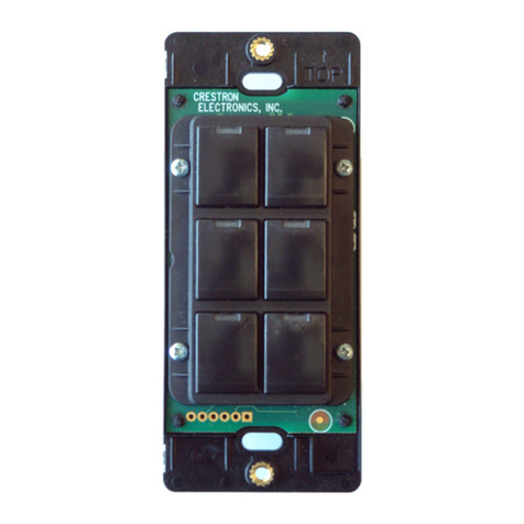
The illustration that follows lists the button locations for the two styles of AV keypads.
Button 1
Button 2
Button 3
Button 4
Button 5
Button 6
Button 1
Button 2
Button 3
Button 4
Basic Room Setup
The Zūm mesh devices in the room communicate directly with each other without the
need for a centralized gateway or processor.
To set up a new single-room Zūm system, do the following:
Step 1a: Create a new single-room Zūm system.
Step 2: Add Zūm mesh devices to the room.
Step 3: Finish creating the single-room Zūm system.
To modify an existing Zūm system, do the following:
Step 1b: Place the system in Joining mode.
Step 2: Add Zūm mesh devices to the room.
Step 3: Finish creating the single-room Zūm system.
Step 1a – Creating a Single-Room Zūm System
To create a new single-room Zūm system, rst form a new room using an ac-powered Zūm
device.
NOTE: A room can be created only from an ac-powered device.
NOTE: This can be performed on only one device in the room.
NOTE: The device that is used to create the room is automatically added to the room.
The device does not need to be added to the room.
Start a New Single-Room System with a Keypad, Dimmer, or Switch
Press the bottom button 5 times, and then press and hold the bottom button for
2 seconds. If the device is not factory fresh, hold the button for 10 seconds. Release
the button when the LED lights. The LED lights for 3 seconds and then slowly blinks to
indicate that the room is in Joining mode and that other devices can join the room.
2s or 10s
Start a Single-Room System with a J-box Device
Press the SETUP button 5 times, and then press and hold the SETUP button for
2 seconds. If the device is not factory fresh, hold the button for 10 seconds. Release
the button when the LED lights. The LED lights for 3 seconds and then slowly blinks to
indicate that the room is in Joining mode and that other devices can join the room.
TEST
SETUP
2s or 10s
Step 1b – Expanding an Existing Single-Room Zūm System
To allow other devices to join the room, place the single-room Zūm system into Joining
mode. Joining mode can be enabled from any ac-powered device or battery keypad that
is already part of the room.
Expand a Single-Room Zūm System Using a Keypad
To enter Joining mode, press and hold both the top and bottom buttons for 5 seconds,
wait for the LED to light, and then press the top button once and the bottom button once.
5s
Expand a Single-Room Zūm System Using a J-box Device
To enter Joining mode, press the SETUP button 2 times, and then press the TEST button.
Pressing any button on a device that is part of the network takes the system out of joining
mode. Joining mode ends automatically after 4 minutes.
TEST
SETUP
TEST
SETUP
Step 2 - Adding Zūm Mesh Devices to the Room
Adding Zūm mesh devices to a room is quick and easy. Add devices to the room when the
room is in Joining mode. Joining mode is automatically enabled after a single-room Zūm
system is started (see Step 1a). Joining mode can also be enabled manually (see Step 1b).
The LEDs on all ac-powered devices in the system blink when the system is in Joining
mode.
NOTE: A Zūm mesh device can belong to only one room.
NOTE: The Zūm mesh device used to create the room is already part of the network. It
does not need to be added to the network.
To add a dimmer or switch to the room, press the top button 3 times, and then press and
hold the top button for 2 seconds. If the device is not factory fresh, hold the button for 10
seconds. Release the button when the LED lights. The LED blinks slowly to indicate that it is
part of the room and that the room is still in Joining Mode.
2s or 10s
Step 3 - Finishing the Single-Room Zūm System
Press any button on a device that has already joined the network to end the setup process
(e.g., the top button of a keypad or the SETUP button of a J-box device that is blinking its
LED).
TEST
SETUP
Factory Reset
Perform a factory reset when the device is removed from the network or to remove the
conguration settings. The device must also be factory reset if the device is being moved to
a different system.
NOTE: New-in-box devices do not need to be factory reset before joining a system.
To factory reset a dimmer or switch, press and hold the top and bottom buttons for
5 seconds until the LED lights, and then release both buttons. Then, press and hold the
bottom button for 10 seconds until the LED lights.
Troubleshooting
The following provides corrective actions for possible trouble situations. If further assistance
is required, please contact a Crestron customer service representative.
TROUBLE POSSIBLE CAUSE(S) ACTION
The AV keypad is not
controlling the lights in the
room.
The AV bridge is not joined
to the same room as the AV
keypad.
Verify that the AV bridge is
joined to the same room as
the AV keypad.
The AV bridge is not
receiving the serial packet
or not transmitting the
serial packet to the AV
control system.
Verify that the green Tx
LED lights on the AV bridge
when a button on the AV
keypad is pressed. The
Tx LED indicates that a
message is being received
from the AV keypad and
that a serial packet is
being transmitted to the AV
control system.
The AV control system is
not congured properly.
Verify that the program
running in the AV control
system is decoding and
acting on the serial packet
from the AV bridge.
Messages from the
ZUMMESH-AVBRIDGE
are not getting to the AV
control system
The AV bridge is not
properly connected to the
AV control system.
Check the serial
connections to the AV
control system.
If the AV bridge is
connected to RS-232 on
a control system and the
USB port on a computer,
serial data from the AV
bridge is not transmitted
over the RS-232 port.
The AV keypad LED lights
red when a button is
pressed.
The battery is low. Replace the battery.
Control from the AV keypad
is intermittent.
There is poor
communication between
devices in the room.
Verify that the range
between the AV keypad
and the other ac-powered
devices in the room is less
than 50 feet.
Verify that the range
between the AV bridge
and the other ac-powered
devices in the room is less
than 50 feet.
Verify that there are no
Wireless Access Points
(WAPs) within 10 feet of the
AV bridge.
This product is Listed to applicable UL®Standards and requirements tested by Underwriters
Laboratories Inc.
Ce produit est homologué selon les normes et les exigences UL applicables par Underwriters
Laboratories Inc.
Federal Communications Commission (FCC) Compliance Statement
This device complies with part 15 of the FCC Rules. Operation is subject to the following two conditions:
(1) This device may not cause harmful interference, and (2) this device must accept any interference
received, including interference that may cause undesired operation.
CAUTION: Changes or modications not expressly approved by the manufacturer responsible for
compliance could void the user’s authority to operate the equipment.
NOTE: This equipment has been tested and found to comply with the limits for a Class A digital device,
pursuant to part 15 of the FCC Rules. These limits are designed to provide reasonable protection against
harmful interference when the equipment is operated in a commercial environment. This equipment
generates, uses, and can radiate radio frequency energy and, if not installed and used in accordance
with the instruction manual, may cause harmful interference to radio communications. Operation of
this equipment in a residential area is likely to cause harmful interference in which case the user will be
required to correct the interference at his own expense.
Industry Canada (IC) Compliance Statement
CAN ICES-3(A)/NMB-3(A)
The product warranty can be found at www.crestron.com/warranty.
The specic patents that cover Crestron products are listed at www.crestron.com/legal/patents.
Certain Crestron products contain open source software. For specic information, please visit
www.crestron.com/opensource.
Crestron, the Crestron logo, and Zūm are either trademarks or registered trademarks of Crestron
Electronics, Inc. in the United States and/or other countries. UL and the UL logo are either trademarks
or registered trademarks of Underwriters Laboratories, Inc. in the United States and/or other countries.
Other trademarks, registered trademarks, and trade names may be used in this document to refer to
either the entities claiming the marks and names or their products. Crestron disclaims any proprietary
interest in the marks and names of others. Crestron is not responsible for errors in typography or
photography.
This document was written by the Technical Publications department at Crestron.
©2017 Crestron Electronics, Inc.
Crestron Electronics, Inc. Installation Guide - DOC. 8204A
15 Volvo Drive Rockleigh, NJ 07647 (2049142)
Tel: 888.CRESTRON 09.17
Fax: 201.767.7576 Specications subject to
www.crestron.com change without notice.

Other Crestron Keypad manuals

Crestron Cameo C2NI-CB Series User manual

Crestron

Crestron Cameo C2NI-CB Series User manual

Crestron C2NI-AG Creslight II How to use

Crestron

Crestron C2NI-AG Creslight II How to use

Crestron CNX-B12 How to use

Crestron

Crestron CNX-B12 How to use

Crestron Cameo INET-CBDEX Series How to use

Crestron

Crestron Cameo INET-CBDEX Series How to use

Crestron GLPPA-KP User manual

Crestron

Crestron GLPPA-KP User manual

Crestron ZUMLINK-KP User manual

Crestron

Crestron ZUMLINK-KP User manual

Crestron CLWI-KPLEX User manual

Crestron

Crestron CLWI-KPLEX User manual

Crestron HTT-B10EX How to use

Crestron

Crestron HTT-B10EX How to use

Crestron black nova AXES Series User manual

Crestron

Crestron black nova AXES Series User manual

Crestron CLWI-KPLCN User manual

Crestron

Crestron CLWI-KPLCN User manual

Crestron Lutron CNWM-LU12 How to use

Crestron

Crestron Lutron CNWM-LU12 How to use

Crestron ZUM  ZUMMESH-KP User manual

Crestron

Crestron ZUM ZUMMESH-KP User manual

Crestron CN-WP12FW User manual

Crestron

Crestron CN-WP12FW User manual

Crestron C2N-DB12 How to use

Crestron

Crestron C2N-DB12 How to use

Crestron CNWM-10A User manual

Crestron

Crestron CNWM-10A User manual

Crestron Zum ZUMMESH-KPBATT User manual

Crestron

Crestron Zum ZUMMESH-KPBATT User manual

Crestron Cameo C2N-CBD-P Original operating instructions

Crestron

Crestron Cameo C2N-CBD-P Original operating instructions

Crestron INET-CBDEX-E Original operating instructions

Crestron

Crestron INET-CBDEX-E Original operating instructions

Crestron HZ-BTN User manual

Crestron

Crestron HZ-BTN User manual

Crestron AirMedia ZUMMESH-KP10AMBATT User manual

Crestron

Crestron AirMedia ZUMMESH-KP10AMBATT User manual

Crestron C2N-LCDB3 Dimensional drawing

Crestron

Crestron C2N-LCDB3 Dimensional drawing

Crestron C2N-DBF12 How to use

Crestron

Crestron C2N-DBF12 How to use

Crestron ZUMMESH-KP10ABATT User manual

Crestron

Crestron ZUMMESH-KP10ABATT User manual

Crestron Cameo C2N-CBD-P Quick start guide

Crestron

Crestron Cameo C2N-CBD-P Quick start guide

Popular Keypad manuals by other brands

SunVote S53 user manual

SunVote

SunVote S53 user manual

Marmitek WK820 user manual

Marmitek

Marmitek WK820 user manual

Hama WK300 Operating	 instruction

Hama

Hama WK300 Operating instruction

Bosch FMR-DACT-KEYPAD Operation instructions

Bosch

Bosch FMR-DACT-KEYPAD Operation instructions

EAST COAST KPX7 Coding Instructions

EAST COAST

EAST COAST KPX7 Coding Instructions

MAASLAND CS500 installation instructions

MAASLAND

MAASLAND CS500 installation instructions

GE KTD-405 quick guide

GE

GE KTD-405 quick guide

Speco SG-100 instruction manual

Speco

Speco SG-100 instruction manual

Wittkopp FinKey user manual

Wittkopp

Wittkopp FinKey user manual

DoorHan KeyPad installation manual

DoorHan

DoorHan KeyPad installation manual

Chamberlain WKP5LM3 manual

Chamberlain

Chamberlain WKP5LM3 manual

Bosch D223TD installation instructions

Bosch

Bosch D223TD installation instructions

Elkron MP504 Quick use guide

Elkron

Elkron MP504 Quick use guide

rako RNC instruction manual

rako

rako RNC instruction manual

S4A TF1 user manual

S4A

S4A TF1 user manual

CDVI PROFIL100EINT installation manual

CDVI

CDVI PROFIL100EINT installation manual

NAPCO Gemini GEM-DXRP3 operating guide

NAPCO

NAPCO Gemini GEM-DXRP3 operating guide

MCS KEYPAD-OEM installation instructions

MCS

MCS KEYPAD-OEM installation instructions

manuals.online logo
manuals.online logoBrands
  • About & Mission
  • Contact us
  • Privacy Policy
  • Terms and Conditions

Copyright 2025 Manuals.Online. All Rights Reserved.