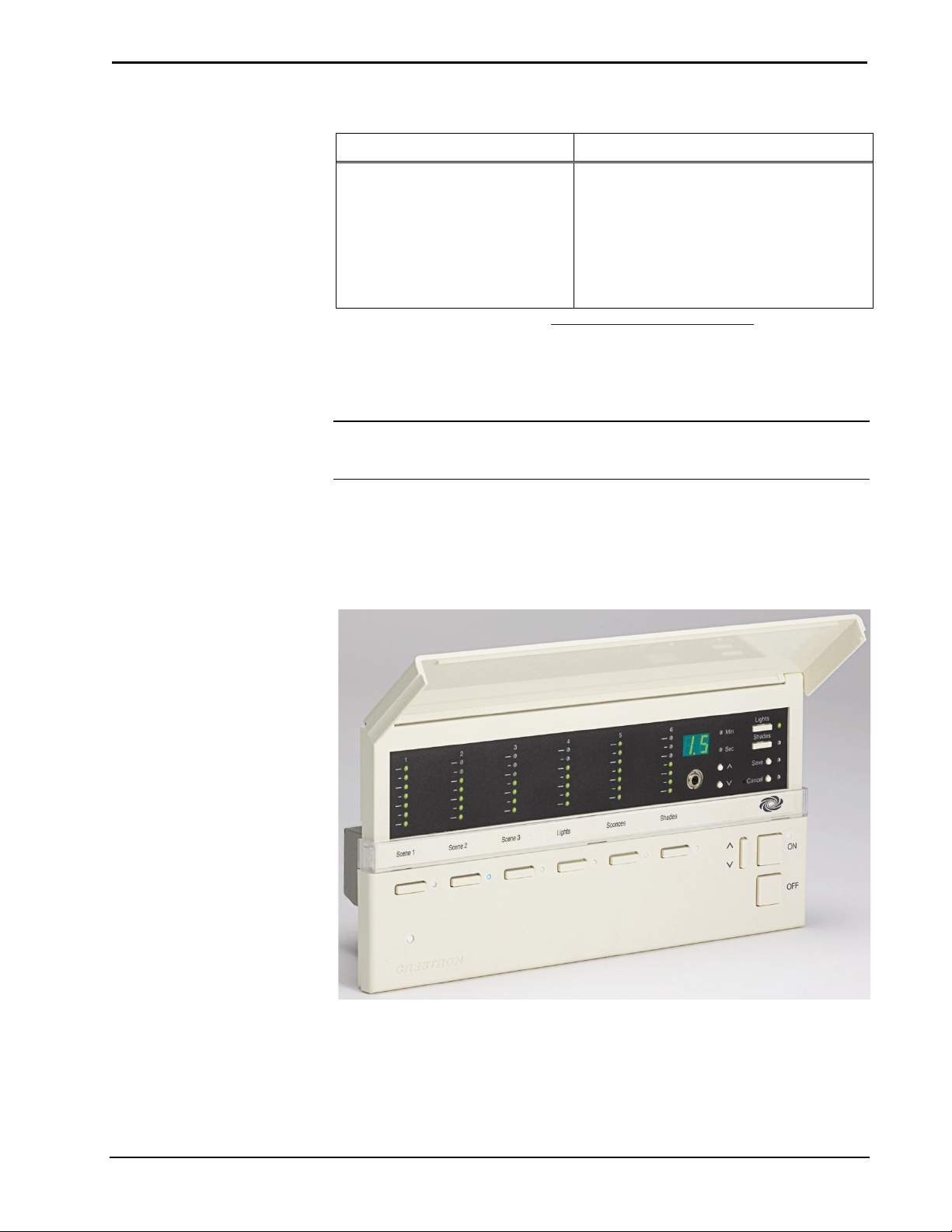
Crestron CLS-C6/C6M & CLSI-C6/C6M iLux Integrated Lighting System
Operations Guide – DOC. 6347E Contents •i
Contents
iLux Integrated Lighting System: CLS-C6/C6M & CLSI-C6/C6M 1
Introduction ............................................................................................................................... 1
Features and Functions ................................................................................................1
Specifications ..............................................................................................................4
Physical Description....................................................................................................6
Setup ........................................................................................................................................ 10
Network Wiring......................................................................................................... 10
Identity Code ............................................................................................................. 10
Installation ................................................................................................................. 10
Configuring the CLS-C6.......................................................................................................... 11
Configuring With Front Panel Controls .................................................................... 11
Configuring with iLux Designer................................................................................ 23
Console Command Settings ...................................................................................... 25
Replacing the Function Button Label ........................................................................ 26
Programming Software ............................................................................................................ 28
Earliest Version Software Requirements for the PC ................................................. 28
Programming with SystemBuilder ............................................................................ 28
Programming with D3 Pro......................................................................................... 28
Programming with SIMPL Windows ........................................................................ 29
Uploading and Upgrading........................................................................................................ 31
Establishing Communication..................................................................................... 31
Programs and Firmware ............................................................................................ 32
Operation ................................................................................................................................. 33
Button Types ............................................................................................................. 33
IR Receiver................................................................................................................ 36
Occupancy Sensing ................................................................................................... 36
Override Mode .......................................................................................................... 36
Load Shedding (Demand Response) ......................................................................... 37
Building Management System (BMS) Interface ....................................................... 37
Problem Solving ...................................................................................................................... 41
Troubleshooting......................................................................................................... 41
Check Network Wiring.............................................................................................. 41
Reference Documents................................................................................................ 42
Further Inquiries ........................................................................................................ 42
Future Updates .......................................................................................................... 43
Appendix A: Supported Devices ............................................................................................ 44
Keypads..................................................................................................................... 44
Shade Controllers ...................................................................................................... 46
Touch Panels ............................................................................................................. 46
Appendix B: Console Commands............................................................................................ 54
Appendix C: RS-232 Commands ............................................................................................ 58
Command Format...................................................................................................... 58
Adding C2N-IO Device to CLS-C6 .......................................................................... 62
Echo Control Command ............................................................................................ 62
Light Zone Commands .............................................................................................. 62
Shade Group Commands........................................................................................... 65