manuals.online logo
Brands
  1. Home
  2. •
  3. Brands
  4. •
  5. Crestron
  6. •
  7. Speakers System
  8. •
  9. Crestron Saros SB-200-P Dimensional drawing

Crestron Saros SB-200-P Dimensional drawing

DO GUIDE
3. Install the included thumb screws on the rear of the sound bar.
4. Connect the sound bar as described in “DO Connect the Device.”
5. Place the sound bar against the wall, above the mounting bracket, and lower the sound bar until
the thumb screws rest in the mounting bracket.
DO Connect the Device
Make the necessary connections as called out in the diagram below. Connect power last.
NOTE: Connect only one input.
NOTE: If using the included RCA®cable for connecting the UNBALANCED port, use the right-
angled connectors to allow the cable to t between the wall and the sound bar.
DO Use the Device
Move the switch located above the 100–240V~ 50/60Hz 50W port to turn on the sound bar. The PWR
LED lights, and sound from the connected source is produced.
If an audio signal is not present for approximately 20 minutes, the sound bar switches to a low power
idle state. The sound bar resumes normal operation when an audio signal is detected.
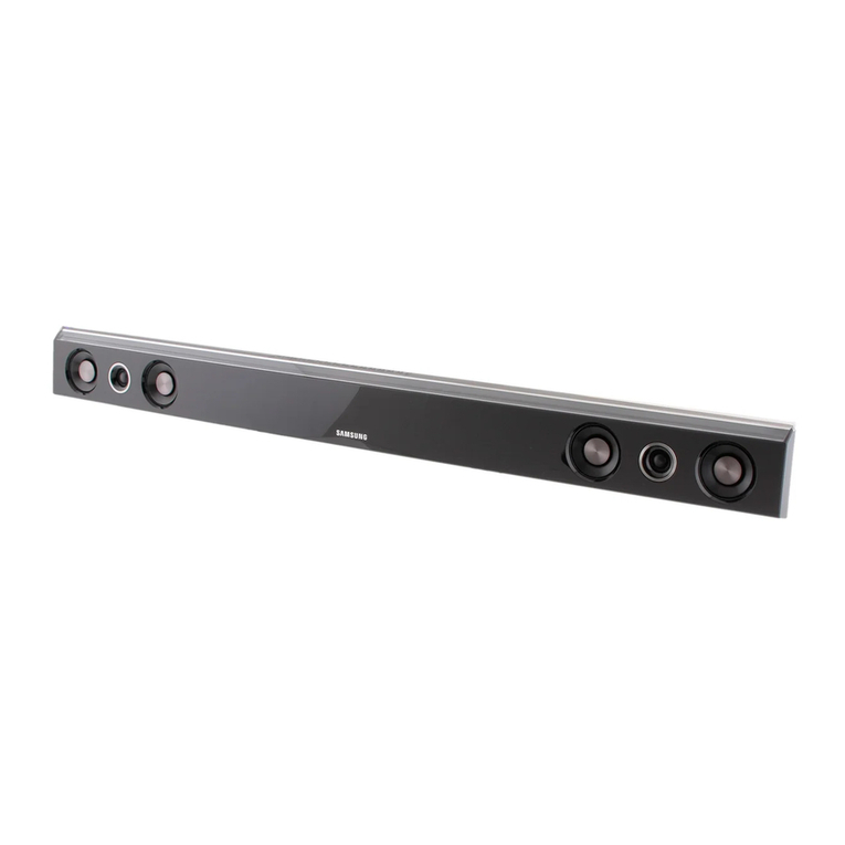
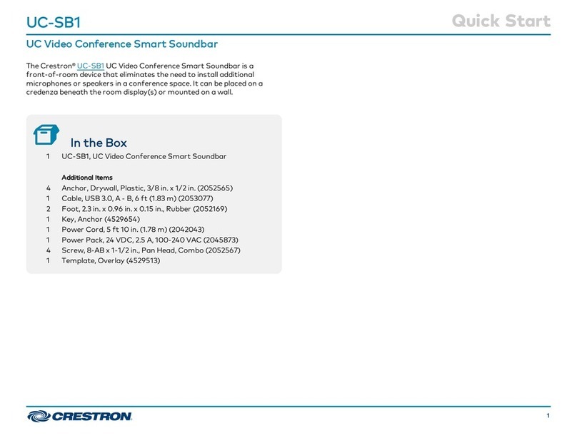
SAROS SB-200-P
Saros®Sound Bar 200, Powered
DO Install the Device
The Saros®Sound Bar can be installed as part of a Crestron RL®2 Group Collaboration system or
on a wall as part of any integrated audio system. With the balanced and unbalanced inputs, the
sound bar can work with any audio system.
In a Crestron RL System
Use the included thumb screws to attach the sound bar to the sound bar bracket. Refer to the
quickstart included with the Crestron RL Group Collaboration system for details.
On a Wall
1. Place the mounting bracket on the wall.
NOTE: Use a laser level or snap a chalk line to mark the location of the bracket.
2. Secure the bracket to the wall with hardware that is appropriate for the mounting surface.
NOTE: If a stud cannot be located, use the screwholes located adjacent to each keyhole slot.
DO Check the Box
QTY PRODUCT COLOR PART NUM.
1Bracket, Mounting 2048193
1Cable, RCA®, Right-Angle, 6' (1.83 m) Black 2047013
1Connector, 5-Pin 2047025
1 Power Cord, 6' (1.83 m) Black 2047024
2 Screw, 6-32, Thumb 2047009
DIMENSION INCHES MILLIMETERS
A26.8 680
B23.3 592
C21.3 540
D18.6 472
E16.5 420
F13.9 352
G11.8 300
H9.1 232
I7.1 180
J 4.4 112
K2.4 60
L0.3 8
A
BCDEFGHIJKL
BALANCED AUDIO INPUT:
From balanced audio source
UNBALANCED AUDIO INPUT:
From unbalanced audio source
100–240V~ 50/60Hz 50W:
From ac power outlet
DO GUIDE DOC. 7508D (2045962) 08.17
Specications subject to change without notice.
DO Learn More
Visit the website for additional information and the latest rmware updates. To learn
more about this product, use a QR reader application on your mobile device to scan
the QR image.
Crestron Electronics
15 Volvo Drive, Rockleigh, NJ 07647
888.CRESTRON | www.crestron.com
As of the date of manufacture, the product has been tested and found to comply with specications for CE marking.
Federal Communications Commission (FCC) Compliance Statement
This device complies with part 15 of the FCC Rules. Operation is subject to the following two conditions:
(1) This device may not cause harmful interference, and (2) this device must accept any interference received, including interference
that may cause undesired operation.
CAUTION:Changes or modications not expressly approved by the manufacturer responsible for compliance could void the
user’s authority to operate the equipment.
NOTE: This equipment has been tested and found to comply with the limits for a Class B digital device, pursuant to part 15 of the
FCC Rules. These limits are designed to provide reasonable protection against harmful interference in a residential installation.
This equipment generates, uses and can radiate radio frequency energy and, if not installed and used in accordance with the
instructions, may cause harmful interference to radio communications. However, there is no guarantee that interference will not
occur in a particular installation.
If this equipment does cause harmful interference to radio or television reception, which can be determined by turning the
equipment off and on, the user is encouraged to try to correct the interference by one or more of the following measures:
• Reorient or relocate the receiving antenna.
• Increase the separation between the equipment and receiver.
• Connect the equipment into an outlet on a circuit different from that to which the receiver is connected.
• Consult the dealer or an experienced radio/TV technician for help.
Industry Canada (IC) Compliance Statement
CAN ICES-3(B)/NMB-3(B)
Electrical Connection
“This product must be connected to an earthed mains socket-outlet.”
• Finland: “Laite on liitettävä suojamaadoituskoskettimilla varustettuun pistorasiaan.”
• Norway: “Apparatet må tilkoples jordet stikkontakt.”
• Sweden: “Apparaten skall anslutas till jordat uttag.”
The specic patents that cover Crestron products are listed at www.crestron.com/legal/patents. The product warranty can be found at www.crestron.com/warranty.
Certain Crestron products contain open source software. For specic information, please visit www.crestron.com/opensource.
Crestron, the Crestron logo, Crestron RL, and Saros are either trademarks or registered trademarks of Crestron Electronics, Inc. in the United States and/or other countries. RCA is either a
trademark or registered trademark of VOXX International Corporation in the United States and/or other countries. Other trademarks, registered trademarks, and trade names may be used
in this document to refer to either the entities claiming the marks and names or their products. Crestron disclaims any proprietary interest in the marks and names of others. Crestron is not
responsible for errors in typography or photography.
This document was written by the Technical Publications department at Crestron.
©2017 Crestron Electronics, Inc.

Other Crestron Speakers System manuals

Crestron UC-SB1-CAM-FLEX User manual

Crestron

Crestron UC-SB1-CAM-FLEX User manual

Crestron UC-SB1 User manual

Crestron

Crestron UC-SB1 User manual

Crestron Surround Sound Tuning Kit User manual

Crestron

Crestron Surround Sound Tuning Kit User manual

Crestron UC-SB1-CAM-L-FLEX User manual

Crestron

Crestron UC-SB1-CAM-L-FLEX User manual

Crestron UC-SB1 User manual

Crestron

Crestron UC-SB1 User manual

Crestron SAROS SB-200-P-B Dimensional drawing

Crestron

Crestron SAROS SB-200-P-B Dimensional drawing

Crestron UC-SB1 User manual

Crestron

Crestron UC-SB1 User manual

Crestron UC-SB1-CAM User manual

Crestron

Crestron UC-SB1-CAM User manual

Popular Speakers System manuals by other brands

Sven SB-700 manual

Sven

Sven SB-700 manual

Polk Mono MagniFi Mini quick start guide

Polk Mono

Polk Mono MagniFi Mini quick start guide

Munro Sonic EGG 150 Operation manual

Munro Sonic

Munro Sonic EGG 150 Operation manual

Phonic SAFARI 2000 SYS3 user manual

Phonic

Phonic SAFARI 2000 SYS3 user manual

Bose Acoustimass AM293692 owner's guide

Bose

Bose Acoustimass AM293692 owner's guide

Yamaha YSP-1600 Quick reference guide

Yamaha

Yamaha YSP-1600 Quick reference guide

Danley DSLP48 user manual

Danley

Danley DSLP48 user manual

Ozaki EM93626 Instruction

Ozaki

Ozaki EM93626 Instruction

BST PWA320 instruction manual

BST

BST PWA320 instruction manual

Sony SS-CCP500 Service manual

Sony

Sony SS-CCP500 Service manual

Harman JBL EON ONE Compact user guide

Harman

Harman JBL EON ONE Compact user guide

Toa SR-F08 Service manual

Toa

Toa SR-F08 Service manual

Lab.gruppen PLM+ Series quick start guide

Lab.gruppen

Lab.gruppen PLM+ Series quick start guide

Philips HTL1170B/F7 quick start guide

Philips

Philips HTL1170B/F7 quick start guide

LG QP5W Simple manual

LG

LG QP5W Simple manual

LG SL8Y Simple manual

LG

LG SL8Y Simple manual

Pyle PPHP1299WU user manual

Pyle

Pyle PPHP1299WU user manual

Sven PS-47 user manual

Sven

Sven PS-47 user manual

manuals.online logo
manuals.online logoBrands
  • About & Mission
  • Contact us
  • Privacy Policy
  • Terms and Conditions

Copyright 2025 Manuals.Online. All Rights Reserved.