DO GUIDE
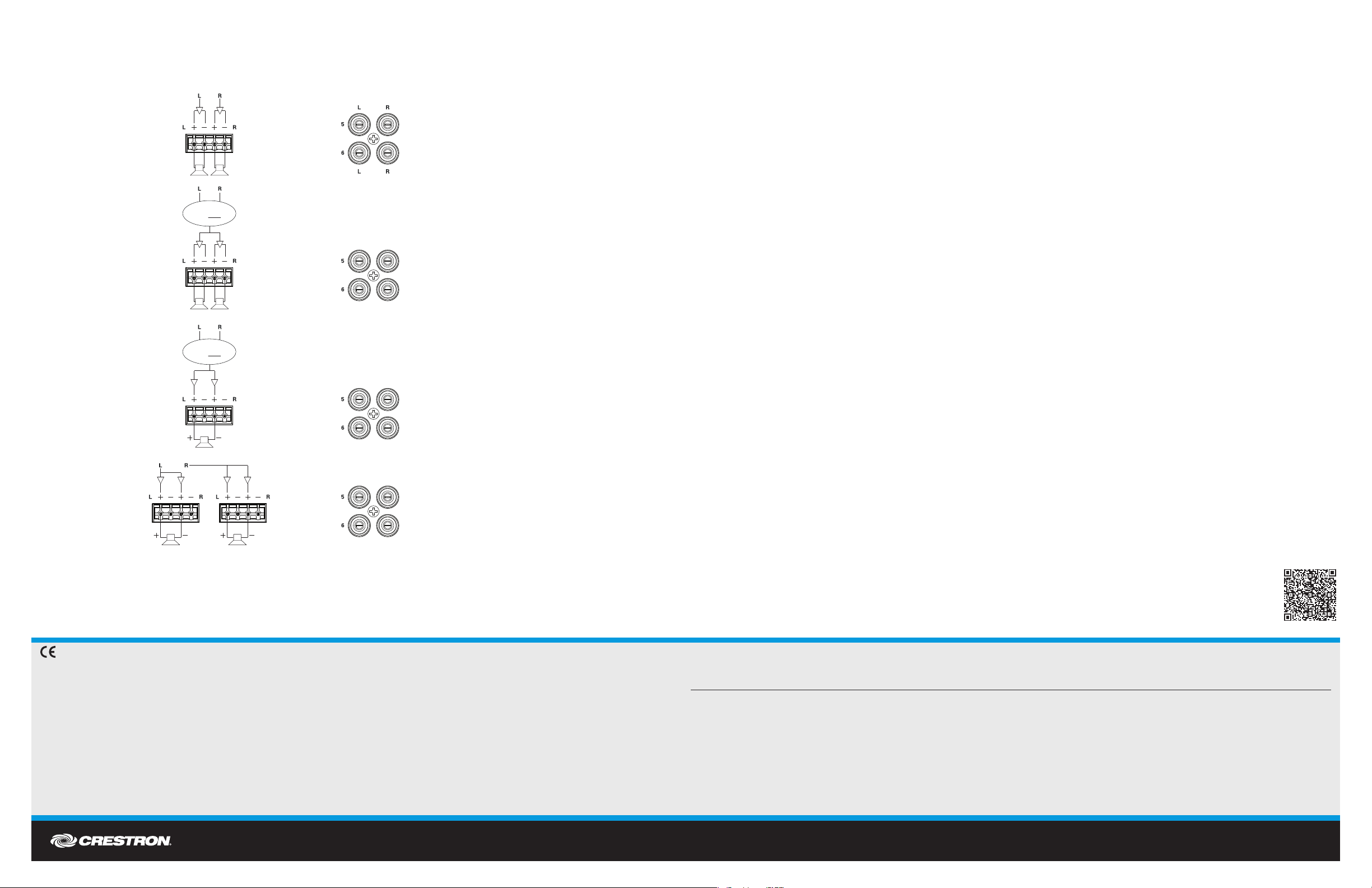
Speakers can be connected for stereo, mono, bridged mono, or bridged stereo operation as shown below.
The mode of operation is set in Crestron programming software. Each zone’s mode of operation can be set independently (except when a zone is part of a
bridged pair).
CAUTION: When set for bridged operation (stereo ormono), triple the power (up to 150 watts into 8 ohm speakers only) output can be delivered to the
connected speaker(s). Make sure all connected speakers are properly rated for the increased power output.
DOC. 7622A (2039619) 10.14
Specications subject to change without notice.
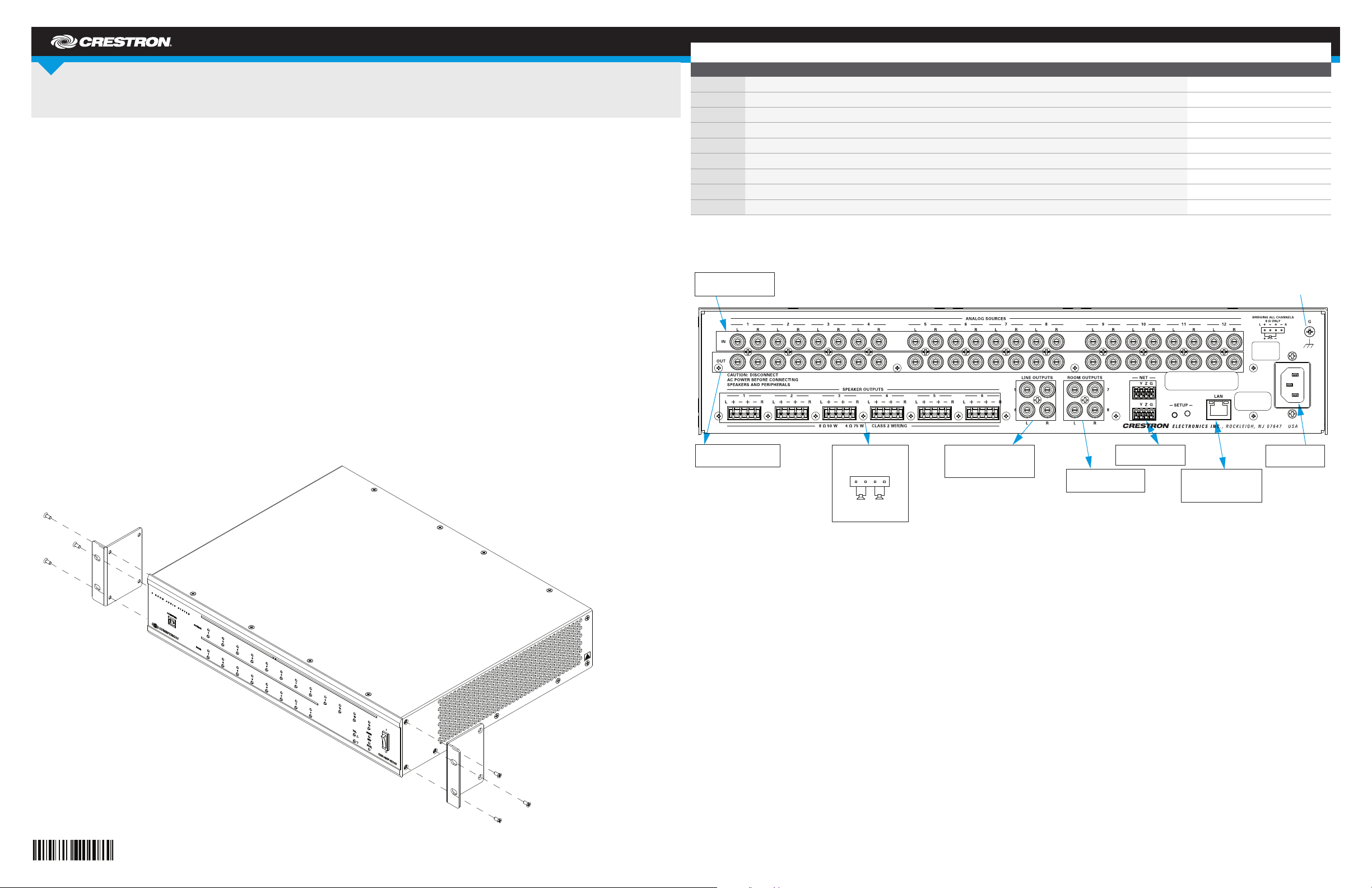
DO Use the Device
Turn the Amplier On or Off
To turn the amplier on, move the front panel switch to the ON position.
To turn the amplier off, move the front panel switch to the OFF position.
Select a Source
To select a source for distribution, press the desired SOURCE button. If a room is connected to the selected source, its LED lights.
NOTE: If a room is in Volume Control mode, press a SOURCE button to exit the mode.
Select a Room
Once a source is selected, press any ROOM button that is to receive the selected source. The room is connected to the selected source and its LED lights.
To remove a room from the selected source, press the ROOM button of a connected room. The LED turns off.
NOTE: If a room is in Volume Control mode, press a ROOM button to exit the mode.
NOTE: If the outputs of the C2N(I)-AMP-6X100 are bridged, the ROOM 1 button acts in unison with the ROOM 2 button, the ROOM 3 button acts in unison
with the ROOM 4 button, and the ROOM 5 button acts in unison with the ROOM 6 button. Similarly, the ROOM 1 LED acts in unison with the ROOM 2 LED,
the ROOM 3 LED acts in unison with the ROOM 4 LED, and the ROOM 5 LED acts in unison with the ROOM 6 LED.
Volume Control Mode
The volume level of a connected room can be controlled when the room is in Volume Control mode. Perform the following to switch to Volume Control mode:
1. Press and hold the ROOM button of the room to be controlled for 2 seconds.
NOTE: To adjust the volume of a bridged stereo pair, select ROOM 1 for SPEAKER OUTPUTS 1 and 2, ROOM 3 for SPEAKER OUTPUTS 3 and 4, or
ROOM 5 for SPEAKER OUTPUTS 5 and 6.
• Press or to change the volume in 1 dB increments.
•
If the maximum volume or minimum volume is reached, all of the front panel LEDs blink three times.
NOTE: If or is not pressed for 10 seconds, the amplifier automatically exits Volume Control mode.
2. Press the ROOM button again to exit Volume Control mode.
As of the date of manufacture, the product has been tested and found to comply with specications for CE marking.
Federal Communications Commission (FCC) Compliance Statement
This device complies with part 15 of the FCC Rules. Operation is subject to the following conditions:
(1) This device may not cause harmful interference and (2) this device must accept any interference received, including interference that may cause undesired operation.
Caution: Changes or modications not expressly approved by the manufacturer responsible for compliance could void the user’s authority to operate the equipment.
Note: This equipment has been tested and found to comply with the limits for a Class B digital device, pursuant to part 15 of the FCC Rules. These limits are designed to provide
reasonable protection against harmful interference in a residential installation. This equipment generates, uses and can radiate radio frequency energy and, if not installed and
used in accordance with the instructions, may cause harmful interference to radio communications. However, there is no guarantee that interference will not occur in a particular
installation.
If this equipment does cause harmful interference to radio or television reception, which can be determined by turning the equipment off and on, the user is encouraged to try to
correct the interference by one or more of the following measures:
• Reorient or relocate the receiving antenna
• Increase the separation between the equipment and receiver
• Connect the equipment into an outlet on a circuit different from that to which the receiver is connected
• Consult the dealer or an experienced radio/TV technician for help
Industry Canada (IC) Compliance Statement
CAN ICES-3(B)/NMB-3(B)
The specic patents that cover Crestron products are listed at www.patents.crestron.com. Product warranty can be found at www.crestron.com/warranty.
Crestron, the Crestron logo, and Cresnet are either trademarks or registered trademarks of Crestron Electronics, Inc., in the United States and/or other countries. Other trademarks, registered trademarks, and trade names may be used in this document to refer to either the entities claiming the marks
and names or their products. Crestron disclaims any proprietary interest in the marks and names of others. Crestron is not responsible for errors in typography or photography.
This document was written by the Technical Publications department at Crestron.
©2014 Crestron Electronics, Inc.
DO Learn More
Check the website for the latest rmware updates.
Crestron Electronics 15 Volvo Drive, Rockleigh, NJ 07647
888.CRESTRON | www.crestron.com
Zone 5 and 6 Line Output Function
(If a Source is Connected to Outputs 5 or 6)
Speaker Connections
Normal Stereo Mode
Mono Mode
M M
M M
Mono Operation
M= L + R
2
Bridged Mono Mode
M N/A
M N/A
Mono Operation
M= L + R
2
Bridged Stereo Mode
(Two Zone Outputs Required)
N/AR
L N/A
Hold or for more than 1 second, to ramp the volume up or down in 1 dB/0.1 second increments.

-AMP-4X100 User manual")


-24X8 User manual")