Crime Guard 328i3 User manual

INSTALLATION MANUAL
for models
COPYRIGHT 1999:OMEGARESEARCH&DEVELOPMENT,INC.
328i3/ 533i3/ 745i3

InstallationConsiderations
Before Starting The Installation ........................................................ 4
Mounting The Control Module ........................................................ 4
Mounting The Electronic Siren ......................................................... 4-5
Status Light/Valet Switch/Data Port (Includes Optional Mounting)5
AuxiliarySensorPort ........................................................................ 6-7
MainPowerConnections-5-PinConnector
BlackWire(Ground)......................................................................... 6
Red Wire (Constant Power) ............................................................. 7
YellowWire(IgnitionInput) ............................................................ 7
Orange Wire (Output While Armed) ................................................. 7-9
Gray Wire (Auxiliary Output #2) ...................................................... 9
SecondaryConnections-8-PinConnector
Brown Wire (Positive Siren Output) ................................................ 9-10
White Wire (Flashing Light Output)................................................ 11-12
Green Wire (Negative Door Trigger)................................................ 12-13
VioletWire(PositiveDoorTrigger) ................................................. 14
Blue Wire (Negative Instant Trigger)............................................... 14-15
Pink Wire (Auxiliary Output #3) ...................................................... 15
Black/Red&Green/VioletWires(DomeLightSupervision) ............ 16-19
SmartTriggerFeature........................................................................ 16-19
PowerDoorlockInterfaces
Basic Types Of Power Doorlock Systems......................................... 19-23
DifferencesByModel ....................................................................... 24
DoorlockDiagrams ........................................................................... 25-34
TheOptionalDLS-3 .......................................................................... 35-36
Testing The System .......................................................................... 36
Plug-InBackupBattery ..................................................................... 36-37
Plug-InPortforOptionalPager ......................................................... 37
ProgrammingTransmitters ................................................................ 37-38
FeaturesProgrammingChecklist....................................................... 38-39
Universal Relay Wiring Instructions ..................................... BackCover
Omega Disclaims Any Responsibility or Liability In Connection With Installation

ThisInstallationManualexplainstheinstallation
and connection of these system's wiring
connections utilizing the included Universal
Harness. Certain Omega Quick Interconnect
Harnesses, which plug directly into the vehicle's
existing wiring harnesses, are available. Specific
instructions are included with each Quick
Interconnect Harness.
These instructions are for three Crime Guard
models; the beginning of each section specifies
“all models” or notes the exact model or models.
Instructions for programming transmitters and
features may be found in the Operation Manual.
Page - 3
Installation Considerations
Important: The single most important factor regarding the proper
operation and effectiveness of a vehicle security system is its installation.
This system can be successfully installed with basic hand tools, by care-
fully following these instructions. One area to take special care in is wiring
connections; soldering is most desirable, with crimp-type terminals follow-
ing. “Quick-tap” or “t-tap” connections are acceptable, providing that ex-
treme care is taken to ensure that they are done correctly. The “strip and
twist” method of joining wires is the least desirable; although a satisfactory
connection can be made if done properly, this is considered as the least
reliable method of joining wires. When using any method, it is most impor-
tant that the spliced wires be adequately insulated; not only to prevent
short-circuits, but to also protect the wires’ splice from exposure to the
weakening environmental effects of moisture in the atmosphere.

Page - 4
Before Starting The Installation: Thisentire bookletshould
be read before starting the installation. An understanding of which control
module wires are to be used and their functions is essential. Installations
will vary from car to car , as some control module wire connections are
required, while others are optional. Before starting the installation, it should
be determined which control module wires will be used. Most installers will
list these wires, then "map out" the installation by locating and noting the
target wires in the vehicle. This will also determine the best location for the
system’s control module, which is mounted upon completion of the installa-
tion and testing of the system.
Most of the main wiring harness connections will be made at the ignition
switch harness, which is typically located around the steering column area.
Caution!Avoidthe Airbag circuit! Especially avoid any harness or wires
encased in Yellow or Red tubing or sleeves. Do not use a standard test light,
as it can deploy an airbag or damage on-board computers and sensors if the
wrongcircuits areprobed. Instead,use aDigital Multimeter(DMM). Proper
wiring connections are a must!
Mounting The Control Module: The Control Module con-
tains the necessary electronics required for the system's operation. Always
mountthis module in the vehicle's interior compartment, in a securelocation
that is not easily accessible. Ensure that moisture, vibration and tempera-
tureextremes areminimized. Acceptable locationsinclude mountingbehind
the dash, behind the glovebox or other interior panels.
Mounting The Electronic Siren: Find a location in the en-
gine compartment away from the extreme heat of the engine and manifold.
Remember the “map out” approach to installation; the hood pin switch wire
and any other wires to be ran to the engine compartment should be consid-
ered. Route these wires very carefully to prevent their being damaged or
shorted by being pinched, or by hot or moving parts of the vehicle. In many
cases the vehicle may have an unused rubber grommet on the firewall; these
are excellent methods for routing wires to the engine compartment. Cut a
small slice in the rubber, pass the wires through the grommet (needle-nose
pliers are good for this) and be sure to reinstall the grommet in firewall sheet
metal. If the vehicle is equipped with a speedometer cable, its grommet
typically offers a path through the firewall. Always protect the wires which
are routed to the engine compartment; for example, if the siren Positive wire

Page - 5
is shorted to Ground, the control module can suffer serious damage.
Asuitablesiren mountinglocationwill offerafirm mountingsurface,will
also allow sound dispersion out of the engine compartment, and not be
accessible to a thief. The siren must be pointed downward to avoid mois-
ture collecting inside it and to enhance sound dispersal. Use three of the
included screws to securely mount the siren.
LEDStatusLight/ValetSwitch/DataPort: Thisassembly
containsthe LEDStatusLight,ValetSwitch,andaDataPortwhichisforuse
withtheFPM-1FeaturesProgrammingModule(whichisusedbyprofessional
installers). Mount the assembly in a location where it can easily be seen by
thedriver,andpreferablywhereitcanbeseenfromoutside,astheLEDStatus
Light provides a level of visual deterrence. If desired, Crime Guard’s
SecureCodeoverridemaybecustom-programmedformaximumsecurity(see
the OperationManual). Twomountingmethodsareprovided:double-sided
adhesive tape, and two screws. If using the adhesive tape, properly prepare
themountingsurfacestoensuregoodadhesion. Ifusingthescrewsforamore
permanent mounting, carefully separate the housing halves, install the
screws(avoidovertightening),thensnaptheassemblyhalvesbacktogether.
Carefully route the wiring harness to the control module (both ends are the
same) to avoid any chances of it being chafed or pinched.
OptionalCustomizedLED&ValetSwitchMounting:
AnalternativetotheLED/ValetSwitch/DataPortassemblyisaseparateLED
and valet switch. Mount the LED Status Light in the vehicle interior where
itcanbeeasilyseenbytheoperator,andpreferablywhereitcanbeseenfrom
theexteriorofthevehicle. Drilla9/32”holeinasuitableinteriorpanel,route
thewiringharnessthroughtheholetothecontrolmodule,andsnaptheLED
inplace. Plug the LED’ssmall 2-pinpluginto theRedmatching porton the
control module. Mount the valet switch, using its adhesive pad, in a hidden
location which is accessible to the operator; carefully route the wires to the
control module, and plug the valet switch’s Blue 2-pin plug into the control
module’sBlue2-pinport. IftheseparateLEDStatusLightandvaletareused,
theoptionalFPM-1FeaturesProgrammingModulecanstillbepluggedinto
the remaining 3-pin port on the control module.
AuxiliarySensorPort: Thisallowstheeasyplug-inadditionof
anauxiliarysensor. Theauxiliarysensorportisdual-zoned:thefirstzonewill
respond by chirping the siren only; and the second zone will respond by

fully triggering the system. These ports supply constant 12 volt power,
grounded output when the system is armed, a negative instant trigger, and
anegativeprewarntrigger. TheCrimeGuard745i3featuresdualsensorports,
both having identical operation, easily facilitating multiple sensors.
TheCrimeGuard533i3and745i3includesensorunits,whicharepackaged
with their own instruction sheet.
Main Power Connections -
5-Pin Connector
Black Wire - (Ground): All Models
TheBlackwireprovidesNegativegroundforthesystem;properconnec-
tion of this wire is important.
CONNECTION:Usingthecorrectlysizedcrimp-onringterminal,con-
nect the Black wire to the metal frame of the vehicle, preferably using an
existingmachine-threadedfastener. Makesurethattheringterminalattached
to the Black wire has contact with bright, clean metal. If necessary, scrape
any paint, rust or grease away from the connection point until the metal is
brightandclean. Ifthecontrolmodulehasaninsufficientgroundconnection,
the security system can find partial ground through the wires that are
connectedtoothercircuits,andfunction,butnotcorrectly. Asthealarmcan
partially operate, a bad ground wire connection would not likely be sus-
pected.
Antenna Wire - All Models
TheBlack(or Black/Red) wire attachedtothecontrol module is the
coaxialantennacable.Donotconnectthiswiretoanythingorthetransmitter's
rangewillbereducedoreliminated. StretchtheBlackantennawireoutand
as high as possible for the best operating range. If desired, this wire can be
extendedtopossiblyincreasetheunit’soperatingrange. Thesamesizewire
should be used (22 ga.), and as a general rule the added length should not
exceed twice the standard length.
Page - 6
Make all of the wiring connections, then plug
both of the harnesses into the control module.

Page - 7
Red Wire - (Constant Power Input): All Models
The Red wire's function is to supply Constant Positive 12 Volts for
security system's operation. When 12 Volts is first applied to the Red wire,
the system will revert to the state in which it was in when power was taken
away. If the vehicle to be serviced, especially if it involves the battery, the
system should be placed in Valet Mode. This will prevent the system from
beingactivatedifthebatteryisdisconnectedandreconnected. TheRedwire
also supplies 12 Volt Positive to the module's internal relay for flashing the
parkinglights.
CONNECTION: Connect the Red wire to a Constant Positive 12 Volt
source. This source should have Positive 12 Volts with at least a 15 Amp
capacity at all times and in all ignition key positions. Connection locations
can be at the supply wire at the ignition switch, the supply wire behind the
fuse block or the fuse/junction block. Never just insert the Red wire or any
other security system wire behind a fuse. Also, please note that connecting
directlytothebattery'sPositiveterminalwillexposethisconnectiontofailure
due to a corrosive environment unless the connection has a protective
coating.
Yellow Wire - (Ignition Input): All Models
The Yellow wire is an ignition "on" input to the security system. This
connectioniscriticaltotheproperoperationofmanyofthesecuritysystem's
features.
CONNECTION: This wire supplies Positive 12 Volts to the control
module whenever the ignition switch is "on". This connection should be
madeatthe ignitionswitchharness, totheprimary ignitioncircuit. Primary
ignition has 0 Volts when the ignition key is in the "Lock", "Off" and
"Accessory" positions; and Positive 12 Volts in the "Run" and "Start"
positions. Locatethecorrectwireattheignitionswitchharnessandsecurely
splicetheYellowwiretoit.
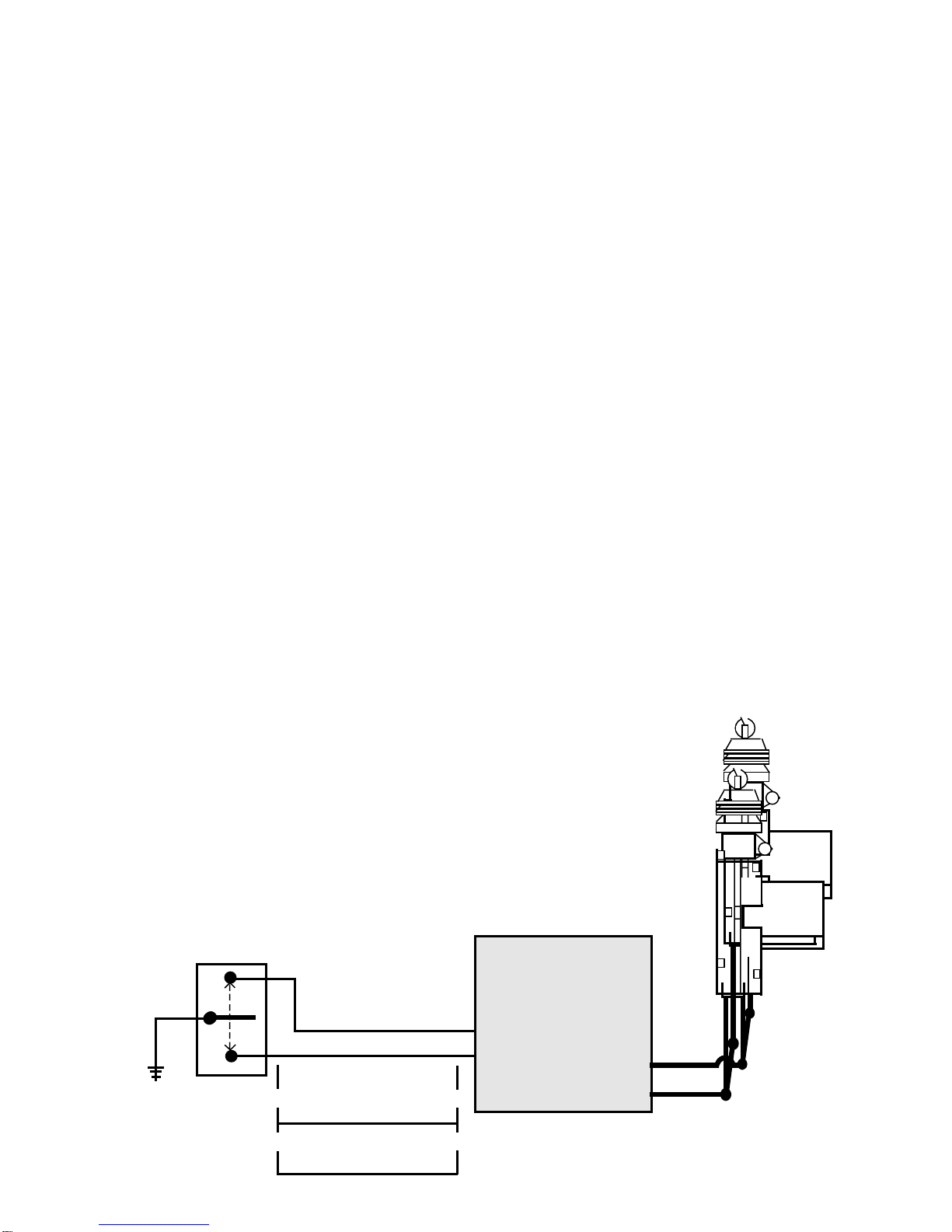
Orange Wire - (Output While Armed): All Models
StarterInterruptOptional On328i3,
Starter Interrupt Standard On 533i3& 745i3
The Orange wire is a Negative starter interrupt output, which is active
whenever the security system is in an armed state.
CONNECTION:Tointerruptthevehicle'sstartercircuit,thestarterwire
mustbelocated,identifiedandcut. Cuttingthevehicle'sstarterwirewillresult
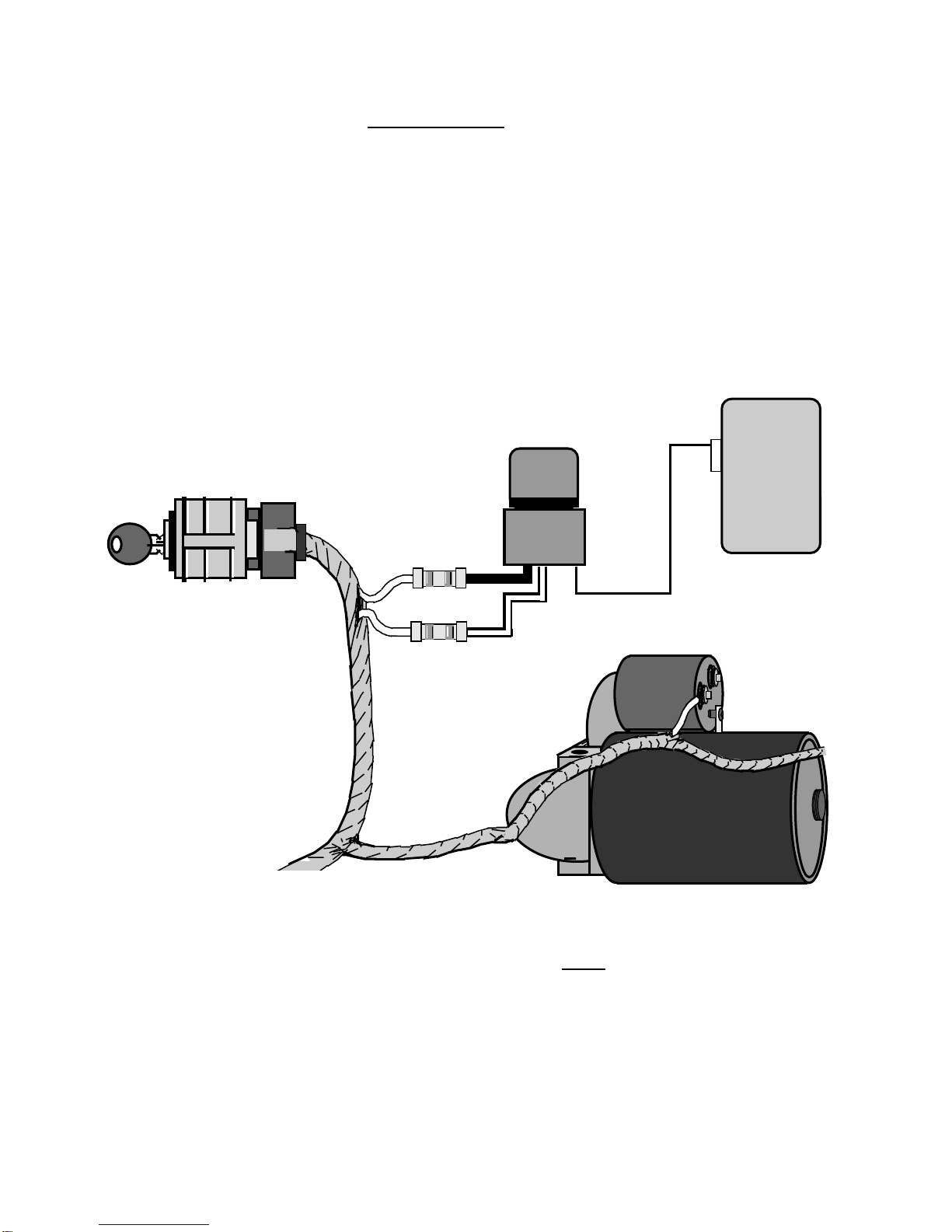
The starter wire will read Positive 12 Volts only when ignition key is in
"start" position (cranking the engine). Cut this wire at a suitable location.
Confirm that this is the correct wire by turning the ignition switch to the
"start" position. The starter should not engage Connect the starter disable
socket's Red wire to the ignition switch side. Connect the starter disable
socket’s White wire to the starter solenoid side. Be sure that good, solid
electrical connections are made as this generally is a high amperage circuit.
Page - 8
in two sides- the "ignition switch" side and the "starter solenoid" side. It is
recommendedthatthisconnectionbemadeasclosetotheignitionswitchas
possible. Use a voltmeter, not a test light, to find the correct wire, which is
the wire from the ignition switch to the starter solenoid.
CAUTION!Avoidtheairbagcircuit! Improperuseofatestlightcancause
deploymentoftheairbag,whichmayresultinbodilyinjury! Testlightscan
alsodamageon-boardcomputersandassociated sensors.
Typical Dash-Mounted Ignition Switch
Showing Starter Disable Connections
Dash-
mounted
Ignition
Switch
Relay
Starter Disable White
wire to the
Starter Solenoid
side of the cut
wire.
Starter
Solenoid
Starter
Motor
Starter Disable Red
wire to the Ignition
Switch side of the
cut wire. Starter
Disable
Socket
5-Pin
Connector
Socket
Orange
wire
Control
Module
Page - 9
Gray Wire - (Auxiliary Output #2): All Models
The Gray wire is an optional output; typically the primary use is for trunk
release. Unless the vehicle's existing trunk release switch draws no more
than 250mA, an optional relay must be used.
CONNECTION: Connect the Gray wire to relay pin (85), and connect
Constant Positive 12 Volts to relay pin (86). Connect pin 30 to power, or
ground, as needed. Pin #87 is then connected to the vehicle's trunk wire.
Please refer to the relay wiring instructions on the back cover.
Secondary Connections -
8-Pin Connector
Brown Wire - (Positive Siren Output): All Models
The Brown wire is a 1 Amp Positive output designed to operate the elec-
tronic siren for audible confirmations, and also to sound if the alarm is
triggered. An alternative to the siren is to program the alarm to pulse this
output to sound the vehicle's horn by adding an optional relay. This would
require changing Programmable Feature #22 from the preset “steady” out-
put to a “pulsed” output.
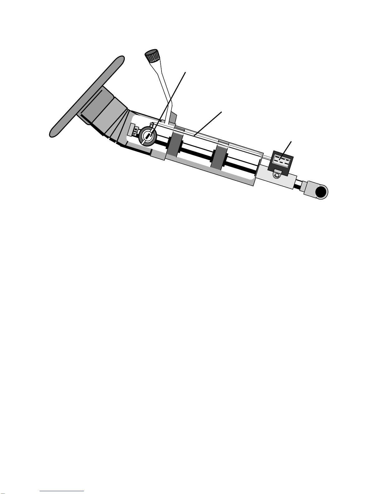
SIREN CONNECTION: The Brownwire may be connected directlyto
Cutaway View Of A Typical Steering
Column-Mounted Ignition Switch
Electrical part of the
Ignition Switch.
Linkage rod connecting
the two parts together.
Mechanical part of the ignition switch,
which is the ignition key cylinder.

Page - 10
the siren's Red wire, and the siren's Black wire is connected to (-) Ground.
SIRENMOUNTING: Find alocationin the enginecompartment away
fromtheextremeheatoftheengineandmanifold. Asuitablelocationwilloffer
a firm mounting surface, will also allow sound dispersion out of the engine
compartment, and not be accessible to a thief. The siren must be pointed
downwardtoavoidmoisturegettinginsideitandtoenhancesounddispersal.
Seepages4-5 formoresiren mountinginformation.
BLACK WIRE LOOP ON SIREN: Cut the short Black wire loop on
the siren for louder confirmation chirps.
HORN CONNECTION: The Brown wire may be used to sound the
vehicle's existing horn, but a relay must be used to switch the polarity to
Negative. Thehornswitchwireistypicallyfoundatthesteeringcolumn. Use
adigitalmultimeter(DMM)toidentifythehornwire. CAUTION! Avoidthe
Airbagcircuit! ThecorrectwirewillshowPositive12Voltsnormally,and
novoltagewhenthehornishonked. DirectconnectionoftheBrownwireto
the horn itself is not recommended because the average horn requires more
than the 1 amp output that the Brown wire supplies. One alternative is to
disconnect the horns, then operate the horn switch. A clicking sound from
the vehicle will confirm the presence of a horn relay. Another alternative is
to check a wiring schematic of the vehicle in question.
ConfiguringAnOptionalRelay: TheBrownSiren/Hornoutputwire
has a 1 Amp capacity, which, if exceeded, can damage the security system
controlmodule. Incertainsituations,amongthemmultipleoptionalsirensor
utilizingthevehicle'shorn,anoptionalSPDTrelayisrequired. Connectthe
Brownwire topin 86,ground pin85, connect pin 87 toNegative orPositive
12Voltsasneeded,andconnectpin30tothesoundgeneratingdevice’swire.
Optional Relay For Horn Wiring Diagram
30
86 87a 85
87
(-) Ground
To (+) or (-) as
needed to operate
the horn / sirens.
To vehicle's
horn wire.
Brown wire
from module.
Page - 11
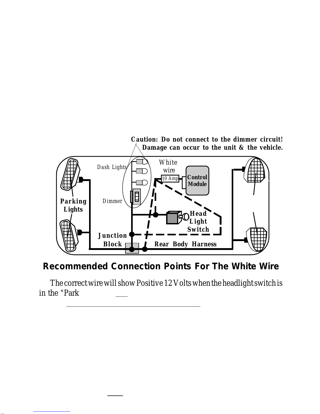
White Wire - (Flashing Light Output): All Models
This is a Positive 12 Volt output to flash the vehicle's parking lights for
visual arming confirmation, to illuminate them for disarming confirmation,
and to attract attention while the system is activated.
CONNECTION: Connect this wire to the vehicle's Positive 12 Volt
parking light circuit, which can usually be found at the following locations:
attheheadlightswitch,atthefuse/junctionblock,orintherearbodyharness
inthedriverkickpanel. Somevehicles,notablyToyota,haveaparkinglight
relay which is triggered by a Negative Ground circuit from the headlight
switch. The White wire can still be connected directly in these vehicles by
findingtheparkinglightcircuitaftertherelay,typicallyattheFuse/Junction
Block.
123456
123456
123456
123456
123456
123456
123456
123456
123456
123456
123456
12345
12345
12345
12345
12345
12345
12345
12345
12345
12345
123456
123456
123456
123456
123456
123456
123456
123456
123456
123456
123456
123456
123456
123456
123456
123456
123456
123456
123456
123456
123456
123456
123456
123456
123456
123456
1234
1
23
4
1
23
4
1
23
4
1
23
4
1
23
4
1
23
4
1
23
4
1
23
4
1
23
4
1
23
4
1234
123
1
2
3
123
Rear Body Harness
Head
Light
Switch
Junction
Block
Dash Lights
Dimmer
Control
Module
White
wire
10 Amp
Parking
Lights
Caution: Do not connect to the dimmer circuit!
Damage can occur to the unit & the vehicle.
Recommended Connection Points For The White Wire
ThecorrectwirewillshowPositive12Voltswhentheheadlightswitchis
in the "Parking Light" and "Head Light" positions. When such a wire is
located,alsotesttoensurethatitisnon-rheostated:whilemeteringthewire,
operatethedashlightdimmercontrol.Thecorrectwirewillshownochange
in voltage when the dimmer is operated. Do not connect the White wire to
arheostated(dimmer)circuit! Thiswillbackfeedtheparkinglightsthrough
therheostatorilluminationcontrolmodule,andpossiblycausedamagetothe
vehicle or security system control unit. Flashing the headlights is not
recommended. The halogen headlights found in modern vehicles are not
designed to be rapidly turned on and off, and if connected to the security
system,areductionoftheirusefullifemaybeoccur. Ifflashingtheheadlights
isstilldesired,arelaymustbeused,sincetheheadlight'scurrentdrawexceeds
Parking
Lights
Page - 12
the7ampratingofthebuilt-inrelay. Ifflashingheadlightsandparkinglights
aredesired, use two relays -configure onerelay to supply the parkinglights
and the other relay to supply the headlights.
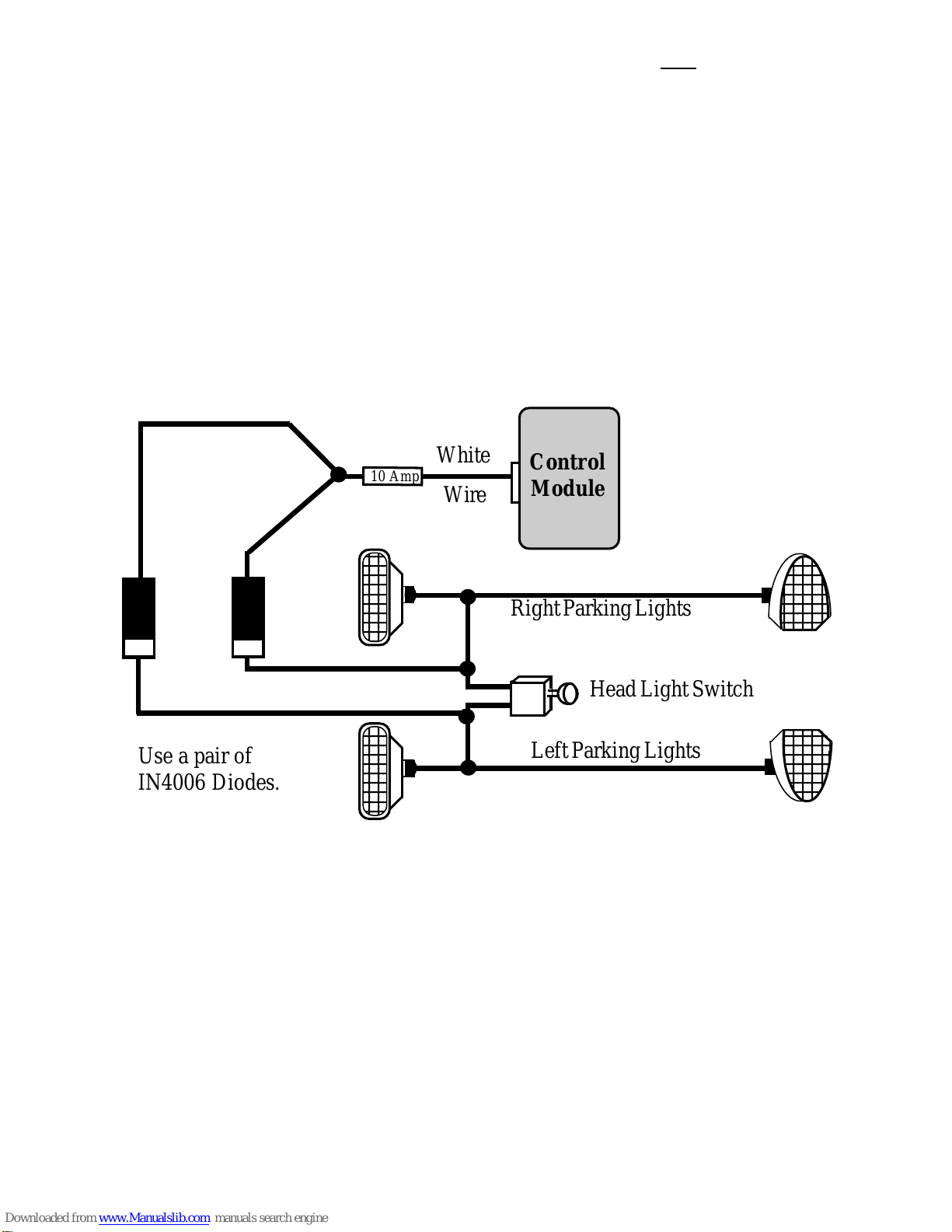
MULTIPLE PARKING LIGHT CONNECTIONS: Many European
imports have separate left and right side parking lights. When left & right
parking lights are on separate circuits, a pair of 6 to 10 amp diodes or a pair
ofSPDTrelaysmustbeusedtoconnecttheWhitewiretoeachparkinglight
side.
GreenWire-(NegativeDoorTrigger): AllModels
The Green wire is an "open door" input to the control module for vehicles
having Negative switching door pin switches.
The Green & Violet wires are Negative & Positive
door trigger inputs. Most typically, only one or the
other of these wires are needed. The Crime Guard
745i3also has “Smart Trigger”, which is covered in a
later section of this Installation Manual.
Connecting Separate Left And Right
Parking Lights Using Two Diodes
123456
123456
123456
123456
123456
123456
123456
123456
123456
123456
123456
123456
123456
123456
123456
123456
123456
123456
123456
123456
123456
123456
123456
123456
123456
123456
1234
1
23
4
1
23
4
1
23
4
1
23
4
1
23
4
1
23
4
1
23
4
1
23
4
1
23
4
1234
1234
1234
1234
1234
1234
1234
1234
1234
1234
1234
1234
1234
1234
1234
1234
1234
1234
1234
1234
1234
LeftParkingLights
Use a pair of
IN4006 Diodes.
HeadLightSwitch
10 Amp
RightParkingLights
Wire
White Control
Module
Page - 13
CONNECTION:ConnecttheGreenwiretoawireinthevehiclewhichis
commontoallofthedoorpin switches; thecorrectwireinthistypeofdome
light/doorjambpinswitchsystemwillhavenovoltagepresentandwillalso
show chassis ground when the doors are opened, and up to 12 volts when
the doors are closed.
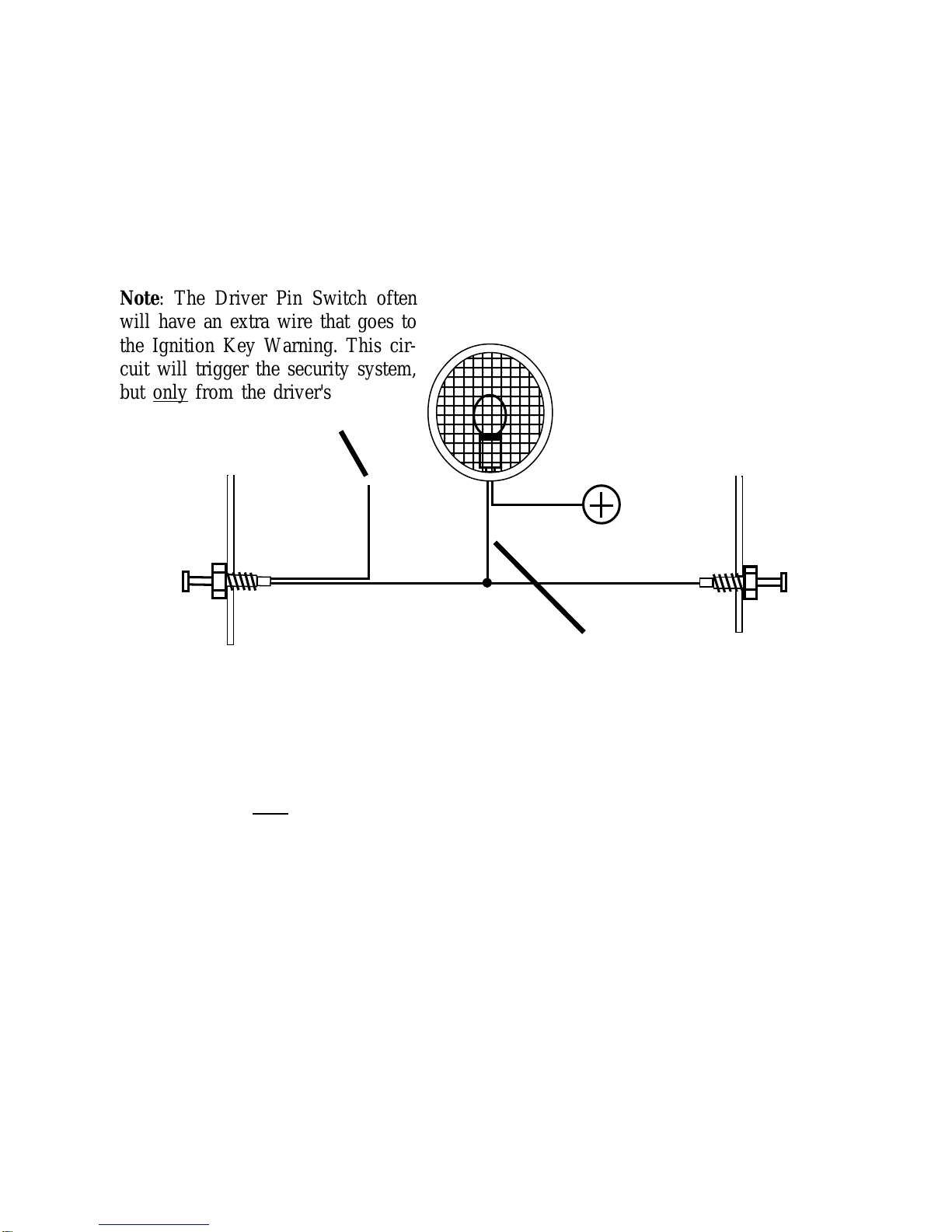
Notes, both types of dome light systems: The correct wire will show this
change when any of the doors are opened. If the vehicle has delay dome
lights, remember to take this into account when testing the wire. If the pin
switchismountedinthemetalstructureofthevehicle,andthedomelightgoes
out when the switch is removed, suspect a grounding-type dome light
system. While the traditional pin switch is mounted in the front door jamb
area, also be aware that many vehicles utilize other types of switch devices
tooperatetheinteriorlights.Someimportshaveaslidingtypeofswitchand
manyhavethepinorslidingswitchesinthereardoorjambarea.Inaddition,
some vehicles utilize switches in the doors, either connected to the exterior
door handles or to the latching mechanism. A vehicle which has the dome
lightsilluminatingwhentheexteriordoorhandleisliftedisanexampleofthis
typeofswitchingsystem. Alsobeawareofvehicleswhichdiode-isolateeach
door. Typically, this is usually encountered with dash displays that indicate
Passenger
Pin
Switch
This is the correct Activation
Wire. Connection may be
made at any point.
Typical Negative Switching Dome Light System
To 12 Volt
Constant
123456789012
123456789012
123456789012
123456789012
123456789012
123456789012
123456789012
123456789012
123456789012
123456789012
123456789012
123456789012
123456789012
123456789012
Note: The Driver Pin Switch often
will have an extra wire that goes to
the Ignition Key Warning. This cir-
cuit will trigger the security system,
but only from the driver's door; this
is the incorrect activation wire.
Dome
Light
12
12
12
12
12
12
12
12
12
12
12
12
12
12
12
12
12
12
12
12
12
12
12
12
12
12
12
1
1
12
12
12
12
12
Driver
Pin
Switch
Page - 14
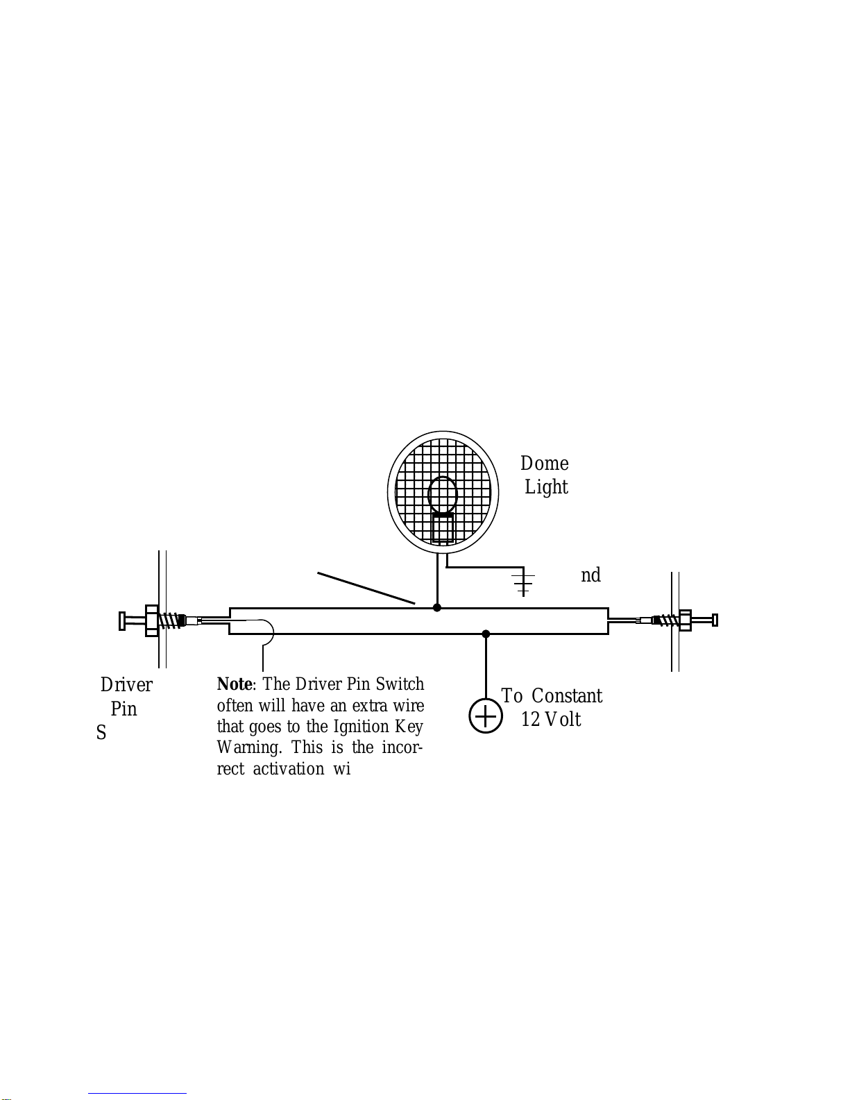
individual doors being ajar. The proper wire to connect to in this type of
system is the common wire which is routed to the dome light itself.
VioletWire-(PositiveDoorTrigger): AllModels
The Violet wire is identical to the Green Door Trigger wire, with the sole
exception that it is an open door input to the control module for vehicles
having Positive 12 volt door pin switches.
CONNECTION:ConnecttheVioletwiretoawireinthevehiclewhichis
common to all the door pin switches; the correct wire for this type of dome
light/doorjambpinswitchsystemwillhave12voltspresentwhenthedoors
are opened, and chassis ground when the doors are closed.
BlueWire-(NegativeInstantTrigger): AllModels
TheBluewireisaNegativeinstanttriggerusedprimarilytodetectentryinto
the hood or trunk area of a vehicle.
CONNECTION: Theincludedpinswitchesmaybeinstalledtoprovide
this trigger circuit; or, if there are existing switches (example: a light in the
luggagecompartmentora"TrunkAjar"lightinthedash),theBluewiremay
be connected directly, provided this is a negative ground switching circuit.
Anindicationofsuchacircuitisthewirehavingnovoltagepresentwhenthe
12
12
12
12
12
12
12
Driver
Pin
Switch
123456789012
123456789012
123456789012
123456789012
123456789012
123456789012
123456789012
123456789012
123456789012
123456789012
123456789012
123456789012
123456789012
123456789012
To Chassis
Ground
Dome
Light
To Constant
12 Volt
Note: The Driver Pin Switch
often will have an extra wire
that goes to the Ignition Key
Warning. This is the incor-
rect activation wire.
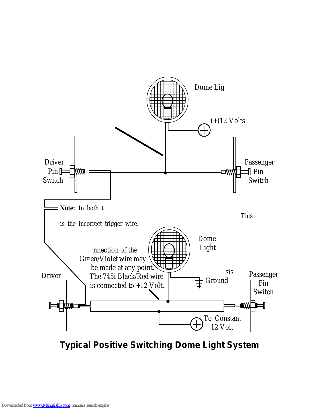
Typical Positive Switching Dome Light System
This is
the correct
Activation
Wire.
Passenger
Pin
Switch
Page - 15
hood or trunk is open, and up to 12 volts when the hood or trunk is closed.
This wire cannot be used with mercury switch types of hood or trunk lights.
Ifthevehicleisequippedwithausabletrunkorhoodcircuit,locatetheproper
wire and splice the Blue wire directly to the vehicle's wire.
When wiring more than one of the vehicle's circuits and/or additional
circuitstothiswire,diode-isolationmayberequiredtomaintaineachcircuit's
properoperation. An examplewould bewiring ahood pin switch and trunk
light switch together. Without isolating, the trunk light will turn illuminate
whenever the hood is raised. Also, diode-isolation is necessary when
combining electronic sensors together, or when adding a sensor in the same
circuit as the pin switches.
Pink Wire - (Auxiliary Output #3): 533i3& 745i3
The Pink wire is an optional output similar to the Gray trunk release wire;
however, this output is not capable of disarming the system when it is used
and therefore has no audible or visual confirmation.
CONNECTION: Formostapplicationsanoptionalrelaywillbeneeded;
connectthePinkwireto relaypin#85,andconnectConstantPositive12Volts
to relay pin #86. Connect pin #30 to power, or ground, as needed. Pin #87
istheoutput,andconnectedtothetargetwire. Pleaserefertotherelaywiring
instructions on the back cover.
Optional
Electronic
Sensor
Blue (-) Instant Trigger Wire.
Note: Use IN4002 Diodes,
which are available at most
electronics supply stores.
Trunk
Pin
Switch
Hood
Pin
Switch
Trunk
Light
Diode-Isolating Multiple Negative Instant Triggers
Control
Module

Page - 16
Black/Red & Green/Violet Wires - 745i3Only
(Domelight Supervision Input & Output)
The Crime Guard 745i3offers an additional safety and security feature-
“domelight supervision”. Upon disarming the 745i3, the interior lights will
flash, in conjunction with the parking lights. If desired, programmable fea-
ture #9 may be used to configure the parking and dome lights to flash, then
illuminate steady upon disarming. This allow the convenience of a lighted
approach to the vehicle and the safety of being able to inspect the vehicle’s
interior before entry.
The Green/Violet wire is the dome light supervision output, and the
Black/Red wire is used to select the Positive or Negative polarity which is
needed for the 745i3to operate the vehicle’s dome light.
Smart Trigger Feature: The 745i3’s dome light supervision
circuitcanbeconfiguredtoalsoserveasthe“dooropen”triggerinput. This
is the "Smart Trigger" feature which saves installation time while offering
enhanced integration flexibility. The Green/Violet Domelight Supervision
output wire has an additional function; it is also a door trigger input circuit,
serving the same purpose as either the Green or Violet door trigger wires.
CONNECTION GREEN/VIOLET: The proper vehicle wire to connect
theGreen/Violet wireto, thedome light activation wire, iscommon to all the
doorpinswitches. Thedomelightactivationwireisthesamewirethatthe
Green or Violet wire would be connected to, if either is used instead of
utilizing the Smart Trigger. The correct wire will change polarity as the
doors are opened and closed.
IfthevehicleusesaNegativeswitchingdomelightsystem,theactivation
wire will have no voltage present and show chassis ground when the doors
are opened, and up to 12 volts when the doors are closed. The correct wire
foraPositiveswitchingtypeofdomelight/doorjambpinswitchsystemwill
have 12 volts present when the doors are opened, and chassis ground when
the doors are closed. The correct wire will show these changes when any
of the doors are opened. If the vehicle has delay dome lights, remember to
take this into account when testing.
CONNECTIONBLACK/RED: Thepolarityofthedomelightsupervi-
sion output must be selected by the connection of the Black/Red wire as
PositiveorNegative. ConnectionoftheGreen/Violetshouldhavedetermined
which polarity the vehicle uses to operate the dome light; this is either
Page - 17
"Negative switching" or "Positive switching"; these diagrams show both
types. Once “Positive switching” or “Negative switching” has been deter-
mined,connecttheBlack/RedwiretoNegative(for“Negativeswitching”)or
Positive (for “Positive switching”) as needed.
Typically, “Negative switching” systems show voltage with
doors closed, and ground when the doors are opened; while
“Positive switching” systems show the reverse indications.
1
1
1
1
1
1
1
Driver
Pin
Switch
123456789012
123456789012
123456789012
123456789012
123456789012
123456789012
123456789012
123456789012
123456789012
123456789012
123456789012
123456789012
123456789012
123456789012
To Chassis
Ground
Dome
Light
To Constant
12 Volt
Passenger
Pin
Switch
Typical Positive Switching Dome Light System
1
1
1
1
1
1
12
12
12
12
12
12
1
1
1
1
1
1
12
12
12
12
12
12
1
1
12
12
12
12
Passenger
Pin
Switch
(+)12 Volts
Driver
Pin
Switch
Note: In both types the Driver Pin Switch will often have an extra
wire that activates the “ignition key in switch” warning chime. This
is the incorrect trigger wire.
1234567890123
1234567890123
1234567890123
1234567890123
1234567890123
1234567890123
1234567890123
1234567890123
1234567890123
1234567890123
1234567890123
1234567890123
1234567890123
1234567890123
Dome Light
Typical Negative Switching Dome Light System
This is the correct trigger
wire. Connection of the
Green/Violet wire may be
made at any point. The 745i
Black/Redwireisgrounded.
This is the correct trigger
wire. Connection of the
Green/Violetwiremay
be made at any point.
The 745i Black/Red wire
is connected to +12 Volt.

Page - 18
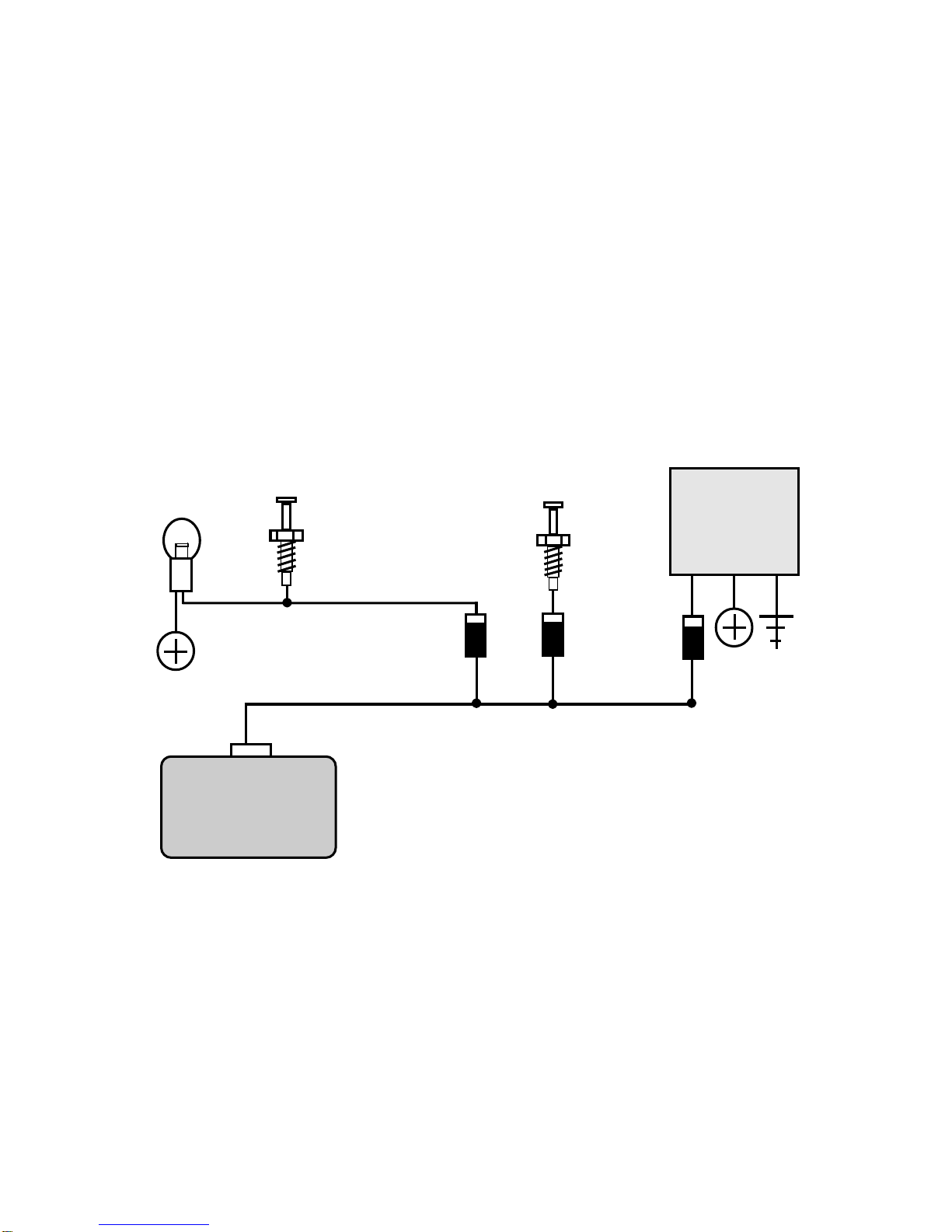
To Use Smart Trigger: After connection of the Green/Violet
and Black/Red wire is completed, all that is needed is to install the Smart
Triggerjumper inthe correctpolaritysetting. Tosetthe polarity,open the
access door on the 745i3’s case. Next to the White 2-pin port for the backup
battery is the Smart Trigger standup; refer to the below diagrams.
If the Black/Red wire was connected to Negative polarity, the Smart
Trigger jumper should be aligned to the left two pins (i.e.- inboard); if the
Black/Redwire wasconnected toPositive polarity,the SmartTriggerjumper
should be aligned right two pins (i.e.- outboard).
Setting “Positive Switching” Dome Light Smart Trigger
1234567890123
1234567890123
1234567890123
1234567890123
1234567890123
1234567890123
1234567890123
1234567890123
1234567890123
1234567890123
1234567890123
1234567890123
1234567890123
1234567890123
Green/Violet
10 Amp
Black/Red
DomeLightWire
Dome
Light
To Constant
12 Volt
Jumper
connects2rightpins
Control
Unit
2-PinBackup
Battery
Connector
“Negative Switching” Dome Light Smart Trigger
Ground
123456789012
123456789012
123456789012
123456789012
123456789012
123456789012
123456789012
123456789012
123456789012
123456789012
123456789012
123456789012
123456789012
Green/Violet
10 Amp
Black/Red
DomeLightWire
Dome
Light
Jumper
connects2leftpins 2-PinBackup
Battery
Connector
Control
Module

Page - 19
Not Using Smart Trigger: If the Smart Trigger feature is not
desired, connect the Green/Violet and Black/Red wires for the dome super-
vision operation, but do not install the polarity selecting jumper. If this is
done,either the GreenNegative door trigger wire orthe Violet Positive Door
Trigger wire must be connected in order for the control unit to detect an
open door.
Power Doorlock Interfaces
Although its primary purpose is the security of vehicle and contents, an
added benefit of a Crime Guard system is the convenience offered through
theremotecontroloperationoffunctionssuchaspowerdoorlocks. Allthree
CrimeGuardsystemsarecapable,withtheproperinterface,ofoperatingthe
vehicle'sexistingpowerdoorlocks. Evenifthevehicleisnotequippedwith
power doorlocks, it is still possible to add actuators to operate the manual
mechanicaldoorlocksviaremotecontrol.
Itisimportanttonotethatpowerdoorlockingsystemsvaryfromvehicle
to vehicle; therefore where one interface may be performed with parts
included with the Crime Guard system, another installation may require
optionalparts. Basically,therearetwoapproachestoperformingthepower
doorlock interface: the use of a “plug-in” Quick Interconnect Harness; or
“hardwiring” by direct wire-to-wire splicing between the security system
interfaceandthevehicle’swires. TheQuickInterconnectHarnessoffersthe
easiest, safest and most accurate method of interfacing a power doorlock
system. Otherwise, if hardwiring, a basic understanding of the vehicle’s
power doorlock system is most helpful.
Basic Types Of Power Doorlock Systems: The vast
majority of power doorlocks are found as only three different system types.
All other power doorlock systems which may be encountered, such as the
vacuum pump types found in older Mercedes vehicles and the single wire
types which have appeared in some late model vehicles, are actually varia-
tions or even combinations of the these three basic types:
3WireNegative
3Wire Positive
5WireReversal
Page - 20
3-Wire Negative Systems: In 3 Wire Negative systems, the
vehicle’sdoorlockswitchactivates“lock”and“unlock”relayspresentinthe
vehicle, which can be found separate, within a bank of relays, or sometimes
within a doorlock control unit. This power doorlock system is indicated by
thepresence of threewires at the switch. Typically, ofthe three wiresat the
switch:- One wire is constant Ground.
- One wire shows Ground when the switch is pushed to “lock”.
- One wire shows Ground when the switch is pushed to “unlock”.
With the switch at “rest” (not being operated), these two wires will read
voltage, usually 12 volt positive but in some cases less. The wires from the
switches operate doorlock relays or a doorlock control unit with built-in
relays; the correct connection point is
between the switches and the relays.
Thebestwaytoidentifyadoorlocksystemistoexaminethedoorlockswitch's
wiring. Thenames of thethreesystems areinfactderived fromthenumber
of wires, and their polarity, as found at the doorlock switch, although
variations can be encountered*.
*These“variations”includeilluminatedswitches,whichwillhavemorethan
thedescribednumberofwires,and“multipleswitchassemblies”whichhave
Powerand/orGround “bussed” internally,andtherefore appeartohaveless
than the described number of wires.
Diagram Of A Typical 3 Wire
NegativeDoorlockingSystem
Vehicle's Doorlock
Relay Control Unit
Doorlock
Switch
Unlock
Lock
Doorlock
Actuators
+
+
Ground “Lock” wire
“Unlock” wire
Interface performed
within in this area
Other manuals for 328i3
2
This manual suits for next models
2
Table of contents
Other Crime Guard Security System manuals


