Crison 44 User manual

CRI10032.99
MultiMeter 44
3 channel process multi-meter
User manual
Manual del usuario
12, 2017 Edition 2


1
Table of contents
Section 1 Specifications.................................................................................................................... 3
Section 2 General information.......................................................................................................... 7
2.1 Safety information......................................................................................................................... 7
2.2 Overview of product...................................................................................................................... 9
2.3 Instrument composition............................................................................................................... 10
Section 3 Installation......................................................................................................................... 13
3.1 Operating environment ............................................................................................................... 13
3.2 Wall mounting ............................................................................................................................. 13
3.3 Panel mounting........................................................................................................................... 15
3.4 Connections................................................................................................................................ 15
3.5 Installation verification................................................................................................................. 18
Section 4 Operation........................................................................................................................... 19
4.1 Startup ........................................................................................................................................ 19
4.2 Functioning. Keypad ................................................................................................................... 19
4.3 General diagram ......................................................................................................................... 20
4.4 Instrument configuration ............................................................................................................. 21
4.5 pH / mV channel ......................................................................................................................... 22
4.6 Conductivity channel (EC) .......................................................................................................... 27
4.7 DO channel (membrane sensor)................................................................................................. 31
4.8 D.O. Channel (optical sensor)..................................................................................................... 33
4.9 Chlorine channel (galvanic) ........................................................................................................ 36
4.10 Chlorine channel (amperometric).............................................................................................. 42
4.11 Cleaning relay........................................................................................................................... 48
4.12 Alarm relay................................................................................................................................ 48
4.13 Limit relays................................................................................................................................ 49
4.14 Analogical output ...................................................................................................................... 51
4.15 Data Logger .............................................................................................................................. 53
4.16 Temperature readjustment, °C or °F......................................................................................... 54
4.17 Recognized solutions................................................................................................................ 54
Section 5 Advanced operations ..................................................................................................... 57
5.1 RS 232 communication............................................................................................................... 57
5.2 RS 485 output............................................................................................................................. 61
5.3 PROFIBUS DP/V0 Output .......................................................................................................... 66
Section 6 Maintenance ..................................................................................................................... 71
6.1 Clean the measuring instrument................................................................................................. 71
6.2 Fuse replacement ....................................................................................................................... 71
6.3 Instrument power cord ................................................................................................................ 72
6.4 Disconnecting device.................................................................................................................. 72
Section 7 Troubleshooting............................................................................................................... 73
7.1 Error messages........................................................................................................................... 73
Section 8 Replacement parts and accessories........................................................................... 75
Section 9 Garantía limitada.............................................................................................................. 77
Appendix A Channel extension (addition)................................................................................... 79
A.1 Board installation....................................................................................................................... 79

2
Table of contents

3
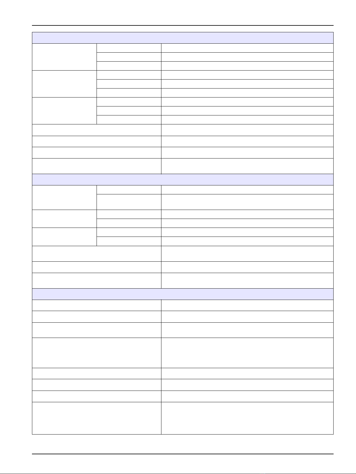
Section 1 Specifications
Specifications are subject to change without prior warning.
pH / mV measuring channel
Measuring Range
pH -2 to16 pH
mV ± 2000 mV
Temperature –20 to 150 ºC
Resolution
pH 0.01
mV 1
Temperature 0.1 ºC (0.18 ºF)
Measuring error
(± 1 digit)
pH ≤0.05
mV ≤3
Temperature ≤0.5 ºC (≤0.9 ºF)
Temperature
compensation
pH With Pt 1000 probe or manual introduction
mV Compensation is not carried out
Calibration
pH
1, 2 or 3 buffers to choose among pH 2.00, 4.01, 7.00, 9.21 and 10.90
at 25 ºC (77 ºF)
Acceptance criteria: asymmetry ± 58 mV, sensibility 70 to 105%
Indirect calibration at any pH value
Manual introduction of electrode calibration data
mV
In one point, 220 mV at 25 ºC (77 ºF)
Acceptance criteria: ± 60 mV respect to the theoretical value of the
standard at the calibration temperature
Indirect calibration or manual readjustment at any mV value
Manual introduction of electrode calibration data
Temperature readjustment Correction of the probe deviation
Relays 2 for limit. Switch N/O. Maximum load: AC < 250 V / < 3 A / < 750 VA.
Analogical outputs Two 4 to 20 mA outputs. One for pH or mV and the other for
temperature. R. maximum 500 Ohm
Channel for E. C. measurement (electrical conductivity)
Measuring interval
(resolution according
to measured range)
Conductivity 0.01* µS/cm to 1000** mS/cm (* with C = 0.1 cm-1 ** with C ≥9 cm-1)
Salinity 5.85 mg/L to 278 g/L NaCl
T.D.S. 0 mg/L to 200 g/L
Resistivity 5 Ohm×cm to 100 MOhm×cm
Temperature –20 to 150 ºC (–4 to 302 ºF)
Measuring error
(± 1 digit)
Conductivity ≤1% of measured value
Salinity ≤1% of measured value
T.D.S . ≤1% of measured value
Resistivity ≤1% of measured value
Temperature ≤0.4 ºC (≤0.72 º)
Temperature compensation Using Pt 1000 integrated probe in the cell or data entrance by keypad
Reference temperature, TR 20 or 25 ºC
Temperature coefficient, TC 0.00 to 5.00% / ºC

4
Specifications
Calibration
1, 2 or 3 standards to choose among: 147 µS/cm, 1413 µS/cm,
12.88 mS/cm and 80.4 mS/cm at 25 ºC (77 ºF)
Indirect (manual) calibration readjusting any value of conductivity,
salinity, TDS, resistivity or temperature
Manual introduction of the cell constant
TDS conversion factor Programmable between 0.40 to 1.00. Factory setting: 0.64
Relays 2 for limit. Switch N/O. Maximum load: AC < 250 V / < 3 A / < 750 VA
Analogical output Two 4 to 20 mA outputs. One for conductivity, salinity, TDS or
resistivity and the other for temperature. R. maximum 500 Ohms
DO measuring channel (membrane electrode)
Measuring Range
% 0 to 500
ppm 0 to 50
Temperature 0 to 50 ºC (32 to 122 ºF)
Resolution
%0.1
ppm 0.01
Temperature 0.1
Measuring error
(± 1 digit)
%≤0.1%
ppm ≤0.1%
Temperature ≤0.4 ºC (≤0.72 ºF)
Temperature compensation With NTC probe integrated inside the sensor
Salinity compensation Automatic with manual entrance by keypad
Pressure compensation Automatic with manual entrance by keypad
Calibration
In 1 point, in air, relative humidity 100%
Indirect calibration or manual readjustment at any DO value in % or
ppm
Relays 2 for limit. Switch N/O. Maximum load: AC < 250 V / < 3 A / < 750 VA
Analogical outputs Two 4 to 20 mA outputs. One for D.O. and the other for temperature.
R. maximum 500 Ohms
DO measuring channel (optical electrode)
Measuring Range
% 0 to 250
ppm 0 to 25
Temperature 0 to 60 ºC (32 to 140 ºF)
Resolution
%0.1
ppm 0.01
Temperature 0.1
Measuring error
(± 1 digit)
%≤0.1%
ppm ≤0.1%
Temperature ≤0.5 ºC (≤0.9 ºF)
Calibration
In 2 points, one of them 0.00 ppm
Indirect calibration or manual readjustment at any DO value in % or
ppm
Reset of calibration
Relays 2 for limit. Switch N/O. Maximum load: AC < 250 V / < 3 A / < 750 VA
Analogical outputs Two 4 to 20 mA outputs. One for D.O. and the other for temperature.
R. maximum 500 Ohms
5
Specifications
Free residual chlorine measuring channel (galvanic)
Measuring Range
mg/L (ppm) 0 to 5
mV ± 2000
Temperature 0 to 60 ºC (32 to 140 ºF)
Resolution
mg/L (ppm) 0.01
mV 1
Temperature 0.1
Measuring error
(± 1 digit)
mg/L (ppm) ≤1%
mV ≤2
Temperature ≤0.4 ºC (≤0.72 ºF)
Temperature compensation With Pt 1000 sensor integrated in the probe
Calibration Indirect or manual calibration readjusting any value of free chlorine
Relays 2 for limit. Switch N/O. Maximum load: AC < 250 V / < 3 A / < 750 VA
Analogical outputs Two 4 to 20 mA outputs. One for chlorine and the other for
temperature. R. maximum 500 Ohms
Free residual chlorine measuring channel (membrane)
Measuring Range
mg/L (ppm) 0 to 20
Temperature 5 to 45 ºC (41 to 113 ºF) (Only if a temperature probe Pt1000 is
connected)
Resolution mg/L (ppm) 0.01
Temperature 0.1 (Only if a temperature probe Pt1000 is connected)
Measuring error
(± 1 digit)
mg/L (ppm) ≤1%
Temperature ≤0.4 ºC (≤0.72 ºF) (Only if a temperature probe Pt1000 is connected)
Calibration Calibration against a reference value obtained by DPD-1, readjusting
at any chlorine value in the measuring range
Relays 2 for limit. Switch N/O. Maximum load: AC < 250 V / < 3 A / < 750 VA
Analogical outputs Two 4 to 20 mA outputs. One for chlorine and the other for
temperature. R. maximum 500 Ohms
Common specifications for all channels
Control mode ON/OFF and Proportional
Data Logger Storage of 2000 data
Relays 1 sensors cleaning (N/O) and 1 alarm (N/C). Maximum load: CA < 250
V / < 3 A / < 750 VA
4-20 mA output
230 V and 115 V instruments: 4-20 mA signal is galvanically isolated
from mains ground.
24 V instrument: 4-20 mA signal is not galvanically isolated from
mains ground.
Communication RS 232 C (Optionally RS 485 and PROFIBUS)
Display Graphic, LCD, backlit, 128 x 64 dots.
Keypad Membrane, 7 keys. Material PET with protective treatment.
Power supply
230 V AC ±10 %, 45-65 Hz 10 VA (standard version)
24 V AC/DC ±10 %, 45-65 Hz 10 VA (standard version)
115 V AC ±10 %, 45-65 Hz 10 VA (under demand)
Overvoltage category: II.
6
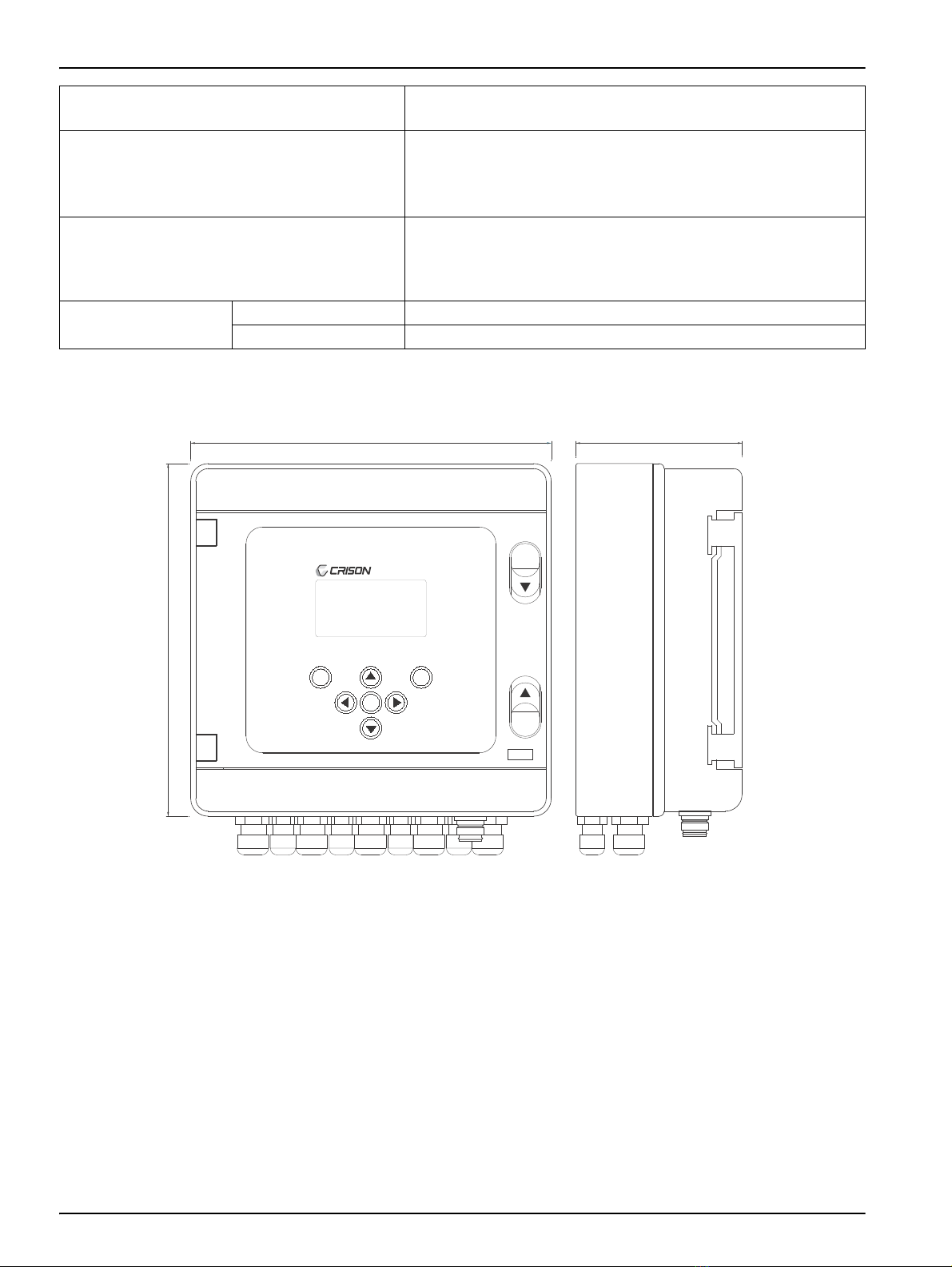
Specifications
Figure 1 Instrument dimensions
EC Directives Electrical security according to 2006/95/EC
Electromagnetic compatibility according to 2004/108/EC.
Environmental conditions
Working temperature: 0 to 50 ºC (32 to 122 ºF)
Storage temperature: -20 to 65 ºC (-4 to 149 ºF)
Relative humidity < 80 % (non condensing)
Altitude requirements: max. 2000 m (6562 ft) ASL (Above Sea Level)
Enclosure
Protection IP 65 (With rear cover installed, transparent door closed
and connector MP-5 protected.)
Inflammability rate, Glow wire test 650ºC, UL 94 HB.
Material free of halogens
Physical parameters Weight 1800 g
Dimensions 210 x 215 x 100 mm. (see Figure 1)
MultiMeter 44
ESC
OK
*
IP 65
215
210
100
7
Section 2 General information
As a result of constant improvements to our products sometimes differences may exist
between this manual and the instructions supplied with the instrument.
2.1 Safety information
Please, read carefully this information before installing and using the instrument!
Pay attention to all danger and caution statements.
Follow all instructions and recommendations in this manual. Otherwise the protection
provided in the instrument may be compromised and damaged. If the instrument is used in
a manner not specified by the manufacturer, the protection provided by the instrument
may be impaired.
2.1.1 Use of hazard information
Note: Information that supplements points in the main text.
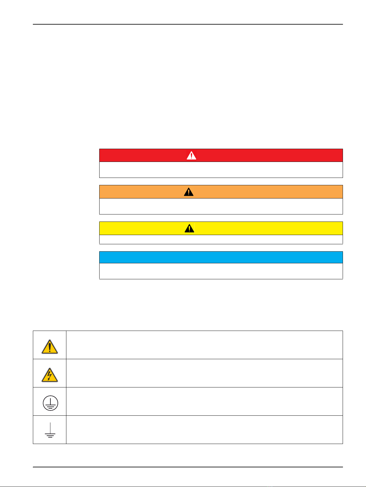
2.1.2 Warning labels
Read carefully all labels and tags attached to the instrument.
DANGER
Indicates a potentially or imminently hazardous situation that, if not avoided, results in death or
serious injury.
WARNING
Indicates a potentially or imminently hazardous situation that, if not avoided, could result in death
or serious injury.
CAUTION
Indicates a potentially hazardous situation that may result in minor or moderate injury.
NOTICE
Indicates a situation that, if not avoided, could result in damage to the instrument. Information that
requires special emphasis.
This symbol, if noted on the instrument, references the instruction manual for operation and/or safety
information
This symbol may be found on an enclosure or barrier within the product and indicates a risk of electrical shock
and/or death by electrocution
This symbol indicates the connection for Protective Earth
This symbol indicates the connection for ground
8
General information
2.1.3 Safety information for the correct use of the instrument
•Remember that the voltage across accessible parts of the open instrument, may be
dangerous to life. Do not open the instrument when it is connected to the power
supply, there are areas whose voltage could cause death.
•Always disconnect power to the instrument before it is opened.
•Repair or adjustment of an opened instrument under voltage shall be carried out only
by a qualified technician who is aware of the hazards involved.
•Never work in an environment subject to explosion hazards. The housing of the
instrument is not gas tight.
•The Company will not be responsible for any physical damage caused by non
authorised work or manipulation.
•It is the responsibility of whoever uses this instrument to consult and establish
appropriate safety and health practices and determine the applicability of regulatory
limitations prior to use.
•Before connecting the instrument to a power supply unit, make sure that the mains
voltage lies within the range:
•230 V AC ±10 %, 45-65 Hz (standard version).
•24 V AC/DC ±10 %, 45-65 Hz (standard version).
•115 V AC ±10 %, 45-65 Hz (under demand).
Important notes:
•Read carefully the manual of the instrument.
•Avoid direct sunlight over the instrument.
•Exclude the following environmental influences:
•vibrations
•atmospheric humidity higher than 80 %
•corrosive gases present
•temperature < 0 °C, or > 50 °C (< 32 °F, or > 122 °F)
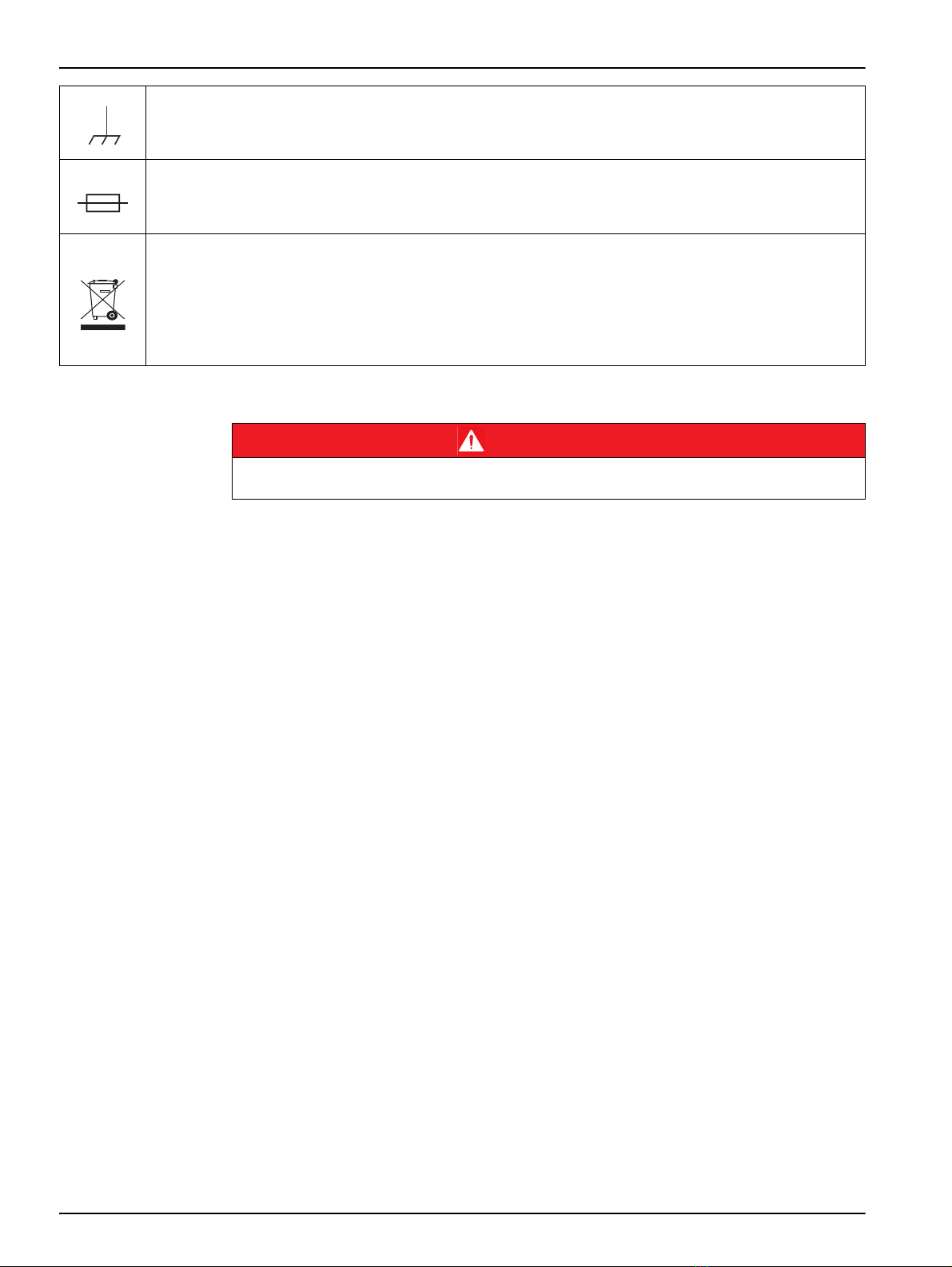
This symbol indicates the connection for analogic ground
This symbol identifies a fuse
Electrical equipment marked with this symbol may not be disposed of in European public disposal systems
after 12 August of 2005. In conformity with European local and national regulations (EU Directive 2002/96/EC),
European electrical equipment users must now return old or end-of life equipment to the Producer for disposal
at no charge to the user.
Note: For return for recycling, please contact the equipment producer or supplier for instructions on how to
return end-of-life equipment, producer-supplied electrical accessories, and all auxiliary items for proper
disposal.
DANGER
Multiple hazards. Follow the following safety information, in addition to any local guidelines in
force.
9
General information
•powerful electric and magnetic fields.
•Only use original accessories and spare parts.
•Have the instrument serviced only by the Company Service.
2.2 Overview of product
The MULTIMETER 44 it’s a multi-meter for pH, EC, DO and Chlorine measure. It can
measure and display up to three different parameters. The instrument is able to send the
information to other instruments and also able to indicate, through relays or 4-20 mA
outputs, if the measures are inside or outside of certain limits.
The MULTIMETER 44 has a plastic enclosure highly resistant to impact, dust and water,
protection IP 65. It can be used to work outdoor and in any type of industry.
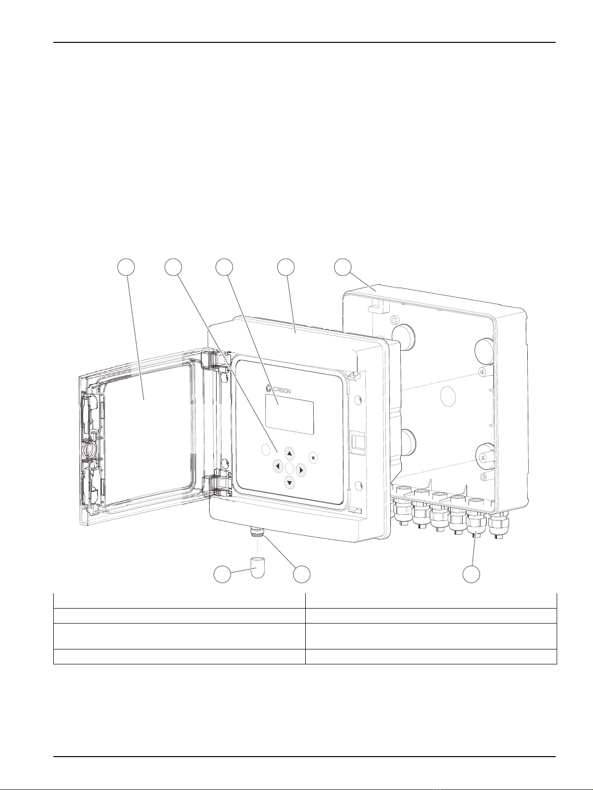
Figure 2 Instrument parts
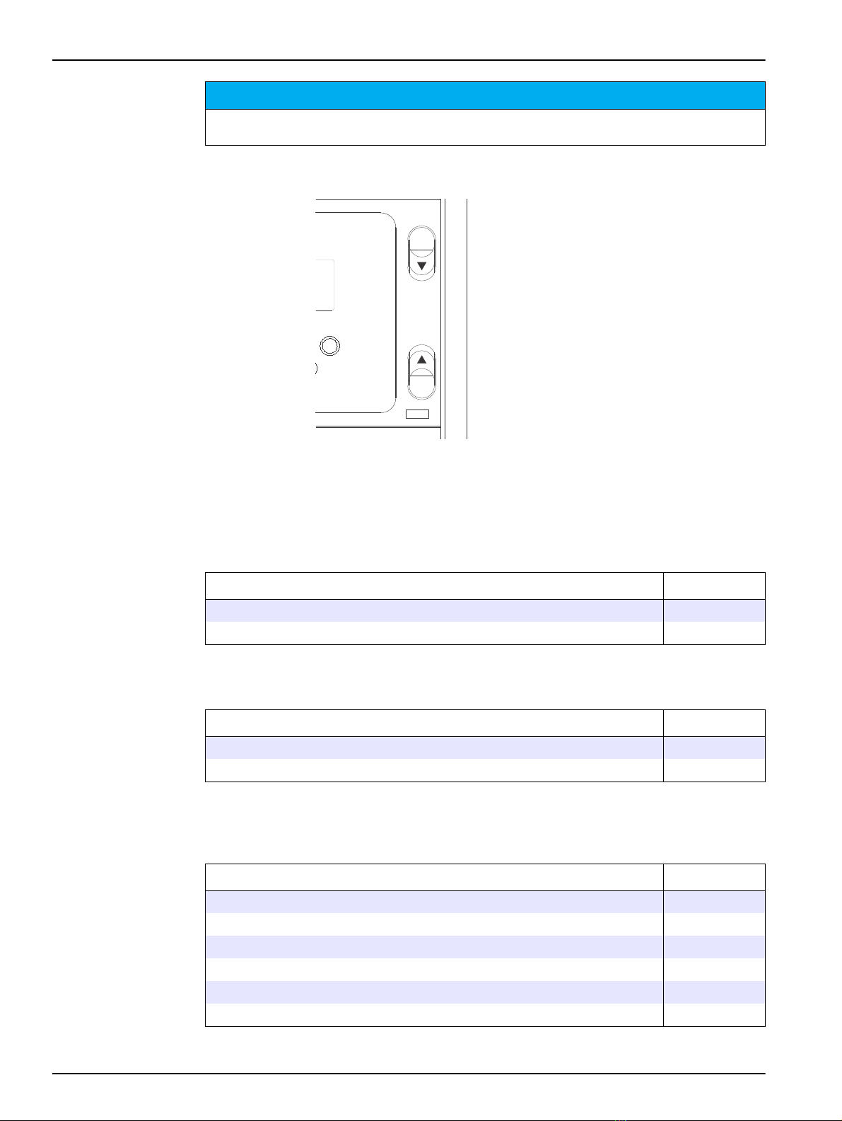
2.2.1 Open the instrument door
Press as the arrows indicate to open the transparent frontal door, see Figure 3, Page 10.
1Transparent door 5Rear cover
2Membrane keypad 6Cable glands
3Graphic display 7MP-5 connector. Direct connection with RS 232 output
for data loading from the Data Logger.
4Frontal. Remove for cable connection 8Protector cup for MP-5 connector
ESC
OK
MultiMeter 44
5
68 7
41 2 3
10
General information
Figure 3 Door detail
2.3 Instrument composition
The MULTIMETER 44 is a modular instrument that can be configured with 1, 2 or 3
channels. The instrument can be delivered complete with 3 channels or the number of
channels can be extended as needed.
* To be completed with 1, 2 or 3 measuring boards
NOTICE
The instrument protection IP 65 is only ensured with the door closed and connector MP-5
protected. For Panel Mounting instruments, see 3.3 Panel mounting, page 15
*
IP 65
2.3.1 Base module
Description Code
MultiMeter 44, base instrument*, 220 V. 44 00
MultiMeter 44, base instrument*, 24 V 44 01
2.3.2 Additional communication
Description Code
RS 485 interface installed on MultiMeter 44 ...485
PROFIBUS DP output installed on 44 ...pro
2.3.3 Measuring boards
See instrument and measuring boards specifications in the corresponding chapter of the
manual.
Description Code
Measuring board: pH/mV + Temperature 44 10
Measuring board: Conductivity + Temperature 44 20
Measuring board: D.O. (membrane) + Temperature 44 30
Measuring board: D.O. (optical) + Temperature 44 40
Measuring board: Chlorine (galvanic) + Temperature 44 50
Measuring board: Chlorine (membrane) + Temperature 44 60

11
General information
* The measuring board can be used for temperature regulation too (ºC or ºF). Also two ferrite clamp
are included, see 4.5 pH / mV channel, page 22.
2.3.4 Accessories
Description Code
GSM module for data sending to mobile phone. Includes cable for
MultiMeter 44 connection 44 96
Memory module for Data Logger empty or capacity extension. Includes
union cable to MultiMeter 44 and USB to PC 44 97
RS 485 / USB convertor module. Includes cables and PC software 44 98
RS 232 / USB convertor module. Includes cables and PC software 44 99

12
General information

13
Section 3 Installation
3.1 Operating environment
•A minimum clearance of 5 cm (2 in.) must be ensured above and on all sides of the
device. This allows the air to circulate and prevents overheating of the electric parts. In
the lower part left a minimum clearance of 15 cm (6 in.) of space underneath must be
ensured for the cable connections.
•Don’t install the instrument directly exposed to the sun or rain to avoid possible
damage to it. When installing outdoor, place the instrument always under a small roof
protected from direct sun or rain. If not programming the instrument, left always the
front door closed.
•When positioning the instrument and the disconnecting device, It has to be guarantee
that it’s easy the access to operate the disconnecting device.
3.2 Wall mounting
1. Completely open the transparent door and pull to remove it.
Note: Make sure that you do not misplace the black hinges of the transparent door.
2. Unscrew the four screws of the frontal cover.
3. Remove the back cover and the four cover-screw caps.
4. Four drill holes are required as indicated in Figure 4.
5. Once the rear cover is fixed on the wall by the four screws, the cover-screw caps
must be put to ensure the waterproof IP 65.
6. Assemble the housing and screw the four screws.
7. Mount the transparent door.
DANGER
Only qualified personnel should conduct the installation tasks described in this section of the
manual.
Do not replace any component unless power has been switched off or the area is known to be
non-hazardous.
Install the instrument in ambient protected by corrosive fluids.
Safety of any system incorporating this instrument is responsibility of the assembler of the
system.

14
Installation
Figure 4 Wall mounting
1Completely open the transparent door and pull to
remove it 4Four drill holes are required as indicated in Fig. 6
5Fix the rear cover. Put the cover-screw cups
2Unscrew the four screws of the frontal cover 6Assemble the housing and screw the four screws
3Remove the back cover and the four cover-screw caps 7Mount the transparent door
1
3
5 6 7
4
2
1
180°
2
115 mm
[4.52t in]
110 mm
[4.33 in]

15
Installation
3.3 Panel mounting
Four adaptors for panel mounting are supplied with the instrument MULTIMETER 44. Panel
instruments are installed without the rear cover.
1. Completely open the transparent door and pull to remove it, see Figure 4.
Note: Make sure that you do not misplace the black hinges of the transparent door.
2. Unscrew the four screws for the extraction of the frontal part of the instrument, see
Figure 4.
3. A hole as indicated in figure 10 is required in the panel.
4. Use the four adaptors to screw the instrument in the panel.
5. Mount the transparent door.
Figure 5 Panel mounting
3.4 Connections
3.4.1 Safety information
When making any wiring connections to the instrument, any warnings and notes found
throughout the manual must be adhered to. For more safety information refer to
section 2.1, page 7.
DANGER
The voltage across accessible parts of the instrument may be dangerous to life.
The IP 65 protection only applies to the front part of the instrument (with door closed and MP-5
connector covered). In panel mounting installation the overall IP protection of the instrument will
depend on the panel and instrument installation.
1Measurements to punch the panel where the instrument
will be installed 34 screws of the frontal cover, see Figure 4
2Adapters for panel mounting 4Instrument mounted
202 mm
R5 mm
[7.95 in]
206 mm
[8.11 in]
2 3
1
4
16
Installation
3.4.2 Electrostatic Discharge (ESD) Considerations
Some internal electronic components can be damaged by static electricity, resulting in
degraded instrument performance or eventual failure.
The manufacturer recommends taking the following steps to prevent ESD damage to the
instrument:
•Before touching any instrument electronic components (such as printed circuit cards
and the components on them) discharge static electricity from your body. This can be
accomplished by touching an earth-grounded metal surface such as the chassis of an
instrument, or a metal conduit or pipe.
•To reduce static build-up, avoid excessive movement. Transport static-sensitive
components in anti-static containers or packaging.
•To discharge static electricity from your body and keep it discharged, wear a wrist
strap connected by a wire to earth ground.
•Handle all static-sensitive components in a static-safe area. If possible, use anti-static
floor pads and work bench pads.
3.4.3 Electrical installation
High-voltage wiring for the instrument is protected by a protective casing. The protective
casing must remain in place unless a qualified installation technician is installing wiring for
power.
Always disconnect power to the instrument when making any electrical connections.
3.4.3.1 Protective earth
MULTIMETER 44 requires protective earth connection. Connect to terminal 8 a ground wire
of the electrical system.
3.4.3.2 Instrument power cord
The cable must be in accordance with IEC 60 227 or IEC 60 245 and designed to
withstand at least a current of 0.5 A with a voltage of 265 V.
3.4.4 Sensors connection
Follow the steps 1 to 3 on Figure 4 Wall mounting, page 14 to remove the frontal cover
and access to the interior view for the instrument connections.
See additional information in the sections of the corresponding channels.
DANGER
Always disconnect power to the instrument when making any electrical connections
NOTICE
The electrical installation where you connect the instrument should have an automatic switch
circuit breaker which must fulfill:
1It must be in the immediate proximity of the instrument and must easily be accessible for the
operator.
2It must be marked like device of disconnection of the instrument.
17
Installation
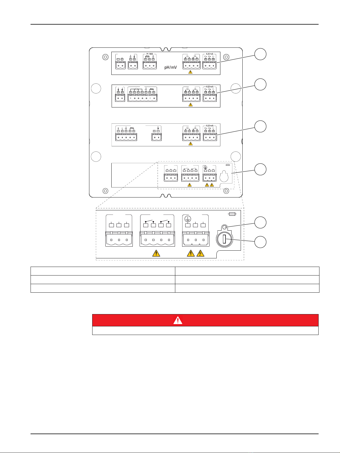
Figure 6 Interior view. Terminal assignment
3.4.5 Protecting wiring of switching contacts
The relays contacts are subjected to electrical erosion. Especially the inductive and
capacitive loads reduce the service life of the contacts. To eliminate sparks and arcing,
components such as combinations of resistances and capacitors (RC), non-linear
resistors, series resistors and diodes are used.
1Channel 1 4Power supply, relays and communication
2Channel 2 5Indicator for fused fuse
3Channel 3 6Fuse
Ground
Relays
E.C.
(Conductivity)
RelayspH/mV Electrode
Signal
Cell
D.O.
(Membrane)
RS 232 Relays
NL
Mains
Fuse
110/230V: T100L 250V
24V: T500L 250V
8910
GND
TxD
RxD
Alarm Cleaning
123 4567
Relays
DO Sensor (M)
RS 232 Relays
NL
Mains
Fuse
110/230V: T100L 250V
24V: T500L 250V
8910
GND
TxD
RxD
Alarm Cleaning
123 4567
1
2
3
4
5
6
DANGER
Limit the current up to 3A by using one fuse. Do not connect cables with voltage higher than 24 V
18
Installation
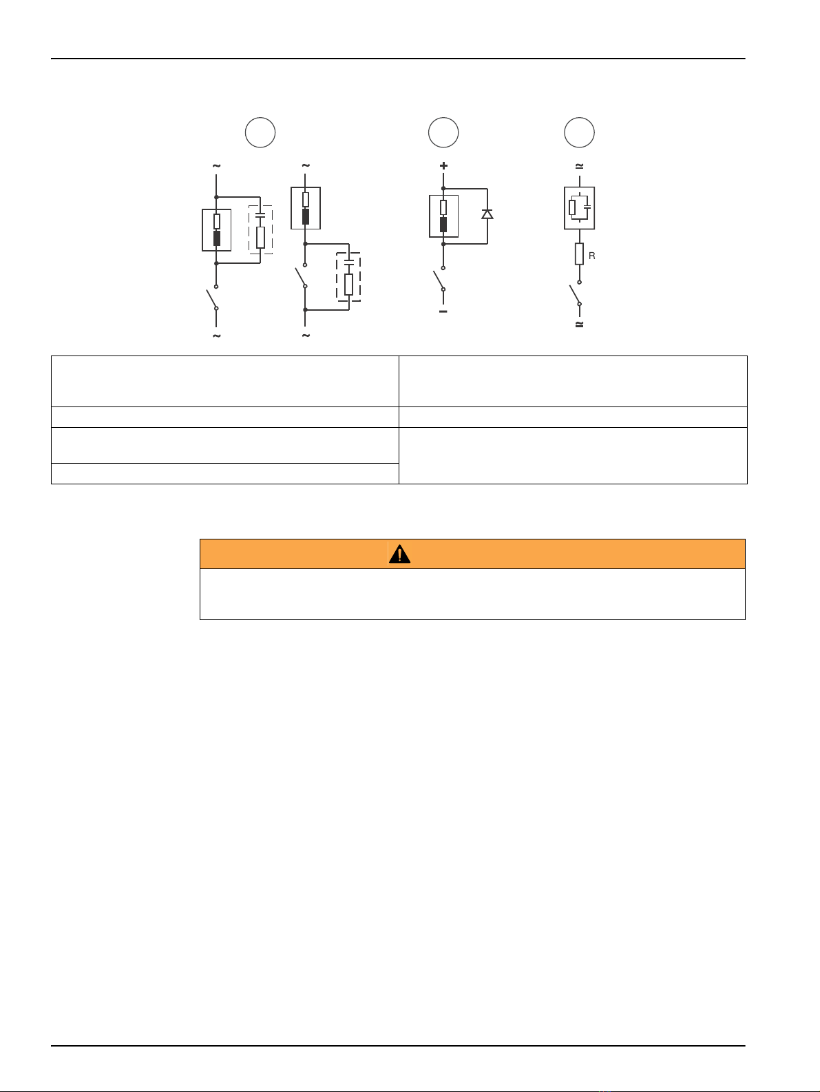
Figure 7 Typical protective wirings
3.5 Installation verification
Important notes:
•During the installation checking the limit relays and alarm relay stay deactivated.
•When a GSM sending is configured, it can be verified as well.
•The optional outputs, 485 and PROFIBUS, can be checked from this option too.
•The External Hold can be checked too.
1. From the measurement display press ESC.
2. Introduce the code 100 and accept with OK.
3. Go to SYSTEM and then CHECK INSTALLATION
4. Select RELAYS or 4-20 MA OUTPUTS to verify.
•Relays: Pressing OK the selected relay is activated. When the OK key is released the
relay is deactivated. The alarm relay acts in opposite manner.
•4-20 mA output: Select on display the mA value wanted to be simulated.
1In AC and inductive load
Typical RC at 230 VCA: Capacitor 0.1 µF/630 V;
Resistor 100 Ohms/1 W
5Load
2In DC and inductive load 6RC (resistance and capacitors)
3In AC/DC and capacitive load
(R example: 5 Ohms/ 1 W at 24 V/0.4 A) 7Diode: 1N4007
4Relay contact
1 2 3
4
5
5
6
6
7
55
44
4
WARNING
Relays or 4-20 mA outputs may be connected to control valves or pumps. Before using the relays
or 4-20 mA test options, be sure that those activations cannot produce any damage to people or
an environmental impact.
Table of contents
Languages:


