Critec SES65 120/240 User manual
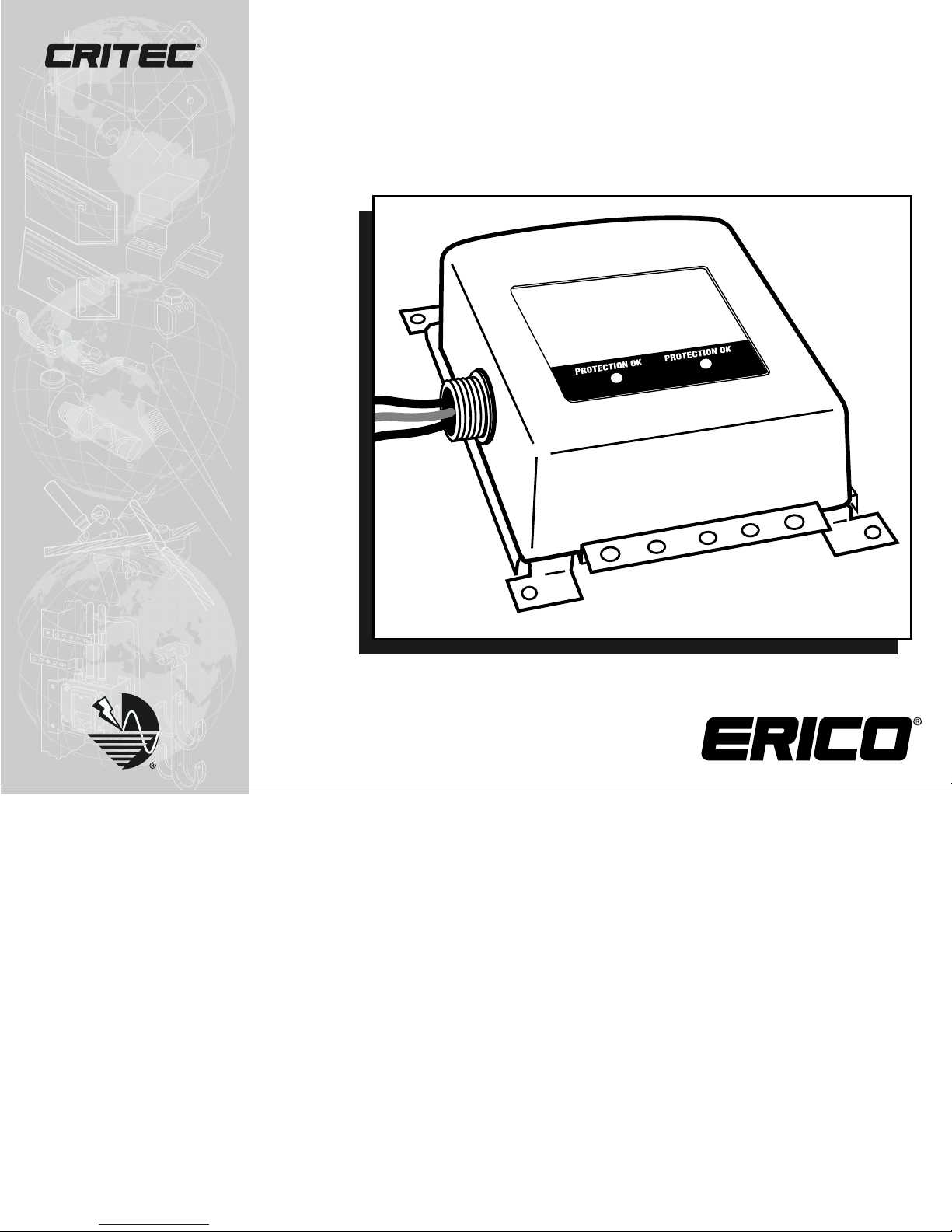
SES65 120/240
AC Panel Protector
Indoor/Outdoor Installation
& Operating Instructions
2
INDOOR/OUTDOOR INSTALLATION & OPERATING INSTRUCTIONS
SES65 120/240 AC Panel Protector
Phone: 800-248-9353
www.erico.com
SES65 120/240 AC PANEL PROTECTOR
DESCRIPTION
AC surge protector permanently connected to main service panel.
The SES65 120/240 features a compact chassis, visible and audi-
ble diagnostics, easy installation and a five-year warranty (see
back page).
Designed for 120/240 V, 1 Phase, 2 wire plus ground
and 120/240V, 1
Phase, 3 wires plus ground applications.
APPLICATION
The unit protects against electrical surges that can cause damage
to electric and electronic equipment. Catastrophic failures and
gradual component degradation can be caused by high voltage
surges, which are generated by harsh weather conditions, external
power anomalies, or day-to-day electrical component switching.
The SES65 120/240 will protect electrical equipment against
surges caused by the above factors. However, for effective equip-
ment protection, we recommend using secondary protectors at
the location of the equipment you would like to protect.
SAFETY CONSIDERATIONS
A certified electrician must install the protector. Installation
must follow applicable electrical codes. Failure to follow instal-
lation instructions may result in personal injury, equipment
damage and invalidation of the warranty.
Your electrical system must be grounded per Article 250 of the
NEC. Surge protection works best when a secure ground is
established. Check grounding before restoring power.
!
CAUTION:
When installing or removing this protector from service, disconnect power.
Failure to do so may result in equipment damage, serious injury or death.
!
SERVICE PANEL
SURGE
PROTECTOR
CONDUIT
Figure 1
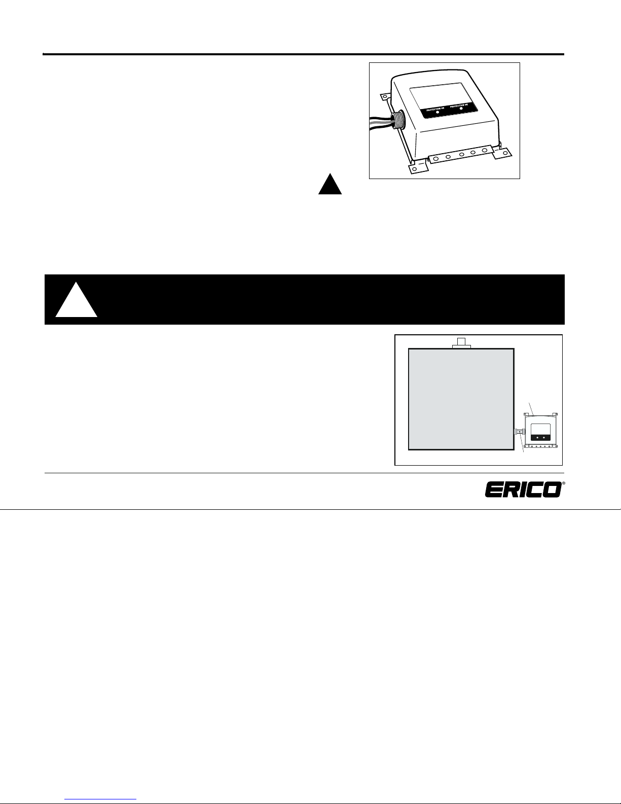
MOUNTING INSTRUCTIONS
Install unit according to local electrical codes, or using instructions below. Lead
lengths must be as short as possible to keep voltage drop to a minimum. Trim
excessive length to provide for lowest wire impedance to the surge protector. In
the event of lightning or other power transients, a one-foot reduction of
connecting lead length can reduce the let-through voltage reaching downstream
equipment by 100 volts or more.
Use a threaded nipple or thin-wall conduit to connect the unit to the service panel.
Feed the wires through into the conduit and into the panel.
Using the screw holes on the back plate corners, mount unit as close as possible
to the service panel (Figure 1).
3
Phone: 800-248-9353
www.erico.com
INDOOR/OUTDOOR INSTALLATION & OPERATING INSTRUCTIONS
SES65 120/240 AC Panel Protector
HOT
NEUTRAL
HOT
GROUND
BLACK GREEN
BUILDING
GROUND
120V
240V
120V
USE BUS TO CONNECT GROUND
WIRES FOR TELCO OR COAX LINES
METER
30 A BREAKER OR
SUB-FEED LUG SET
B
B
B
MAIN
DISCONNECT
FROM SES65 120/240
GROUND BUS
30 A BREAKER
OR SUB-FEED
Figure 2
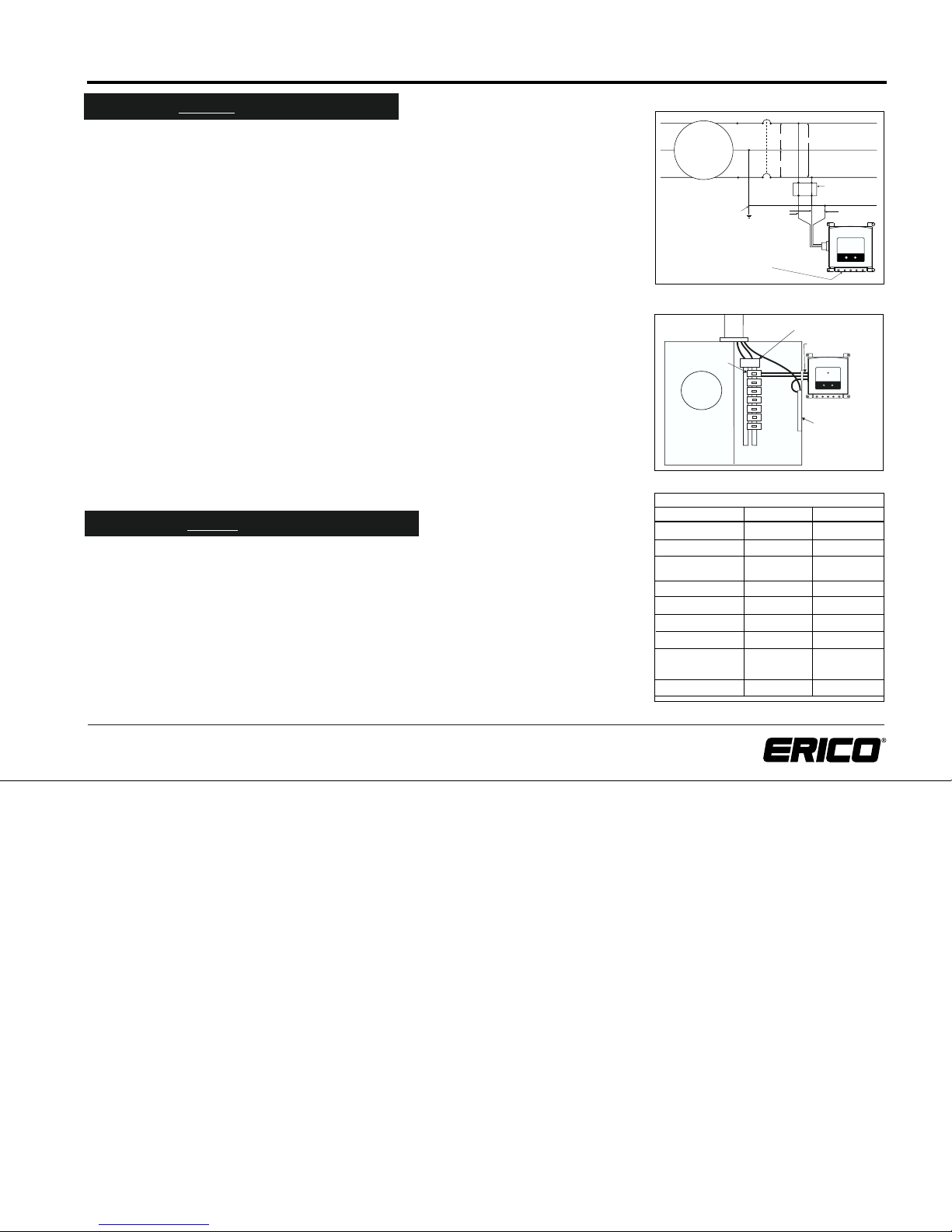
Figure 3
Installation BEFORE The Main Disconnect
WARNING: REMOVE THE METER OR OTHERWISE DISCONNECT THE AC POWER BEFORE
BEGINNING THE INSTALLATION!!!
The SES65 120/240 should be installed by qualified and authorized personnel.
USE A TEST LAMP TO CONFIRM THAT THE POWER HAS BEEN REMOVED!!
The SES65 120/240 protector is UL Listed for installation either before or behind the main
service disconnect. The mechanical installation to the meter pan or meter side of the serv-
ice panel is as described in figures 1- 3, as close as possible to the wiring between the
meter and the service disconnect.
SES65 120/240 CONNECTIONS:
1. The SES65 120/240 wires should be connected to the points
"B" in figure 4. The
connections can be made at the meter socket
or on the wiring to the main disconnect.
2. Connect the green (ground) wire to the service raceway, the ground bus, or any other
part of the grounding electrode system. The ground wire should be kept as short as
possible.
3. Connect the 2 black wires to the two phase terminals of the
meter socket or to the
conductors to the disconnect. An insulated tap connector such as ILSCO KUPLER IPC 4/0-#6
is a fast and easy way to connect the black (phase) wires to the service conductors.
4. Check the connections!
5. Replace the meter, or turn the AC power switch back on.The two green lights on the
unit should come on, confirming that the connections are correct and there is power
to both phases.
Installation AFTER The Main Disconnect
1. The SES65 120/240 should be installed by a qualified electrician.
2.
Turn "OFF" and lock out the power to the enclosure in which the unit is to be installed.
3. Connect the green wire to the ground bus or connector.
4. Install the appropriate 2 pole, 30 ampere circuit breaker or lug kit (See table) to the
panelboard or meter combination device. If a sub-feed lug kit is available, it is a better
and more economical connection than a breaker.
5.
Connect the black leads to the load terminals of the circuit breaker
or lug kit and tighten
to the required torque.
6. Double check connections, then reconnect power.
7. When both LEDs are on, the protector is functioning as desired.
WIRING SCHEMATIC
RECOMMENDED BRANCH CIRCUIT BREAKER
SIEMENS / GOULD / ITE
ITE PUSHMATIC
MURRAY / CROUSE-HINDS
SEARS
GE
SQUARE D QO
SQUARE D HOMELINE
CUTLER-HAMMER CH
CUTLER HAMMER BR
CHALLENGER
SYLVANIA / WESTINGHOUSE
THOMAS & BETTS / BRYANT
SIEMENS
SIEMENS
MURRAY
GE
SQUARE D
SQUARE D
CUTLER-HAMMER
CUTLER HAMMER
THOMAS & BETTS
Q230
P230
MP230
THQL2130
QO230
HOM230
CH230
BR230
TB230
If your panel is: Manufacturer Catalog Number
4
Phone: 800-248-9353
www.erico.com
This product has a limited warranty to be free from defects in materials and workmanship for a
period of five (5) years from the date of dispatch from the Manufacturer. The Purchaser acknowl-
edges that lightning is a natural event with statistical variation in behavior and energy levels
which may exceed product ratings, and 100% protection is not offered and cannot be provided
for. Therefore the Manufacturer’s liability is limited to the repair or replacement of the product
(at the Manufacturer’s sole option) which in its judgment has not been abused, misused, inter-
fered with by any person not authorized by the Manufacturer, or exposed to energy or transient
levels exceeding the Manufacturer’s specifications for the product. The product must be installed
and earthed (where applicable) in strict accordance with the Manufacturer’s specifications and all
relevant national Electricity and Safety Standards. The Manufacturer and the Purchaser mutually
acknowledge that the product by its nature may be subject to degradation as a consequence of the number and severity
of surges and transients that it experiences in normal use and this warranty excludes such gradual or sudden degradation.
This warranty does not indemnify the Purchaser of the product for any consequential claim for damages or loss of oper-
ations or service or profits. The giving of or failure to give any advice or recommendations by ERICO®shall not constitute
the sole and exclusive liability of ERICO and is in lieu of any and all other warranties expressed, implied or statutory as of
the merchantability, fitness for purpose sold, description, quality, productiveness or any other matter. Customers should
contact their nearest ERICO agent to obtain a Return Material Authorization (R.M.A.) which must be clearly marked on
the outside of the shipping container as well as on the unit being returned. It should then be forwarded freight brokerage,
and duty prepaid, to: ERICO, Inc. 34600 Solon Road • Solon, Ohio • (800) 248-9353 along with a note describing the
problem. Proof of purchase should also accompany your request for warranty repair or replacement. Return is to cus-
tomer collect.
5 YEAR LIMITED WARRANTY
This manual suits for next models
2


