Crommelins GTS1300 Administrator Guide

Hire and Rental Industry Association Ltd
Product Safety Assessment Sheet
PLANT INFORMATION
PSA Ref #: 00366
Model No: GTS1300SH & GTS1300S
Plant Name: Crommelins 13.5hp Wood Chippper GTS1300SH
Manufacturer: Crommelins Machinery WA
Manufacturer's Website: www.crommelins.com.au
Web Link for Plant: www.crommelins.com.au
Potential noise level in dB: 85 to less than 90
Required hearing protection class: 1
Mandatory Personal Protective Equipment:
Dust Mask Face Foot Hand Head, Protective
Protection Protection Protection Hearing Clothing
and Eye Protection
RISK ASSESSMENT INFORMATION
Operator Competency: Plant Licence Not Required
Potential Hazard(s) Risk Level Control Measure(s)
Protective Equipment High • Face, Eye and Ear protection must be worn
while chipper is in operation
Explosion or fire from fuel
vapours. Medium • Stop the engine before refuelling. Do not
refuel while hot. Avoid spillage of fuel when
refuelling. Ensure the fuel cap is properly
secured after refuelling. Carry out visual
checks for fuel leaks and repair before
operation. Keep flammables away from the
engine. Warning label on engine. Do not
smoke while operating, servicing or refuelling
this machine.
Exposure to ultraviolet radiation
if working outdoors. Medium • Wear sunscreen, hat, long sleeves and long
trousers.
Coming into contact with hot
parts of the engine. Medium/Low • The muffler is fitted with a heat shield. Let
the engine cool down before attempting any
maintenance. Avoid contact with hot
components. Warning label on engine.
Issue #: 2 • Issued 14-5-2018 • Printed 14-5-2018 • Copyright ©2018 HRIA Ltd. Page 1 of 3

Inhaling exhaust or fuel fumes. Medium/Low • Only operate in a well ventilated area. Do not
operate in a confined space. Avoid breathing
petrol fumes. Avoid skin contact with petrol.
Coming into contact with moving
parts. Low • Belt guard fitted to plant. Do not remove
guards or covers.
• Protective footwear must be worn at all
times.
Hearing damage from excessive
noise. Low • Hearing protection with a rating of 15db must
be worn.
Coming into contact with the
cutter blade. Low • Keep hands and feet well clear of the cutting
blade. Ensure that the engine is turned off
before attempting any adjustments or
maintenance.
• Protective footwear must be worn at all
times.
• Keep all people and animals away from
discharge tube at all times.
Injury or ill health due to
exposure to excessive vibration. Low • The operator needs to take regular breaks to
provide postural relief for safe work
practises.
Do not use on inclines of more
than 20 degrees • Ensure the equipment is operated on a
stable, level surface. If equipment is
operated on a slope, engine seizure may
occur due to improper lubrication, even with
max. oil level and functioning oil protection
system. Fuel spillage may also occur.
•
Manual Handling Hazard • Use correct lifting techniques, weight 166kg.
The GTS1300SH is provided with lifting hook
for use with mechanical lift.
Customer Identified Hazard(s)
Issue # 2 • Issued 14-5-2018 • Printed 14-5-2018 • Copyright ©2018 HRIA Ltd. Page 2 of 3

Key Operating Instructions
The hardness of the wood depends on the wood type, the time between pruning and chipping and how dry
the branches are. The machine performs best if the branches are chipped right after pruning. The
GTS1300SH & GTS1300S is made only for chipping newly cut wood having a maximum diameter of 75mm.
It is prohibited to feed in any other materials into the machine ie metal, stones, plastics, paper, processed
timber or any other materials.
Before starting the machine, check that the input tube is empty, if not clean input tube with a stick or long
handled implement.
Ensure that machine is placed in a clear area and is on level and stable ground. Mark up an area at least 3
metres wide and 12 metres long on the discharge side. While chipping, the user must take care that no one
can get hurt with flying chips. Use red/white safety tape to define this area.
Do not allow people or animals to enter into this area while the chipper is in operation.
Setup a clear area for the discharge of the chippings to accumulate in one pile. Set the deflector plate on the
discharge tube to roughly work out the deflection angle, adjust as necessary after test chipping.
TO START THE ENGINE - Turn on the fuel, ensure the engine switch is in the ON position, the two
Emergency Stop buttons are in the ON (open) position : check by twisting the red knob clockwise, the input
hopper and discharge chutes are bolted down and the micro switches are activated. Set the engine throttle
lever to half speed ( you may need to use the choke lever for a few seconds for a cold start),pull the starter
cord in a medium fluid manner to start the engine.
OPERATING THE CHIPPER - With the engine speed set at full throttle, start to feed, one at a time, the
narrow end of the pruned materials into the input tube, when these are pulled in let them go, the chipper will
automatically draw the materials further into the input tube. Cut side branches thicker than 3cm off and feed
them in separately. Large branches will have to be pruned down to manageable size. Do not force or over
feed the input tube with materials. Do not feed in loose leaves .Long branches could lash into your face,
keep a safe distance and always wear face protection.
In case of an emergency during operation - Activate the Emergency Stop Button to shut the machine off.
TO STOP - Allow a few minutes for the last of any chippings to exit before stopping the engine. Reduce the
throttle speed to low and activate the Emergency Stop button by foot, turn the engine switch to OFF, turn the
engine fuel tap to OFF.
Please refer to the User Guide and Operator's Manual for Operating Instructions
The Safety Information on this assessment has been developed for the Hire and Rental Industry to assist in
the safe operation of this equipment.
This information contains general information only and should not be relied upon as a substitute for
professional advice, which the user should seek before operating.
Once printed this is an uncontrolled copy.
Issue #: 2 • Issued 14-5-2018 • Printed 14-5-2018 • Copyright ©2018 HRIA Ltd. Page 3 of 3

CROMMELINS™ CHIPPER GTS1300
Thank you for your selection of a CROMMELINS™ Chipper GTS1300. This
Operation Manual explains its use, installation, checking and maintenance. We
highly recommend that you retain this manual for ready reference regarding
proper handling of the CROMMELINS™ Chipper GTS1300.
Spare Parts & Service
Phone: 1300 554 524
Freecall Fax: 1800 636 281
[email protected]om.au
www.crommelins.com.au
WA Metro 9350 5588
WA Regional 1800 655 588
East Coast 1300 650 659
OPERATION & INSTRUCTION MANUAL

2
Thank you very much for purchasing a CROMMELINS™ CHIPPER GTS1300. This manual
covers operation and maintenance of the CROMMELINS™ CHIPPER GTS1300. This
CROMMELINS™ CHIPPER GTS1300 can be used by arbor industries, landscaping, councils,
hire industries and general use.
Please take a moment to familiarise yourself with the proper operation and maintenance
procedures in order to maximise the safe and efficient use of this product.
Keep this owner’s manual at hand, so that you can refer to it at anytime.
Due to constant efforts to improve our products, certain procedures and specifications
are subject to change without notice.
When ordering spare parts please have handy your products model number and serial
number. Record these numbers in the boxes below for future reference.
Please fill in the following blanks after checking the production number and serial
number on your product. (The location of these numbers, vary depending on product).
SERIAL NO.
MODEL NO.

3
CONTENTS
1. General
1.1 Safety & Environment 4
1.2 Personal Safety 4
1.3 Explanation of the warning signs 5
2. Using the chipper
2.1 Safety and Technical remarks 6
2.2 Starting the chipper 6
2.3 Using the chipper 7-8
2.4 Transporting 8
3. Maintenance of the chipper and checks
3.1 Removing the input tube 9
3.2 Replacing and adjusting the belts 9
3.3 Changing the engine oil 10
4. Problems, causes and solutions 10
5. Technical specifications 11
6. Parts Diagram 11
7. Spare Parts List 12
8. Spare Parts List Continued 13
9. Warranty 14

4
1. GENERAL
1.1 Safety & Environment
The chipper should be used only by an adult who fully understands the users manual and
the way the machine works.
See that the machine stands horizontal and check the tyre pressure regularly (minimum
22psi, maximum 28psi).
Mark off an area at least 3 meters wide and 12 meters long on the output side. While
chipping, the users must take care that no-one can get hurt by chips flying out. Use
re/white ribbons for mark the danger zone.
See that no-one and no animals are within a zone of 12 meter around the machine.
Remove the key from the ignition switch when:
The chipper is left unattended.
The chipper is being maintained or worked on.
Covers and/or input/output tubes are being removed.
Maintain the chipper regularly (see chapter “Maintenance of the chipper and checks”)
1.2 Personal Safety
Wear personal safety devices at all times when using the chipper. In use, the machine
makes more than 90 dBA and therefore it is compulsory to wear ear protection.
There is risk of hearing damage otherwise!
Do not wear any loose clothes, or clothes with strings or ties.
Use the chipper only in the open air.
The GTS1300 is made only for chipping newly cut wood having a maximum diameter of
75mm. It is prohibited to feed any other material into the machine (e.g. metal, stones,
plastics or any other material). If you wish to chip roots, clean the roots from sand,
earth, stones or other debris.
Every use different from that described above discharges the manufacturer from any
responsibility.
Fill the fuel tank in the open air only. Use a jerry-can with a flexible hose. Use only unleaded
petrol.

5
Every time you want to use the machine, check beforehand that machine is working
properly and replace any faulty or worn parts immediately.
Check the following before every use:
Loose bolts and nuts
Damaged rubber flaps in the input tube –change them if they are damaged or
worn
Oil level in the engine
Cracks in the plating and/or failed welding
Cracked or damaged wiring
Be sure the chipper has been maintained properly. Damage or harm caused using faulty,
worn or not original parts are not within the manufacturer’s responsibility.
Keep your face and body as far as possible from the input tube. While feeding the
machine do not stand higher than the bottom of the wheels.
Never service the machine before having switched off the ignition and remove spark
plug cap.
Never tilt the machine while the engine is still running.
Replace warning signs if damaged or not sufficiently legible.
1.3 Explanation of the warning signs
Sticker 1: Watch out: danger! –read the users’ manual carefully – Danger of flying
chips –Keep a sufficient distance (12 meters) away –Risk of severe cuts
and wound –Risk of getting stuck.
Sticker 2: Danger of flying chips –Keep a sufficient distance away from the machine
(12 meters).
Sticker 3: Risk of severe cuts and wounds –Risk of getting crushed.
Sticker 4: Read the users’ manual carefully – Wear safety goggles, ear protection
and safety gloves.
Sticker 5: CE –sticker
Sticker 6: Hot surface –Risk of burns
6
2. USING THE CHIPPER
2.1 Safety and Technical remarks
The machine must be prepared and operated according to the following instructions:
When fitting the blades, the bolts must be tightened by a torque wrench (70Nm for
the cutting blades (nr. 19 on the spare parts drawing) and 40 NM for the counter
blade (nr. 15 on the spare parts drawing) and locked with Loctite 243! Check the
tension on the bolts once again after one hours work.
Before starting the engine, check that the input tube is empty. If not, clean the input
tube with a stick or a long handled implement.
Keep hands, limbs or clothes away from the input tube, the output tube or moving
parts.
See that you keep a good balance and stand firm at all times. Do not lean over the
machine.
Keep away from the output zone while working with the machine.
If the blades hit a foreign object (anything except wood) or if the machine starts
making unusual noises and/or shaking unusually, you must switch off the machine at
once to stop the blades rotating. Switch off the engine and take the machine to the
recommended dealer.
If the machine gets jammed, you must switch off the machine and wait until the
blades stop rotating.
It is obligatory to wear safety gloves, ear protection and safety goggles (fig 4).
This machine is solely intended for use in the open air. Also avoid working
in open spaces where exhaust fumes might collect.
The machine should be used by one, preferably the same, person only.
Never put your hands into the input tube, until the switch has been turned
off, the blades have come to a stand-still.
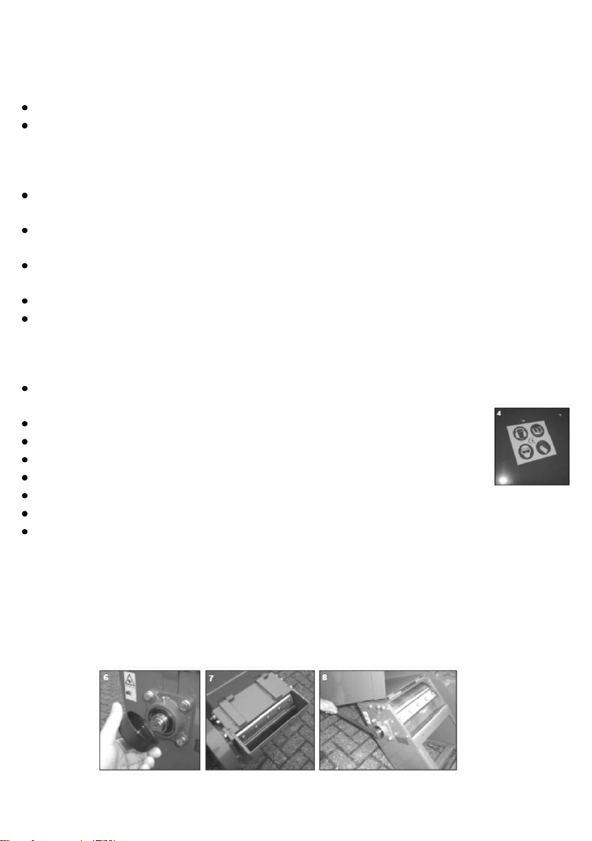
Pieces of wood lying crosswise in the input tube should only be removed when the
blades have stopped. In case the rotor is blocked by a piece of wood: remove the
ignition key, dismount the cover on the bearing housing of the rotor shaft and turn
the rotor is blocked by a piece of wood: remove the ignition key, dismount the cover
on the bearing housing of the rotor shaft and turn the rotor a few degrees by means
of the specially made spanner for this purpose. Then remove the cross-lying piece of
wood with another stick or implement DO NOT PUT YOUR HANDS IN THE ROTOR.
(fig. 6, 7 and 8).

7
Never leave the machine running unattended.
Stop the engine and remove the key from the ignition switch before replacing the
blades or the counter blade.
Check after one hour’s work that all bolts, nuts and screws are tight. If not, tighten
them or consult your dealer.
Always use original spare parts otherwise your warranty will be voided.
The machine should be repaired only by a service agent/dealer authorised by the
manufacturer.
2.2 Starting the chipper
Before starting the machine, always respect the instructions on Safety & Environment
(see chapter 1.2)
2.3 Using the chipper
Start the engine and let it warm up at 1/3 throttle for 1 minute. Then put the engine at full
throttle. Consult the engine manual on how to switch on the engine properly and the
correct use of the engine in the separate engine manual (fig. 9 and 10)
Put the branches into the input tube and when these are pulled in let go the branches. The
branches will be pulled in automatically. Feed thick branches in see that the engine revs are
maintained. Cut side branches thicker than 3cm off from the main branch and feed them
into the machine separately. Long branches could lash into your face, so keep at a distance
and always wear face protection.
PAY ATTENTION TO THE FOLLOWING REMARKS:
Do not hesitate to use the emergency switch (fig. 11) in case of emergency. For switching
off the machine normally, the engine should be allowed to idle first and then the key switch
should be put in the “0” or “Off” position.
The output tube must be tightly bolted on the machine at all times, so chips cannot be
slung away and nobody can get harmed.
TIPS WHILE CHIPPING
The hardness of the wood depends on the wood type, the time between pruning and chipping and
how dry the branches are. The machine performs best if the branches are chipped right after pruning.

8
Always check that the two bolts at the bottom of the input tube are securely tightened (fig.
12 & 13), if you wish to stop chipping allow the machine to run for several minutes to chip
and eject all debris which otherwise can jam the rotor when you next want to start the
machine.
2.4 Transporting
Before you move the machine, shut off the engine, remove the key from the switch and
remove the cap from the spark plug.
3. MAINTENANCE OF THE CHIPPER AND CHECKS
Before checking and servicing the machine, switch of the engine, remove the key from the
switch and remove the cap from the spark plug.
When cleaning the machine with a high pressure cleaner, never spray on the bearings. It
could damage the bearings and the machine, thereby void the warranty.
Grease/oil bearings, blades and rotor against corrosion before storing the machine.
Block the rotor with the special spanner on the axle of the rotor before servicing/working
on the rotor. Do test the emergency switch regularly.
Check the tire pressure and keep it at the right pressure (minimum 22psi, maximum 28psi).
Engine maintenance: please consult the engine manual (Subaru EX40DU) of the engine
manufacturer.
The chipper has parts weighing more than 20kg. Handling these parts should always be
done by two people to avoid risk of injury.
Parts heavier than 20kg:
Rotor housing +/- 27kg
Input tube +/- 29kg
Engine +/- 32kg
Rotor +/- 24kg

9
3.1 Removing the input tub
First remove the output tube by un-tightening the 2 Allen-screws (picture 1.1 & 1.2).
Then remove the Allen-screws from the input tube (picture 1.3). Tilt the input tube
backwards carefully (picture 1.4). Be aware that the machine could lose its balance –if
need be support the frame at the bumper (picture 1.5). If the input tube is tilted
backwards, it can be removed from the machine sideways (picture 1.6). Mount the input
tube by following the same steps in reverse order.
3.2 Replacing and Adjusting the belts
Remove the key from the switch before changing the belts.
Remove the cover from the belt housing. Loosen slightly the bolt that fixes the belt
housing to the rotor housing (picture 2.1).
Unscrew the bolts fixed horizontally to the engine (picture 2.2) Loosen slightly the bolts
that fix the engine on the chassis (picture 2.3).
Move the engine block to the back. Check that the belt housing is moving in the same
direction. Now it is simple to remove the old belts and to fit the new ones. Note that
once the belts are removed, it is easy to check the distance between blades and counter-
blades, because the rotor can turn freely.
Only use belts with the correct power transmission rating!
Tension the belts by moving the engine block forwards and, once the correct belt
tension is found, block the engine position by screwing tight the 4 bolts to the chassis.
Once you have got the right tension, check that the pulleys are in-line. You can see this
by holding a bar against the pulleys (picture 2.4 above). You have reached the right
tension when the belt can be pulled down +/- 6cm (2.5 inches).
When new belts are fitted the distance between pulley spindles should be +/- 730mm.
Check after tensioning the belts that the pulleys are in-line again. Check that all bolts are
tightened properly, especially the bolt holding the belt housing to the rotor housing. Put
the cover for the belt housing back in place and mount the input and output tubes.
After changing the belts, let the machine run for 5 minutes without load. While running
without load, check the machine for loose bolts, unusual noises or vibrations. Now the
machine is ready for use.

10
3.3 Changing the engine oil.
Change the engine oil at the recommended interval see engine user manual for
instructions. Fill the engine with SAE30 engine oil. Use funnel to avoid spillage.
4. PROBLEMS, CAUSES & SOLUTIONS
PROBLEM
CAUSE
SOLUTION
The shredder does
not perform
properly: the
wood is not pulled
in by the rotor
itself
The chips do not
have the same
size
- The blades are worn too much
- The diameter of the branches
inserted into the machine is too
large
- There is too big a gap between
the fixed blade and the counter
blade: correct gap is 0.5mm (half a
millimetre)
Reverse, sharpen or change the blades.
Remove branches thicker than 75mm.
Adjust the gap between fixed blade: and
counter blade: the correct gap is 0.5mm.
The engine does
not start/ the
engine shut off by
itself
- Electrical problem with engine
- No fuel
- No or not enough oil in the
engine (the oil should be level with
the threads of the filler hole).
Check that the start-switch on the engine is
on “on” or “I”.
Check if the emergency switch is de-activated
Check oil and fuel levels
Contact your dealer
The machine jams
during use
The engine will
not start/turn
because the rotor
is jammed
- the diameter of the branch is too
big
- there are unacceptable materials
such as stones or metal in the
input tube
Shut off the engine and remove the key from
the start switch. Remove the cap from the
rotor-axle. Turn the rotor a few degrees
counter-clock-wise by means of the special
spanner. Block the rotor by blocking the
special spanner on the rotor axle behind the
wheel axle. Remove material from the input
tube by means of a stick or tool and start the
machine again. If need be, change the
blades.
NEVER PUT YOUR HAND INTO THE INPUT
TUBE OR ROTOR
The machine does
not throw out
chips any more.
The output tube is
jammed
Too much wet material (leaves,
grass, rotten material) has been
fed into the machine
Shut off the engine, remove the spark plug
cap. Block the rotor-axle by blocking the
special spanner behind the wheel axle.
Dismount/remove the output tube.
Do not touch the blades, even if you are
wearing gloves! There is a high risk of cutting
your hands badly. Remove debris with a stick
or tool. Mount the output tube again, tighten
the screws firmly. Remove the special
spanner from the axle.
Fit the cap on the rotor axle. Start the engine
again.

11
6. PARTS DIAGRAM
5. TECHNICAL SPECIFICATIONS
GTS1300 Powered by a SUBARU EX40 14hp engine
Maximum RPM 3600
Dimensions –150L x 75W x 152H cm
Weight –165kg
Chipping system: 2 blades on rotor and 1 counter blade on chassis

12
7. SPARE PARTS LIST

13
8. SPARE PARTS LIST

14
9. WARRANTY
Consult the CROMMELINS Machinery warranty leaflet (supplied with your new product)
for full details and a list of service dealers for this product, also available online at
www.crommelins.com.au.

15
NOTES
.................................................................................................................................................
.................................................................................................................................................
.................................................................................................................................................
.................................................................................................................................................
.................................................................................................................................................
.................................................................................................................................................
.................................................................................................................................................
.................................................................................................................................................
.................................................................................................................................................
.................................................................................................................................................
.................................................................................................................................................
.................................................................................................................................................
.................................................................................................................................................
.................................................................................................................................................
.................................................................................................................................................
.................................................................................................................................................
.................................................................................................................................................
.................................................................................................................................................
.................................................................................................................................................
.................................................................................................................................................
.................................................................................................................................................

16
Table of contents
Popular Chipper manuals by other brands


TruYard
TruYard C150 Safety, operation & maintenance instructions

hillvert
hillvert HT-HECTOR 212 user manual

Briggs & Stratton
Briggs & Stratton CH8993H owner's manual

DK2 Power
DK2 Power OPT118 Assembly guide

AGRI EASE
AGRI EASE BE-WCGR3 Series Operations & parts manual

hillvert
hillvert HT-HECTOR 420T user manual

DR
DR 18 HP Safety & Operating Instructions

Hansa
Hansa C65RX Operation, maintenance and safety manual

Electrolux Professional
Electrolux Professional CF4 instruction manual

Farmi Forest Corporation
Farmi Forest Corporation 100F OPERATION, MAINTENANCE AND SPARE PARTS MANUAL

Sioux Tools
Sioux Tools 5264 instructions

hillvert
hillvert HT-HECTOR-6600 user manual