ABB LGR-ICOS GLA531 Series User manual

3KXG165002R4201_2021_04
GLA531 Series LGR-ICOSTM Gas
Analyzer Operating Manual
ABB Inc. Measurement & Analytics
3400, rue Pierre-Ardouin
Quebec, (Quebec) G1P 0B2 Canada
Tel: 1 800 858 3847 (NorthAmerica)
Tel: +1 418 877 2944 (Worldwide)
Fax: +1 418 877 2834
abb.com/analytical

GLA531 Series LGR-ICOSTM Gas Analyzer
Operating Manual
3KXG165002R4201_2021_04
ABB PROPRIETARY INFORMATION 2
Table of Contents
Disclaimers .........................................................................................................................................................4
Patent......................................................................................................................................................................4
Copyright................................................................................................................................................................4
Trademark..............................................................................................................................................................4
Warranty.................................................................................................................................................................4
Customer Support..................................................................................................................................................5
1Introduction ...............................................................................................................................................6
2General Safety...........................................................................................................................................7
Symbols..................................................................................................................................................................7
Laser Product Class...............................................................................................................................................8
Electrical Safety and Fuse.....................................................................................................................................8
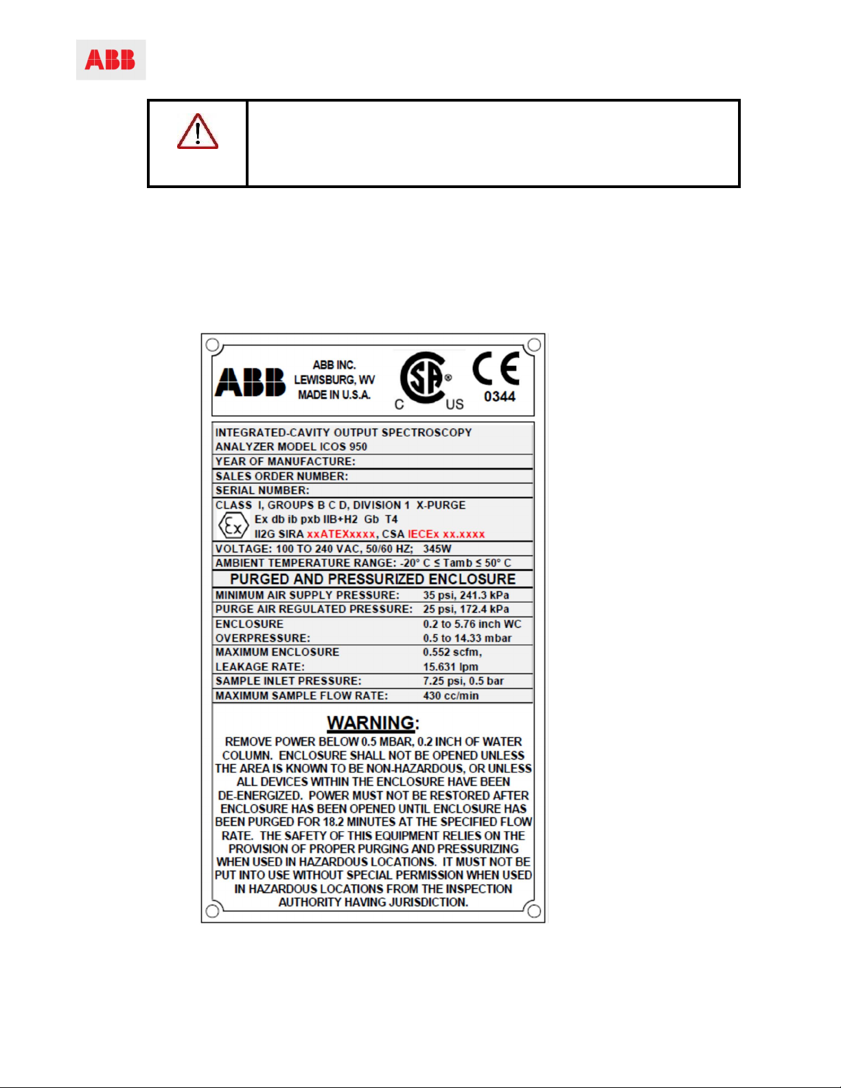
Certifications and Compliances.............................................................................................................................9
Operator Safety....................................................................................................................................................11
CDA Purge ......................................................................................................................................................11
N2Purge..........................................................................................................................................................12
Burn Hazards........................................................................................................................................................12
Laser Hazards......................................................................................................................................................13
Fire Safety Provisions..........................................................................................................................................14
WEEE Directive....................................................................................................................................................16
3Features and Theory of ICOS................................................................................................................17
Main Features.......................................................................................................................................................17
Theory of Operation.............................................................................................................................................17
LGR’s OA-ICOS...................................................................................................................................................19
4User Interface Operation........................................................................................................................20
Control Bar............................................................................................................................................................20
Display..................................................................................................................................................................21
Numeric Display...................................................................................................................................................21
Spectrum Display.................................................................................................................................................22
Time-chart Display...............................................................................................................................................23
Alarm Status Display............................................................................................................................................24
Rate Button...........................................................................................................................................................25
File Button.............................................................................................................................................................25
File Transfer .........................................................................................................................................................26
Setup Button.........................................................................................................................................................27
Time/Files.............................................................................................................................................................28
Calibration.............................................................................................................................................................30
Laser Adjust..........................................................................................................................................................31
4–20 mA Range Adjustment................................................................................................................................32
Service Screen.....................................................................................................................................................33
Shutting Down the Analyzer................................................................................................................................34
5Communications – Data and Alarms ...................................................................................................35
Input/Output Interface Hardware.........................................................................................................................35
Ethernet................................................................................................................................................................36
Modbus/TCP.........................................................................................................................................................36
USB Drive – Local Data Access..........................................................................................................................38

GLA531 Series LGR-ICOSTM Gas Analyzer
Operating Manual
3KXG165002R4201_2021_04
ABB PROPRIETARY INFORMATION 3
4–20 mA Isolated Analog Outputs......................................................................................................................39
6Purged-and-Pressurized Protection System for Flammable Gas....................................................42
Protection System Types for Analyzers..............................................................................................................43
X-Purge Type Protection System........................................................................................................................45
Z-Purge Type Protection System........................................................................................................................49
7Analyzer Hardware..................................................................................................................................54
Replaceable Hardware........................................................................................................................................55
AC-to-DC 24 V Power Supply Converter............................................................................................................56
DC/DC Voltage Converter...................................................................................................................................56
Temperature Controller........................................................................................................................................57
DC Solid-State Relay...........................................................................................................................................57
PC104 Computer Stack and Hard Drive.............................................................................................................58
4-20 mA Signal Isolators......................................................................................................................................59
Modbus/TCP.........................................................................................................................................................59
Two-Port Solenoid Driver-Board.........................................................................................................................62
Exhaust Pump......................................................................................................................................................63
Inlet Solenoid-Valve.............................................................................................................................................64
PWM Pressure Controller....................................................................................................................................64
EPC Valve ............................................................................................................................................................64
8Preventive Maintenance.........................................................................................................................65
Yearly Maintenance.............................................................................................................................................65
Five-Year Maintenance........................................................................................................................................65
Fifteen-Year Parts Replacement.........................................................................................................................66
9Basic Troubleshooting in ICOS Gas Measurements.........................................................................68
Gas Temperature.................................................................................................................................................68
Gas Pressure........................................................................................................................................................68
Laser Linelock and Self-Correction.....................................................................................................................68
Laser Path-Length and Astigmatic Mirrors.........................................................................................................69
Hardware Failures................................................................................................................................................70
Purge System.......................................................................................................................................................71

GLA531 Series LGR-ICOS™Gas Analyzer
Operating Manual
3KXG165002R4201_2021_04
ABB PROPRIETARY INFORMATION 4
Disclaimers
This document contains productspecifications and performancestatements that may be in conflict with other
ABB published literature, such as product flyers and product catalogs.All specifications, product characteristics,
and performance statements included in this document are given as suggested specifications only. In case of
conflict between product characteristics given in this document and specifications given in the officialABB
product catalogs, the latter takes precedence.
ABB reserves the right to make changes to the specifications ofall equipment and software, and to the contents
of this document, without obligation to notify any person or organization of such changes. Every effort has been
made to ensure that the information contained in this document is current and accurate. However, no guarantee
is given or implied that the document is error-free or that the information is accurate.
Patent
LGR-ICOSTM GasAnalyzer technology is protected by patents:
•7,468,797
•6,839,140
•6,795,190
•6,694,067
Copyright
© 2021 ABB Inc.All rights reserved. Information contained in this document may not be reproduced in any form,
in full or in part, without prior written consent fromABB.
Trademark
LGR-ICOSTM is a registered trademark ofABB Inc. Swagelok® is a registered trademark of Swagelok. Modbus®
is a registered trademark of SchneiderAutomation, Inc. LGR-ICOS® is a registered trademark of ABB, Inc.
Warranty
Refer to yourABB GLA531 Series LGR-ICOSTM GasAnalyzer’s unique sales contract for warranty
specifications.

Operating Manual
3KXG165002R4201_2021_04
ABB PROPRIETARY INFORMATION 5
GLA531 Series LGR-ICOS™Gas Analyzer
Customer Support
ABB provides product support services worldwide. To receive product support, either in or out of warranty, contact
theABB office that serves your geographical area, or the address indicated below:
ABB Inc. Measurement & Analytics
3400, rue Pierre-Ardouin
Quebec, (Quebec) G1P 0B2 Canada
Tel: 1 800 858 3847 (NorthAmerica)
Tel: +1 418 877 2944 (Worldwide)
Fax: +1 418 877 2834
Please contact icos.support@ca.abb.com and your local sales representative for more details.
IMPORTANT! Please be prepared to provide the serial number or sales order number of
the analyzer.

GLA531 Series LGR-ICOS™ Gas Analyzer
Operating Manual
3KXG165002R4201_2021_04
ABB PROPRIETARY INFORMATION 6
1Introduction
This document is a universal user manual for operatingABB GLA531 Series LGR-ICOS™ Gas Analyzer. It
also provides information on the operational safety, maintenance, troubleshooting, and calibrations. This
manual describes a fully loaded analyzer with all options. Youranalyzer may or may not have all the options
available.
Even though this operating manual provides information on the hardware components and their particular
functions, it is recommended to have qualifiedABB service personnel resolve issues with the analyzer.The
following lists manuals available forABB GLA531 Series LGR-ICOS™ Gas Analyzer, which may be used for
references:
•3KXG165002R4401, Commissioning Instructions
•3KXG165002R4201 Operating Instructions (this document)
ABB GLA531 Series LGR-ICOS™ Gas Analyzer offer three types of packaging configurations for different
installation locations.
•GLA531 GasAnalyzer with X-Purge Protection System: purged-and-pressurized safety enclosure for
flammable gas and fire hazards, normally specified for Class I Division 1 (or Zone 1) hazardous-area
location installations. FeaturesPower Interlock. Available with CDAor nitrogen purge options.
•GLA531 GasAnalyzer with Z-Purge Protection System: purged-and-pressurized safety enclosure for
flammable gas and fire hazards, normally specified for Class I Division 2 (or Zone 2) hazardous-area
location installations.Available with CDAor nitrogen purge options.
•General-Purpose GLA531 GasAnalyzers for non-flammable gas: only recommended for ordinary-
location installations, where there are no safety hazards to theoperators.

GLA531 Series LGR-ICOS™ Gas Analyzer
Operating Manual
3KXG165002R4201_2021_04
ABB PROPRIETARY INFORMATION 7
2General Safety
The following pages provide important safety precautions. Before starting repairs or hardware-related work on the
analyzer, read the safety information in this section.
Before opening the analyzer door, be sure that the area is safe. Contact the local Safety
Department to ensure that all safety guidelines, regulations, andprocedures are followed. This
includes obtaining theproper work permits and consulting the Material Safety Data Sheets for
safety requirements.
Before working on the analyzer, be prepared to work correctly with lethal voltages, infrared light
sources, hazardous gases, and hot surfaces.
Wear protective clothing and use protective equipment appropriate for the specific job.
When working on the analyzer, there is a possibility of exposure to hazardous samples as well as
nitrogen. Although nitrogen is an inert gas, itdoes not support human life. All appropriate
precautions and care should be taken.
Ensure that there is adequate ventilation while work isbeing done on the analyzer.
Because the actual configuration of the analyzer depends onthe application, this manual cannot
address all of theassociated safety problems. Itis the responsibility of the user to comply with all
applicable safety guidelines, regulations and procedures.
Refer to Table 1 for descriptions of the related safety symbols inthis document.
Symbols
The following symbols may be used in the documentation or on the analyzer:
Table 1 Documentation Safety Symbols
Symbols Meaning
NOTE or
IMPORTANT!
Emphasizes facts and conditions important to analyzer operation.
WARNING!
General warning or caution. Gives general safety information that must be followed to
avoid hazardous conditions.
WARNING!
Laser warning: potential laser hazards

GLA531 Series LGR-ICOS™ Gas Analyzer
Operating Manual
3KXG165002R4201_2021_04
ABB PROPRIETARY INFORMATION 8
Symbols Meaning
WARNING!
Hot Surface warning
WARNING!
Electrical warning: potential electrical shock hazardand high-voltage exposure
DANGER!
Danger: Failure to comply may result in serious injury or death.
Laser Product Class
NOTE This analyzer is a Class 1 laser product.
TheABB GLA531 Series LGR-ICOS™ Gas Analyzer is a Class 1 laser product when the front panel is closed.
Electrical Safety and Fuse
Electrical insulations and the analyzer enclosure protect operators from contact with hazardous voltages during
normal system operations. If a short circuit or other over-currentcondition occurs, the internal fuse protects the
analyzer and disconnects the power line from the incoming power source.
•TheAC powered analyzer is protected by a 5Afuse in the power-entry module, located at the upper
right-hand corner inside the analyzer enclosure.There are two high-voltage potentials operating above
30 volts RMS inside the enclosure: theAC power-entry module with the 5Afuse, and theAC-to-DC
voltage converter. These two locations are marked with electrical hazard labels.
•The 24 V DC powered analyzer is protected by a 15Abreaker-switch, located on the DIN rail at the
lower left-hand side corner inside the analyzer enclosure. Thereare no high-voltage potentials above
30 volts RMS in a DC powered analyzer.
WARNING!
Only authorized personnel are permitted to perform maintenance inside the
analyzer.
Follow the “Lockout-tagout” procedure when servicing the analyzer.

GLA531 Series LGR-ICOS™ Gas Analyzer
Operating Manual
3KXG165002R4201_2021_04
ABB PROPRIETARY INFORMATION 9
Certifications and Compliances
TheABB GLA531 Series LGR-ICOS™ Gas Analyzer offers the following certifications in Table 2 for
hazardous-location installations, flammable gas, and fire hazards.An example of a certification plate is shown
in Figure 1.
Table 2 ABB GLA531 Series LGR-ICOS™ Gas Analyzer Certifications for Hazardous Locations
Certification
X
-
Purge
Type
Protection System
Z
-
Purge
Type
Protection System
North American
Certifications
Class I Division 1 (or 2) Group B, C, D,
and Zone 1 (or 2) Group IIB+H2
Temperature Code T4
Class I Division 2 Group B, C, D, and
Zone 2 Group IIB+H2
Temperature Code T4
NEC and CEC, 61010
-
1,
NFPA496,
NEMA250,
UL1203
C22.2 No. 30
UL913,
C22.2 No. 157
UL60079-0
UL60079-1
UL60079-2
UL60079-11
NEC and CEC, 61010-1
NFPA496
NEMA250
ISA12.12.01
UL60079-0
UL60079-2
UL60079-15
II 2G Ex db ib pxb IIB+H2 T4 Gb
-20 C < Ta < +50C – IP54
ATEX Zone 1 or 2
2014/34/EUATEX Directive:
EN 60079-0, EN 60079-1, EN 60079-2,
EN 60079-11
EN 61010, EN 61010-2-101 Laser Safety,
EN 60825-1
2004/108/EC EMC Directive,
EN 61326-1
II 3G Ex pzc IIB+H2 T4 Gc
-20 C < Ta < +50C – IP54
ATEX Zone 2
2014/34/EUATEX Directive:
EN 60079-0, EN 60079-2,
EN 60079-15
EN 61010, EN 61010-2-101 Laser
Safety, EN 60825-1
2004/108/EC EMC Directive,
EN61326-1
IECEx Zone 1 or 2
Ex db ib pxb IIB+H2 T4 Gb Zone 2
Ex nApzc IIB+H2 T4 Gc
2014/35/EU (LVD), EN 61010-1
2004/108/EU (EMC), EN61326-1 2014/35/EU (LVD), EN 61010-1
2004/108/EU (EMC), EN61326-1
Title 21 Code of Federal Regulations,
chapter 1, sub-chapter J Title 21 Code of Federal Regulations,
chapter 1, sub-chapter J.

GLA531 Series LGR-ICOS™ Gas Analyzer
Operating Manual
3KXG165002R4201_2021_04
ABB PROPRIETARY INFORMATION 10
NOTE The analyzer is certified for Category II installation and Pollution Degree 2
devices.
For ordinary-location installations, the General-Purpose configuration is offered without the protection system for
fire hazards. It is a simplified product packaging for use in non-flammable environments, where sample gases are
not flammable. This General-Purpose analyzer complies with European CE Directives and 21 CFR Laser Safety
Regulations as listed above in Table 2.
Figure 1 Example of a Certification Plate for an Analyzer with X-Purge Protection System

Operating Manual
3KXG165002R4201_2021_04
ABB PROPRIETARY INFORMATION 11
GLA531 Series LGR-ICOS™ Gas Analyzer
Operator Safety
When the front panel is closed and locked into position,the analyzer is a safe instrument. Operating the analyzer
in any other condition may damage the equipment or injure personnel.
WARNING!
When configured with the toxic process gas H
2
S, the exhaust of protective
gas (air) and process gas shall be routed to a safe area.In the event of loss
of protective gas to the pressurized enclosure, the process gas flow should
be shut off.
Do not operate the analyzer with the front panel open:
•The front panel protects against electrical shock and accidental laser exposure to operators.
•ABB GLA531 Series LGR-ICOSTM GasAnalyzers with the purged-and-pressurized protection system for
flammable gas are designed to: 1) maintain a specificinternal pressurization, 2) continuously dilute the
atmosphere inside the enclosure to prevent any ignitions, and 3) prevent fire and explosion hazards.
•Do not bypass any safety procedures when the analyzer is extracting flammable gas or operating in a
flammable gas environment.
DANGER!
Bypassing the internal pressure switch and opening thefrontpanel during
analyzer operations may cause serious accidents, and possibly fire and/or
explosion hazards.
CDA Purge
WARNING!
REMOVE POWER BELOW 0.5 MBAR,0.2 INCH OF WATER COLUMN.
DO
NOT OPEN THEENCLOSURE UNLESS THEAREA IS KNOWN TO BE
NON-HAZARDOUS, OR UNLESSALLDEVICES WITHIN THE
ENCLOSURE HAVEBEEN DE-ENERGIZED. POWER MUST NOT BE
RESTORED AFTER THE ENCLOSURE HASBEEN OPENED UNTIL THE
ENCLOSURE HASBEEN PURGED FOR 18.2 MINUTESAT THE
SPECIFIED FLOW RATE. THE SAFETY OF THIS EQUIPMENT RELIES
ON THEPROVISION OF PROPER PURGING AND PRESSURIZING WHEN
USED IN HAZARDOUS LOCATIONS. IT MUST NOT BE PUT INTO USE
WITHOUT SPECIALPERMISSION FROM THE INSPECTIONAUTHORITY
HAVING JURISDICTION WHEN USED IN HAZARDOUS LOCATIONS.

Operating Manual
3KXG165002R4201_2021_04
ABB PROPRIETARY INFORMATION 12
GLA531 Series LGR-ICOS™ Gas Analyzer
N2Purge
WARNING!
PRESSURIZED ENCLOSURE. PROTECTIVE GAS IS NITROGEN. THIS
ENCLOSURE CONTAINS INERT GASAND MAYBEAN ASPHYXIATION
HAZARD. THIS ENCLOSURE ALSO CONTAINSA FLAMMABLE
SUBSTANCETHAT MAY BEWITHIN THE FLAMMABLELIMITS WHEN
EXPOSED TO AIR.
REMOVE POWER BELOW 0.5 MBAR,0.2 INCH OF WATER COLUMN.
DO NOT OPEN THEENCLOSURE UNLESS THEAREAIS KNOWN TO BE
NON-HAZARDOUS, OR UNLESSALLDEVICES WITHIN THE
ENCLOSURE HAVEBEEN DE-ENERGIZED. POWER MUST NOT BE
RESTORED AFTER THE ENCLOSURE HASBEEN OPENED UNTIL THE
ENCLOSURE HASBEEN PURGED FOR 36.4 MINUTESAT THE
SPECIFIED FLOW RATE. THE SAFETY OF THIS EQUIPMENT RELIES
ON THEPROVISION OF PROPER PURGING AND PRESSURIZING WHEN
USED IN HAZARDOUS LOCATIONS. IT MUST NOT BE PUT INTO USE
WITHOUT SPECIALPERMISSION FROM THE INSPECTIONAUTHORITY
HAVING JURISDICTION WHEN USED IN HAZARDOUS LOCATIONS.
Burn Hazards
The analyzer is designed to receive high-temperature gas up to 105 °C at the inlet gas bulkhead.The ICOS
Module is heated, and its internal temperature is maintained during normal operations. If controller malfunction or
temperature over-run occurs, the ICOS Module heaters may reach approximately 90 °C. The temperature set-
point of the ICOS Module depends on the measured gas species. Burn hazard labels are located near the inlet
gas bulkhead (as applicable) and the ICOS Module tohelp identify burn hazards inside the analyzer.
WARNING!
Allow the systemto cool down before performing any maintenance work.
Burn hazards may be present during replacement or service of the ICOS
heaters, filters, thermocouples, and solenoidvalves.
Figure 2 Burn Hazard Label and Location

GLA531 Series LGR-ICOS™ Gas Analyzer
Operating Manual
3KXG165002R4201_2021_04
ABB PROPRIETARY INFORMATION 13
Laser Hazards
Up to two lasers are used in theABB GLA531 Series LGR-ICOS™ Gas Analyzer The laser wavelength depends
on the species of gas measured. Under normal operation, with the analyzer front panel closed, the spectroscopy
device is a Class 1 Laser Product in accordance with Title 21 Code of Federal Regulations, chapter 1,
sub-chapter J.
The analyzer lasers are rated as Class 3B (>5 mW) when exposed.All lasers are enclosed in the ICOS Module
and not accessible during normal operations. Removing the laser enclosure (or cover) automatically triggers a
safety interlock and shuts down the lasers (refer to Figure 3). Laser warning labels are on the ICOS Module
enclosure covering the laser(s).
Lasers in the ICOS Module are not field-serviceable.If a laser fails in the field, the entire ICOS Module assembly
must be replaced. Only one component in the ICOSModule is user serviceable: The spectroscopy mirrors may
be cleaned during preventive maintenance (PM).
Figure 3 Laser Radiation Labels and Interlock Switch
WARNING!
Lasers inside the ICOS Module are classified as Class 3Bwhen accessed.
Only trained service personnel are authorized to open and service the ICOS
Module.

Operating Manual
3KXG165002R4201_2021_04
ABB PROPRIETARY INFORMATION 14
GLA531 Series LGR-ICOS™ Gas Analyzer
Fire Safety Provisions
Small amounts of methanol and acetone are used to clean optical components in the analyzer during
maintenance. The typical amount used is less than 25 millilitersper solvent. These solvents present a fire hazard.
Only use these solvents in accordance with local regulations and standards. Do not use these chemicals near
open flames, sparks, or heaters. Soaked wipes must be disposed according to the requirements of 40 CFR, local
fire department and environmental jurisdictions.
Follow these precautions whendealing with flammable chemicals:
•Keep all chemical containers away from heat, sparks, and open flames.
•Only apply on grounded equipment or components.
•Use non-sparking tools when in contact with the chemical.
•Store in a cool, dry, well-ventilated place, away from incompatible materials.
If a spill occurs:
•Make sure all handling equipment is electrically grounded.
•Mop or wipe up, then place all chemical-soaked items in containers approved by the US Department of
Transportation (DOT)or the appropriate local regulatory agency.
Figure 4 Heavy Object Label
This label is located on the external right side panel of the enclosure.
Figure 5 Pinch Point Label
This label is located on the ICOS-Module covers (near the latch snaps), and on the right side panel of the
enclosure (near the door closing position).

Operating Manual
3KXG165002R4201_2021_04
ABB PROPRIETARY INFORMATION 15
GLA531 Series LGR-ICOS™ Gas Analyzer
Figure 6 High Voltage Label
This label is located on the internal right-side panel, next to theAC power terminal block and theAC power-entry
module.
Figure 7 Laser Radiation Label
These labels are located on the ICOS-Module covers (see Figure 3).
Figure 8 Burn Hazard Label
This label is located on the ICOS Module cover.
Figure 9 Fire Hazard Label
Warning for the cleaningsolvents used for cleaning the ICOS optical mirror.

Operating Manual
3KXG165002R4201_2021_04
ABB PROPRIETARY INFORMATION 16
GLA531 Series LGR-ICOS™ Gas Analyzer
WEEE Directive
TheABB GLA531 Series LGR-ICOS™ Gas Analyzer is not subjected to WEEE Directive 2002/96/EC (Waste
Electrical and Electronic Equipment) or relevant national laws (for example, ElektroG in Germany).
The product must be disposed ofat a specialized recycling facility. Do not use municipal garbage collection
points.According to the WEEE Directive 2002/96/EC, only products used in private applications may be disposed
of at municipal garbage facilities. Proper disposal prevents negative effects on people and the environment, and
supports the re-use of valuable raw materials.

GLA531 Series LGR-ICOS™ Gas Analyzer
Operating Manual
3KXG165002R4201_2021_04
ABB PROPRIETARY INFORMATION 17
3Features and Theory of ICOS
TheABB GLA531 Series LGR-ICOS™ Gas Analyzer is a laser-based spectroscopy instrument. The LGR-
ICOSTM cavity design enhances the detection of laser light absorption by the targeted gas molecules.The
enhancement improves the signal-to-noise ratio over conventional laser sensors, enabling robust
measurements and precise monitoring of trace gases. The laser wavelength of the analyzerdepends on the
target gas species.All measurements are in real time.
Main Features
The analyzer main features are:
•Designed for HazardousArea installations, which require robustoperations and minimal maintenance.
•Flexible configurations which can be customized forvarious types of background gases and unique
requirements.
•Fast-response measurements with a refresh rate of less than 15 seconds.
•High-accuracy and high-precision measurements,without requiring frequent calibrations.
•Large HMI screen with Touchscreen control.
Figure 10 GLA531 Series ICOS Cell Basic Plumbing Diagram
Theory of Operation
For gas measurements based on conventional laser-absorptionspectroscopy (see Figure 11), a laser beam is
directed through a sample, and the mixing ratio (ormole fraction) of a gas is determined from the measured
absorption using Beer’s Law, which may be expressed with Equation 1.
Equation 1
=
where: Iv= transmitted intensity through the sample at frequency v
Io= (reference) laser intensity prior to entering the cell

GLA531 Series LGR-ICOS™ Gas Analyzer
Operating Manual
3KXG165002R4201_2021_04
ABB PROPRIETARY INFORMATION 18
S= absorption line strength of the probed transition
L= optical path length of the laser beam through the sample
X= mole fraction
P= gas pressure
Φv= line-shape function of the transition at frequencyv
In this case:
Equation 2 ∫()=
If the laser line width is much narrower than the width of the absorption feature, high-resolution absorption
spectra may be recorded by tuning the laser wavelength over the probed feature.
Integration of the measured spectra with the measured values of:
•Gas temperature
•Gas pressure
•Path length
•Line strength of the probed transition
allows calculations to determine the mole fraction directly from the relation:
Equation 3 =
∫
This equation determines gas concentrations, even inhostile environments, without using calibration gases or
reference standards.
The values measured are:
•Mixtures containing several species
•Flows at elevated temperatures and pressures
Figure 11 TypicalLaser Absorption Spectroscopy Setup

Operating Manual
3KXG165002R4201_2021_04
ABB PROPRIETARY INFORMATION 19
GLA531 Series LGR-ICOS™ Gas Analyzer
ABB’s OA-ICOS
Off-Axis Integrated-Cavity Output Spectroscopy (OA-ICOS) uses a high-finesse optical cavity as an absorption
cell as shown in Figure 12. Unlike multi-pass detectors, typically limited to path lengths of less than 200 meters,
an OA-ICOS absorption cell effectivelytraps the laser photon sothat, on average, it makes thousands of passes
before leaving the cell.
As a result, the effective optical path length may be several thousand meters using high-reflectivity mirrors and
thus, the measured absorption oflight after it passes through the optical cavity is significantly enhanced. For
example, for a cell composed of two 99.99% reflectivity mirrors25 cm apart, the effective optical path length is
2500 meters.
Because the path length depends only on optical losses in the cavity and not on a unique beam trajectory (like
conventional multi-pass cells or cavity-ring-down systems), the optical alignment is very robust, allowing for
reliable operation in the field. The effective optical path length is determined routinely by simply switching the
laser off and measuring the necessary time for light to leave thecavity (typically tens of microseconds).
As with conventional tunable-laser absorption-spectroscopy methods:
•The laser wavelength selection is based on the selected absorption feature of the target gas to be
measured.
•The measured absorption spectra is recorded and used to determine a quantitative measurement of mixing
ratio directly and without external calibration when combined with the recorded:
üMeasured gas temperature and pressure in the cell
üEffective path length
üKnown line strength
Figure 12 OA-ICOS Analyzer Schematic Diagram

GLA531 Series LGR-ICOS™ Gas Analyzer
Operating Manual
3KXG165002R4201_2021_04
ABB PROPRIETARY INFORMATION 20
4User Interface Operation
Upon powering up the system, the HMI screen displays the program-loading screen, as shown in Figure 13.
Figure 13 Program Loading Screen
After the programs are loaded, the analyzer launches a Numericscreen, which displays gas concentrations (as
shown in Figure 16).At cold start, the screen may display a warning or possibly an alarm. It takes approximately
20 to 30 minutes for the heaters to reach their set temperatures.The two status bars on this screen turn green
after the set temperatures are reached.
Control Bar
The Control Bar (shown in Figure 14 and Figure 15) lets you select the type of screen to display. When the
analyzer first starts, you can only access the displaysand cannot make any changes (including shutting down the
analyzer) until you log in. To log in, click the Security button (far left) and enter username and password
credentials. Once logged in, new menu options are available, as shown in Figure 15.The selections from left to
right are: security login, measurement displays, sampling rates, file transfer, system setup, and exit.To select an
option, either: 1) tap the desired button on the touchscreen, or 2) use a keyboard/mouse to move the pointer to
the desired button, then click the button.
NOTE
Avoid alternating between the mouse and touchscreen for zoom control.
Touchscreen functionality should primarily be used for visualization of trends,
values, and alarms.
Table of contents
Other ABB Measuring Instrument manuals

ABB
ABB SensyMaster FMT230 User manual

ABB
ABB ISL-C 600 User manual

ABB
ABB Navigator 600 Silica User manual

ABB
ABB MagMaster MF/F Quick start guide

ABB
ABB C13 User manual

ABB
ABB AnalyzeIT ZMT Series Operating instructions

ABB
ABB ACF-NT User manual

ABB
ABB AnalyzeIT 7600 Series User manual

ABB
ABB ReliaMod RTBCOVER User manual

ABB
ABB EL3060 Series User manual

ABB
ABB ZEE600 User manual

ABB
ABB SM500F User manual

ABB
ABB CM-ENS User manual

ABB
ABB MAG-X 3000 Series User manual

ABB
ABB Comem eOLI22 User manual

ABB
ABB PointMaster 200 Series User manual

ABB
ABB ACX Installation and operation manual

ABB
ABB SM1000 User manual

ABB
ABB CoriolisMaster FCM2000 User manual

ABB
ABB Navigator 550 User manual