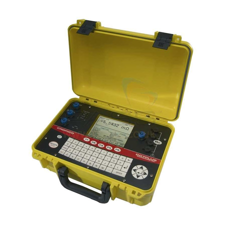
Cropico DO6 User manual

DO6Handbook
Jan2006 1of 107 pages
Contents
1. Introduction
•Use
•Description
2. Preparationsforuse
•Unpackingtheunit
•Usingtheinstrumentforthefirsttime
•Supplyvoltage, powerswitchandmainsfuse
•Powersupplyandsignal-cableconnectors
•Blockdiagram
•Setup and installation
•Functionaltest
•Calibration
•Storage
3. Safetyinstructions
4. Controls
•Frontpanel
•Buttonfunctions
•Rearpanel
•Descriptionof connectorsockets
5. Operatinginstructionsinbrief
6. Operation
•Meaningof theindividualdisplaysegments
•Setup menu
•Configurationmenu
•Measurementmenu
•Descriptionof theindividualsetupmenus
•Measuring range
•Limits
•Loadselection
•Handlinginductiveloads
•Measurementmode
•Continuousoperation
•Singleshot
•Alternatingmeasurementmode
•Coolingcurve
•Temperaturecompensation
•Autozero/Manual zero
•Deviceprogram
•Comparator
•Contrast
•Temperaturesensor
•Displaycounts
•Selftest
•Dataoutput
•Access topassword
•Interface
•Reference temperature
•Reference length
•Calibration

DO6Handbook
Jan2006 2of 107 pages
7. Controllingtheinstrumentremotely
•Controllingtheinstrumentvia thePLCinterface
•Controllingtheinstrumentvia theRS232 interface
•Connectorpin-outfortheRS232
•Interface parameters
•Communicationsprotocol
•Establishingaconnection
•Selectionwithresponse
•Fastselection
•Polling
•Datatransfer
•Terminatingaconnection
•Examplesof thecommunicationsequence
•Coolingcurve
•Communicationusing“Fastselection”
•Generalinformation
•Interface watchdogtimer
•TimerA(responsetimer)
•TimerB(receivetimer)
8. SCPIcommands
•Generalinformation
•SCPIRegisters
•ACCess Subsystem
•ACCess:LEVel
•DISPlaySubsystem
•DISPlay:CONTrast
•CALCulateSubsystem
•CALCulate:LIMit:STATe
•CALCulate:LIMit:RELais
•CALCulate:LIMit:FAULt
•CALCulate:LIMit:RESet
•CALCulate:LIMit:LOWer
•CALCulate:LIMit:ACKNowledge
•CALCulate:LIMit:CONTrol:DATA
•CALCulate:LIMit:MATH[EXPRession]
•RegisterSubsystem
•REGister:OUTPut
•REGister:INPut
•SCALESubsystem
•SCALE:VOLTage
•SCALE:PT100
•HCOPySubsystem
•HCOPyDESTination
•CCURveSubsystem
•CCURve:TIME:END
•CCURve:TIME:DELTa
•CCURve:TIME:COUNt
•CCURve:TIME:DATA
•CCURve:TIME:CHARge
•CCURve:INITiate
•CCURve:ABORt
•TRACeSubsystem
•TRACe:DATA:LENGth
•TRIGgerSubsystems
•ABORT
•INITiate[IMMediate]
•INITiate:CONTinuous
•FETCh?

DO6Handbook
Jan2006 3of 107 pages
•SYSTemSubsystem
•SYSTem:VERSion?
•SYSTem:LANGuage
•SYSTem:PASSword
•SYSTem:ERRor[NEXT]
•STATusSubsystem
•STATus:PRESet
•STATus:OPERation:ENABle
•STATus:QUEStionable:ENABle
•STATus:OPERation:CONDition?
•STATus:QUEStionable:CONDition?
•STATus:OPERational[EVENT]?
•STATus:QUEStionable:[EVENT]?
•SENSeSubsystem
•SENSe:TCOMpensate
•SENSe:TCOMpensate:STATe
•SENSe:TCOMpensate:TEMperature
•SENSe:TCOMpensate:TEMperature:REFerence
•SENSe:TCOMpensate:TCOefficient:SELect
•SENSe:TCOMpensate:TCOefficient:USER:CHANge
•SENSe:FRESistance:RESolution
•SENSe:FRESistance:MODE
•SENSe:FRESistance:TIME:CONStant
•SENSe:FRESistance:RANGe?
•SENSe:FRESistance:RANGe:AUTo
•SENSe:FRESistance:RANGe:UPPer
•SENSe:FRESistance:RANGe:LOWer
•SENSe:FRESistance:RANGe:MANual
•SENSe:AVERage:COUNt
•SENSe:CORRection:OFFset
•SENSe:CORRection:OFFset:AUTO:STATe
•IEE-448.2Commands
•*SRECommand
•*STB?Command
•*ESECommand
•*ESR?Command
•*OPCCommand
•*RSTCommand
•*TST?Command
•*WAICommand
•*CLSCommand
•*IDN?Command
•*RCLCommand
•Programmingexamples
•Communicationusing“Selectionwithresponse”
•Communicationusing“Fastselection”
9. Maintenance, Customerservice, Shipping,Cleaning
10. Appendix
•Technicaldata
•Calibration
•Errormessagesand troubleshooting

DO6Handbook
Jan2006 4of 107 pages
1. Introduction
1.1Use
Fastandaccuratemeasurementsofultra-smallresistancescanbemadeusing theDO6
milliohmmeter. Withitsruggedtable-topcaseandmembranekeypad, thisinstrumentis
designedforbothlaboratoryuseandharshindustrialenvironments.
Temperature-compensatedresistance-testingofwiresandcoilsispossibleusing aPt100
sensororpyrometertomeasurehetemperatureofthedevice undertest.Heinstrumentthen
corrects theresistance toe.g. 20°C(selectable)
Themeterhasahugerangeofapplications, suchasmeasuring:
•Transformer/motorwindings
•Coilsofanykind
•Cablesandwiresonthedrumorasmetersamples
•Switchandrelaycontacts
•Heatingelements
•Connectionsandcontacts topowerrails, and
•muchmore
CompletecontrolcapabilityviatheRS232 PCinterface meansthatfullyautomatictest
stationscanbesetup.ThemeterincludesaPLCinterface forintegrationinproduction
process controllers. A2-waycomparatorwithPLCandrelayswitching outputsisalso
providedforclassificationandselectionofthedevicesundertest.
1.2Description
Themeterworks onthebasisoftheproven4-wiremeasurementmethod, inwhichtest-lead
resistancesandcontactresistancesareeliminated. Themeasurementtechniquealso
compensatesautomaticallyforanythermalEMF’s inthemeasurementcircuit. The
instrumentleadsaremonitoredfordamagebyabuilt-indetector.
Ofcoursethemeterincludestemperaturecompensationforanytypeofmaterialundertest
suchascopper,aluminium,brass, tungstenetc. usinganexternalPt100 sensororexternal
infraredthermometer(accessory)tomeasurethetemperature.Aspecialcircuitforprotecting
themeasurementinputwhenmeasuring high-inductivedeviceshasbeendevelopedtoprevent
damagetothemeterfromvoltagepeaksproducedwhendisconnectingthedevice undertest.
Ifthereisarequirementtotestdevicesusing differentparametersinanautomatictestsetup,
thenup to16 device settingssuchasmeasuring range,limits, temperaturecoefficientetc. can
besaved. Alldevice-specificsettingsareshownonthedisplay.
ThesettingscanberetrievedviathekeyboardorPLCinterface using abitpattern(4bits).Of
coursealldevice settingscanalsobemadeviatheRS232 interface.
Abacklit, highcontrastLCDdisplayisusedfordisplaying thereadings, soitisextremely
easytoreadthemeasurementinbothdarkandwelllitrooms.

DO6Handbook
Jan2006 5of 107 pages
2. Preparations foruse
2.1Unpackingtheunit
Theinstrumentweighs3.5kg andispackedaccordinglytoprotectagainstshock.Unpackthe
instrumentcarefullyandverifythatallitemsarepresent.
Thisnormallyincludes:1DO6instrument
1Powerlead
1Copyofthismanual
Pleaseinspecttheinstrumentcarefullyfordamagethatmighthavehappenedintransit. Ifyou
suspectthattheinstrumenthasbeendamagedduringshipping,youshouldcontactthe
deliverycompanyimmediately. Thepacking shouldberetainedforinspectionbythe
manufacturer/deliverycompany. TheDO6milliohmmetershouldbeshippedonlyinits
originalpacking orinpacking capableofprovidinganequivalentdegree ofprotection.
2.2Usingtheinstrumentforthefirsttime
Ifcondensationhasformedontheinstrument, makesurethattheinstrumentiscompletelydry
(includinginside)beforeswitching iton.Connecttheinstrumenttoastandardgrounding
outletusingthepowerleadsupplied.
Warning: Theinstrumentmustneverbeswitchedonifitshowssignsofdamageduring
shipping. Thecaseormeasurementinputcancarrylife-threatening voltages
ifthemainsvoltageistransferredasaresultofdamage.
2.3Supplyvoltage, power switchand mains fuse
230V+6%-10%45….65 Hz, approx30VA
Themainsfuseislocatedbetweenthe
mainssocketsandpowerswitchontherear
oftheunit. Makesurethattheunitis
fullydisconnectedfromtheelectrical
mainsbeforechangingthefuse. This
shouldbedonebyremoving thepowerlead
fromthemainssocket;alwayspull onthe
connectoritself,neverthecable.
Onlyuseoriginalfuses5x20 mm 0.63 AT

DO6Handbook
Jan2006 6of 107 pages
2.4Power supplyand signal-leadconnectors
•Onlyeveruseashielded, twistedcablewithshieldedconnectorsforconnectingtothestandard
RS232 interface connector.
•AlwaysuseaPt100sensorwithshieldedcabletoconnecttothePt100 connector.Thecable
shieldmustnotbeincontactwiththeconnectorshellifgroundingofthesensorisunclear.
Otherwisecurrentscirculatinginagroundloopcancausemeasuringerrors.
•Onlyonedevice undertestmustbeconnectedacross thetwoparallelmeasurement
inputs. Noleadsmustbepluggedintotheunusedconnectorforsafetyreasons.
Additionalprotectionof themeasurementcurrentusingasuper
quick-acting 10 Afuse6.3x32mm
600 VAC
50000 Abreakingcapacity(orgreater)
Useonlythisfuse

DO6Handbook
Jan2006 7of 107 pages
2.5Blockdiagram

DO6Handbook
Jan2006 8of 107 pages
2.6Setupand installation
•Ensurethatthereisanadequatesupplyofairtopreventheatbuilding up intheinstrument
•Donotplace theinstrumentonsurfacessuchascarpets orcloths,ornearmaterialssuchas
curtainsorwallhangingsthatcouldpreventtheaircirculating
•Donotplace theinstrumentataninclinedangle;itshouldalwaysbeusedinahorizontalposition
•Keeptheinstrumentawayfromapparatus, equipment, machinesandinstallationsthatgenerate
strongmagneticfields
•Donotplace heavyobjectsontheinstrument
•Condensationcanforminsidetheinstrumentifitistakenfromawarmroomintoacoldroom;
waitafewhoursbeforeswitching ontheinstrument
•Makesurethatthedisplaypanelisnotmechanicallystressed
•Theinstrumentmusthavereachedthermalequilibrium
•Selecttheinstallationlocationsothattheinstrumentisnotexposedtoextremetemperatures
(operatingtemperaturerange0to50°C)ortemperaturevariations, nortohumidity, directsunlight,
incandescentlamps, dust, oils, organicsolvents,otheraerosols, severevibrationsormechanical
shocks. Inverydirtyindustrialenvironments, itisrecommendedtouseasuitableprotective
enclosure.
2.7Functiontest
Afterswitching ontheinstrument,thefollowing textappearsonthedisplayforabout3seconds:
Thentheinstrumentswitchesdirectlytothemeasurementmenu.
2.8Calibration
Themeterwascalibratedbeforeshipping. Thecalibrationhistoryoftheinstrumentsusedforthe
calibrationcanbetracedtothegovernmentmeasurementstandardinaccordancewithDINISO
9000 ff. Themetershouldberecalibratedafteraperiodofaboutoneyear. Calibrationis
performedusing theRS232 interface, andshouldonlybeperformedatthemanufacturers
premises. Thecustomercanperformthecalibrationin-housebypurchasing thePCsoftware
DO6-P001.
2.9Storage
Forlongtermstorage, packtheunit, alongwithadesiccant, intoanairtight, sealedpolythene
bag. Donotstoretheunitwhereitwillbeexposedtosunlightoranyotherlightsources.Take
caretoensurethatnothingcomesincontactwiththedisplaypanel. Thestoragetemperature
rangeis0to70°C;however, tomaximisethelifespanofthedisplay, thetemperatureshouldnot
exceed50°C.

DO6Handbook
Jan2006 9of 107 pages
3. Safetyinstructions
Whilstthehardwareandsoftwarehasbeendevelopedtoahighspecificationandthoroughly
tested,theycannotbetotallyguaranteedtobefree oferrors.Thusthisinstrument,orpartofthe
instrument, mustnotbeusedtoinfluence acontrolsystemfromwhichrisktolifeorpropertycan
arisedirectlyorindirectly, withoutadditionalprotection. Maintenanceandrepairworkmust
onlybeperformedbytrained, competent,technicalpersonnelfamiliarwiththeassociatedrisks.
•Theinstrumenthas2measurementinputsconnectedinparallel; onlyoneoftheseinputsmustbe
usedatanyonetime. Noleadsmustbepluggedintotheunusedconnectorforsafetyreasons.
Theunusedcircularsocketmustbecoveredwiththecapsupplied.
•Beforestartinganymeasurement, makesurethatthedevice undertestdoesnotcarryanexternal
voltage(e.g. mainsvoltage, voltagegeneratedbyarotatingmotoretc.)
•Takecarewhenhandling inductivedevicesundertest.Bythephysicalnatureofthesedevices,
life-threatening inductionvoltagescanbegeneratedwhenthetestcurrentisdisconnected.Read
theinstructionsinthe“Loadselection”section.
•Toavoidelectricshock, neveropenthecase. Theinstrumentcontainsnocomponentsthatcan
bemaintained, adjustedorcalibratedbythecustomer. Theinstrumentcanoperatewithall
standardmainsvoltagesintheworldwithoutneedingtobeswitchedover.
•Alwaysreplacefuseswithfusesofthesametype. Neverusefuseswithdifferentcharacteristics
orotherrelatedcurrents.Beforechanging thefuse, pulloutthemainsplug andshort-circuitthe
device undertest.
•Shouldforeignbodiesorliquidsgetinsidetheunit, disconnectthemainlead. Gettheinstrument
checkedoverbyqualifiedtechnicalpersonnelbeforeusingitagain.
•Alwaysleaverepairworktoqualifiedtechnicalpersonnel.
•Ifyoudonotintendusing theinstrumentforaprolongedperiod,takethemainsplug outofthe
socket.Alwayspullontheconnectoritself, neverthecable.
•Shouldliquidfromabrokendisplayescapefromtheunitandgetonyourhands, washyour
handsthoroughlyusing soapandwater.Removeanyresiduesoftheliquidwithacetoneor
ethanol.
•Alwayskeeptheinstrumentoutofrainorawayfrommoisturetopreventafirehazardortherisk
ofelectricshock.
•Checkthemainsleadbeforeuse.

DO6Handbook
Jan2006 10of 107 pages
4. Controls
4.1Frontpanel
FrontPanelwithbacklitLCDdisplayandintegralmembrane
keypadwithtactilefeedback
4.2Buttonfunctions
[START]Inthemeasurementmenuthisbuttonstartsameasurement.
Intheconfigurationmenuthisbuttonisassigneddifferentfunctionsdependingon
thetextshownonthedisplayabovethebutton(softkey).
[STOP] Inthemeasurementmenuthisbuttonstopsameasurement.
Intheconfigurationmenuthisbuttonisassigneddifferentfunctionsdependingon
thetextshownonthedisplayabovethebutton(softkey).
[] Inthemeasurementmenuandformanualrangeselectionthisbuttoncanbeused
toincreasethemeasuringrange.
Intheconfigurationmenuthisbuttonhasacurser(up)function.
[↓] Inthemeasurementmenuandformanualrangeselectionthisbuttoncanbeused
todecreasethemeasuring range.
Intheconfigurationmenuthisbuttonhasacurser(down)function.
[] Pressingbothbuttonssimultaneously
[↓] openstheConfigurationmenu

DO6Handbook
Jan2006 11of 107 pages
4.2Rearpanel
4.2.1Descriptionofconnectorsockets
Measurementinput 1 +U
2 +I
3 AnalogueGND
4 -I
5 -U
Connectorshell: PE(Protectiveground)
potential
Matingconnector: Burstertype9900-V172
Note: Thecurrentbranchis
protectedbyafuse6.3x32
mm10AFF. (Rearsideof
unit)
- IisatFE potential
Caution!Onlyonemeasurement inputmustbeusedatanyone time. Noleadsmustbe
pluggedintotheunusedinputforsafetyreasons.
Pt100 input 1 +U
2 +I
3 -I
4 Functionalground
5 Functionalground
6 -U
Connectorshell: PE(Protectiveground)
potential
Matingconnector: Burstertype4291-0
Two-wiretechnologyispossibleiftherelevant
conductorsarejoinedtogetheratthesensor.

DO6Handbook
Jan2006 12of 107 pages
Note:NEVERconnectthecableshieldtotheconnectorshell ifthegroundingatthesensorendis
unclear. Otherwise,ifthereisagroundconnectionatthetemperaturesensor, measuring errors
mayresultfromcirculatingground-loopcurrents.(Connectorshell isprotectiveground)
RS232 interface
1 NC
2 TXD
3 RXD
4
5 DigitalGND (groundedinternally)
6
7 NC
8
9 NC
Connectorshell: PE potential
Matingconnector:Type9900-V209
Matching datacable: Type9900-K333
Connectedininstrument

DO6Handbook
Jan2006 13of 107 pages
5. Operatinginstructions inbrief
Afterswitching ontheinstrument,theoperatinglanguagecanbeselectedintheidentification
menu.
Pressingbotharrowbuttonssimultaneouslyopenstheconfigurationprogram. ENTERconfirms
theselectedmenuoption. ESCcanbeusedtoreturnfromanyoptionintheconfigurationmenu
backtothenextmenuoptiondown. Ifavalueneedstobechangede.g. limit, arrowsappear
abovetheSTART/STOPbuttonstomovethecursortotheleft/right. Thenumericalvalueis
changedusingtheup/downarrowbuttons(ontherighthandside)onthefrontpanel.
Meas.range
Automaticrange1…4
20.000mΩ
200.00 mΩ
2.0000 Ω
20.000 Ω
200.00 Ω
2.0000 kΩ
20.000 kΩ
200.00 kΩ
Thelimitationof theautorangemodeis
onlypossiblewiththePCsoftware.With
thislimitationyougetintheautorange
modeahighermeasurementspeed. (e.g.
range1…4)
Limitvalue Upperlimit
Lowerlimit
xxx.xxxx yΩ
xxx.xxxx yΩ
Load
Resistiveload:Z1(littletimeconstant)
Inductiveload:Z2(middletimeconstant)
Inductiveload:Z3(hightimeconstant)
Meas.mode Continuous
Singleshot
Alternating
Coolingcurve
Averageof xx values
xxx valueafterstart
Averageof xx values
Intervaltimexxxxs
Endtimexxxx s
Temp.comp.
Off
Copper930 ppm
Aluminium 4030 ppm
Brass 631500 ppm
Brass 801600 ppm
Tungsten 4400 ppm
Nickel6180 ppm
Platinum
3900 ppm
8furt
hermaterialswiththe
belongingTCsyoucanadd
onlywiththePCsoftware
Zeromode
Auto
-
Zero
Man-Zero

DO6Handbook
Jan2006 14of 107 pages
Deviceprogram
Presentdevice program:XX
Programcopy
Initializeselecteddeviceprogram
Initializecompletedevice
Copytheselecteddevice
programtotheprogramfrom
no.xx tono. yy
Comparator
Comparatoron, Relayon
Comparatoron, Relayoff
Comparatoroff
Contrast
PresentsettingXX
DesiredcontrastXX
Temp.sensor
Pt100
Pt100indiv.
Pyrometer
Manual
RO=100.0
A=3.9083E-03
B=5.7750E-07
Lowertemp: 0.0 °C
Lowervoltage: 0.00V
Uppertemp: 100.0 °C
Uppervoltage: 10.00V
Temperature:XX.XX °C
ThePt100coefficient
youcanonlychange
withthePCsoftware
Displaycounts
21000 Counts
2100 Counts
Devicetest
PLC&I/O
–
test
Displaytest
Supplyvoltagetest Contrasttest
Currentsource test
Amplifiertest
Dataoutput
PC
Printer
Access PasswordXXXX
Define
Access
Define
Password
Start, Stop
Start, Stop, Measuringrange
Start, Stop, Measuringrange, Limits
Full access
Serialinterface
Baud rate
Dateformat
Blockcheck
Compatibilitymode
Address
Group
Reference temp.
Reference length
xx.x °C
100 m

DO6Handbook
Jan2006 15of 107 pages
6. Operation
6.1Meaningoftheindividualdisplay segments
Limitsandtheevaluationresultareonlydisplayedwhenthecomputerisenabled. Whena
measurementisinprogress, themeasurementcounterincrementsfrom0to9, changing whenever
anewmeasurementresultisavailable
Dangerwarningsand errormessagesflash.
Theanimationindicator(-)flashesatsecondintervalstoshowthatthemeterisrunning and
performing ameasurement.

DO6Handbook
Jan2006 16of 107 pages
6.2Start-up menu
Thefirstmenuisdisplayedafterpowerup:
IfLANGUAGEisnotpressedwithin3seconds, themetergoesautomaticallyintothe
measurementmenu. NEXTswitchestothemeasurementmenuimmediately.
Note:Ifthe ↓ buttonsareapressedsimultaneouslyinthismenu, withinthe3seconds, theservice
menuopens.
Thismenuisprotectedbyasecretpasswordandcanonlybeaccessedbyservice personnel.
Thefollowing screenisdisplayedinLANGUAGE ispressed:
Selectionbarhasinversedisplay, press ↓ thenENTERtoprogress tomenu5.

DO6Handbook
Jan2006 17of 107 pages
6.3Configurationmenu
Ifthe ↓ buttonsarepressedsimultaneously, theinstrumentgoesintotheconfigurationstate
anddisplaysmenu5.
Menu5hasthree pages.
Selectionbarhasinversedisplay. Press ↓ tomoveselectionbar, ENTERtoselectand
proceedtomenu10 –170, andESCAPEtoreturnsettingtooriginalvalue. Themenuhasa
rolling display;after170 comes10. Ifyouareinthebottomline, pressing ↓displaysthenext
pagewiththecursorinthetopline. Thesamehappensinreversewhenscrolling up. The
arrowinthetoprighthandcorner ↓indicatesthatthisisthefirstmenupage.
↓ Shows thatthisisthesecondmenupage
Shows thatthisisthelastmenupage

DO6Handbook
Jan2006 18of 107 pages
6.4Measurement menu
Measurementmode
Limitsandtheevaluationresultsareonlydisplayedwhenthecomparatorisenabled. Whena
measurementisinprogress, themeasurementcounterincrementsfrom0to9, changing whenever
anewmeasurementresultisavailable.
Dangerwarningsand errormessagesflash.
Theanimationindicator(-)flashesatsecondintervalstoshowthatthemeterisrunning and
performing ameasurement.
Theunits“Ohmspermeter”canbeselectedasanalternative.
Over-rangeindication

DO6Handbook
Jan2006 19of 107 pages
6.5Descriptionoftheindividualsetupmenus
6.5.1Measuringrange
Selectionbarhasinversedisplay. Press ↓ tomoveselectionbar, ENTERtoselect,andESCto
returntomenu5withoutmaking achange. Thearrowintherighthandcorner ↓indicatesthatthis
isthefirstmenupage.
Themeasuringrangecanalsobechangedwhilemeasurementisinprogress using the ↓ buttons
incontinuousmeasurementmodewithZ1andsingleshotmodewithZ1, butinneithercasewith
timeconstantZ2orZ3selected.SelectingAUTOMATICinconjunctionwithMAN ZEROis
pointless, becausezeroingisonlyperformedinonerangeinthiscase. Automaticmodeisnot
possiblewithtimeconstantZ2orZ3.Thisisbecausehighinductionvoltagescanoccurwhenthe
rangeisswitchedforinductivedevicesundertest.
PurelyresistivedevicesundertestcanbemeasuredwithZ1.
Selectionbarhasinversedisplay. Press ↓ tomoveselectionbar, ENTERtoselect,andESCto
returntomenu5withoutmaking achange. Thearrowintherighthandcorner ↓ indicatesthat
thisisthesecondmenupage.
*Inordertospeedup measurementtimesinautomaticmode(measuring-rangeselection),the
automaticrangecanberestrictedusingthePCsoftware(e.g. 20mΩto20 Ω)

DO6Handbook
Jan2006 20of 107 pages
Selectionbarhasinversedisplay. Press ↓ tomoveselectionbar, ENTERtoselect,andESCto
returntomenu5withoutmaking achange. Thearrowintherighthandcorner indicatesthatthis
isthelastmenupage.
6.5.2Limits
Thecursorsitsoverthefirst0.Pressing ↓ increasesordecreasesthenumericalvalue, while
→movesthecursoronepositiontotherightwithintheinputfield. Withthecursordirectly
over“Ohm” ↓ switchesbetweenmandk.
ThelimitisonlysavedwhenENTERispressedwiththecursorinthisposition.
Thelowerlimitisenteredinthesameway.
Table of contents
Other Cropico Measuring Instrument manuals
