ABB AquaProbe 2 User manual

Installation Guide
IM/AP Issue 9
Insertion-Type Electromagnetic Probe
Flowmeter
AquaProbe 2

ABB
EN ISO 9001:2000
Cert. No. Q 05907
EN 29001 (ISO 9001)
Lenno, Italy – Cert. No. 9/90A
Stonehouse, U.K.
0255
Electrical Safety
This equipment complies with the requirements of CEI/IEC 61010-1:2001-2 'Safety Requirements for Electrical Equipment
for Measurement, Control and Laboratory Use'. If the equipment is used in a manner NOT specified by the Company, the
protection provided by the equipment may be impaired.
Symbols
One or more of the following symbols may appear on the equipment labelling:
Warning – Refer to the manual for instructions Direct current supply only
Caution – Risk of electric shock Alternating current supply only
Protective earth (ground) terminal Both direct and alternating current supply
Earth (ground) terminal The equipment is protected
through double insulation
The Company
We are an established world force in the design and manufacture of instrumentation for
industrial process control, flow measurement, gas and liquid analysis and environmental
applications.
As a part of ABB, a world leader in process automation technology, we offer customers
application expertise, service and support worldwide.
We are committed to teamwork, high quality manufacturing, advanced technology and
unrivalled service and support.
The quality, accuracy and performance of the Company’s products result from over 100 years
experience, combined with a continuous program of innovative design and development to
incorporate the latest technology.
The UKAS Calibration Laboratory No. 0255 is just one of the ten flow calibration plants
operated by the Company and is indicative of our dedication to quality and accuracy.
Information in this manual is intended only to assist our customers in the efficient operation of our equipment. Use of this
manual for any other purpose is specifically prohibited and its contents are not to be reproduced in full or part without prior
approval of the Technical Publications Department.
Health and Safety
To ensure that our products are safe and without risk to health, the following points must be noted:
1. The relevant sections of these instructions must be read carefully before proceeding.
2. Warning labels on containers and packages must be observed.
3. Installation, operation, maintenance and servicing must only be carried out by suitably trained personnel and in accordance with
the information given.
4. Normal safety precautions must be taken to avoid the possibility of an accident occurring when operating in conditions of high
pressure and/or temperature.
5. Chemicals must be stored away from heat, protected from temperature extremes and powders kept dry. Normal safe handling
procedures must be used.
6. When disposing of chemicals ensure that no two chemicals are mixed.
Safety advice concerning the use of the equipment described in this manual or any relevant hazard data sheets (where applicable) may be
obtained from the Company address on the back cover, together with servicing and spares information.

Insertion-Type Electromagnetic Probe Flowmeter
AquaProbe 2 Contents
IM/AP Issue 9 1
Contents
1 Introduction ...................................................................................................................................... 3
1.1 System Schematic ................................................................................................................... 3
2 Mechanical Installation .................................................................................................................... 4
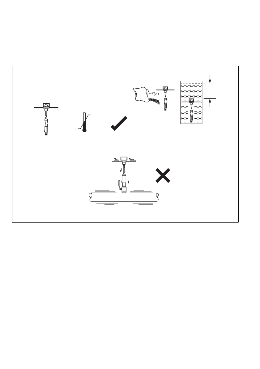
2.1 Location – Environmental Conditions ....................................................................................... 4
2.1.1 AquaProbe .................................................................................................................... 4
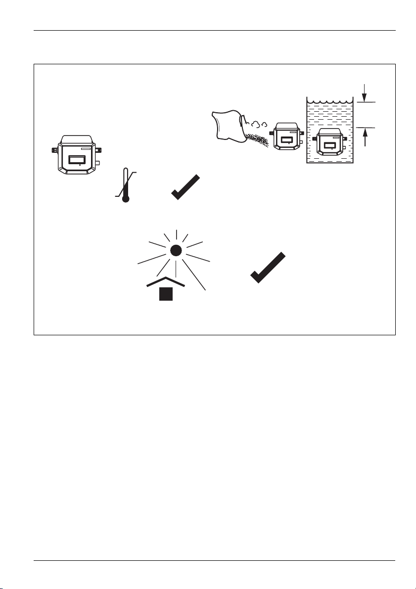
2.1.2 Transmitter .................................................................................................................... 5
2.2 Location – Flow Conditions ...................................................................................................... 6
2.2.1 International Standard for Flow Measurement ................................................................ 6
2.2.2 Velocity Limitations ........................................................................................................ 7
2.3 Location – Mechanical ............................................................................................................. 9
2.3.1 AquaProbe .................................................................................................................... 9
2.3.2 Transmitter .................................................................................................................. 10
2.4 Safety .................................................................................................................................... 11
2.5 Installing the AquaProbe ........................................................................................................ 12
2.6 Setting the Insertion Depth .................................................................................................... 13
2.6.1 Centre Line Method for Pipe Diameters ≤1m (≤40in ) ................................................... 13
2.6.2 Centre Line Method for Pipe Diameters >1m ≤2m (>40in ≤80in) .................................. 14
2.6.3 Mean Axial Velocity Method ......................................................................................... 15
2.7 AquaProbe Alignment ............................................................................................................ 16
3 Electrical Installation ..................................................................................................................... 17
3.1 Connections .......................................................................................................................... 17
3.1.1 Sensor Terminal Box Connections (Remote Versions only) .......................................... 17
3.1.2 Environmental Protection ............................................................................................. 18
3.1.3 Transmitter Connections ............................................................................................. 19
3.2 Input/Output Connections ..................................................................................................... 21
3.2.1 Frequency Outputs ...................................................................................................... 21
3.2.2 PLC Interface .............................................................................................................. 22
3.2.3 MIL Connector Input/Output Connections (Option) ...................................................... 23
3.2.4 Local Computer Connection ........................................................................................ 24
3.2.5 Remote Computer Connection (Option) ....................................................................... 25
3.2.6 Power Supply Connection Options .............................................................................. 26
3.2.7 Pressure Transducer (Optional) .................................................................................... 28
3.2.8 Environmental Protection (Option) ................................................................................ 29
4 Setting Up ...................................................................................................................................... 30
4.1 Introduction ........................................................................................................................... 30
4.2 Centre Line Method ............................................................................................................... 30
4.3 Mean Axial Velocity Method (1/8 Diameter) ............................................................................ 31
4.4 Partial Velocity Traverse ......................................................................................................... 31
4.5 AquaProbe Transmitter Setup ................................................................................................ 31

Insertion-Type Electromagnetic Probe Flowmeter
AquaProbe 2 Contents
2IM/AP Issue 9
5 Start Up And Operation ................................................................................................................. 32
5.1 Fitting the Battery ................................................................................................................... 32
5.2 Start-up ................................................................................................................................. 32
5.3 Display Activation ................................................................................................................... 33
5.4 Replacing the Battery ............................................................................................................. 34
Appendix A 35
A.1 Testing the Flow Profile for Symmetry .................................................................................... 35
A.1.1 Partial Velocity Traverse ............................................................................................... 35
A.1.2 Single Entry Point Method ............................................................................................ 35
A.1.3 Dual Entry Point Method .............................................................................................. 36
Appendix B Aquamaster Block Diagram ............................................................................................ 37
Notes .................................................................................................................................................. 38

Insertion-Type Electromagnetic Probe Flowmeter
AquaProbe 2 1 Introduction
IM/AP Issue 9 3
1 Introduction
The AquaProbe electromagnetic insertion flowmeter is designed for measurement of the velocity of water.
The flowmeter, available in four standard lengths, can be installed in any pipeline of internal diameter from
200mm (8in) to 8000mm (360in), through a small tapping.
The AquaProbe is designed for use in survey applications such as leakage monitoring and network analysis
and in permanent locations where cost or space limitations preclude the use of conventional closed pipe
meters.
1.1 System Schematic
Note.
The tip of the AquaProbe is a precision-built part of the equipment and must be handled with care.
When the AquaProbe is not in use, fully retract the tip of the probe and replace the end-cap.
When removing/inserting the probe into the pipeline, ensure that the valve is fully open.
Damage to the probe effects the performance.
Physical damage to the probe invalidates the warranty.
Fig. 1.1 System Schematic
Power
Output
Sensor
Potted
Connections
AquaMaster

Insertion-Type Electromagnetic Probe Flowmeter
AquaProbe 2 2 Mechanical Installation
4IM/AP Issue 9
2 Mechanical Installation
2.1 Location – Environmental Conditions
2.1.1 AquaProbe
Fig. 2.1 Environmental Requirements – AquaProbe
60°C (140°F)
Maximum.
–20°C (-4°F)
Minimum.
A – Within Temperature Limits
C – Avoid Excessive Vibration
10m
(30ft)
B – Within Environmental Rating
IP68 (NEMA 6)

Insertion-Type Electromagnetic Probe Flowmeter
AquaProbe 2 2 Mechanical Installation
IM/AP Issue 9 5
2.1.2 Transmitter
Fig. 2.2 Environmental Requirements – AquaMaster Transmitter
AquaMaster
-20°C (-4°F)
Minimum
60°C (140°F)
Maximum
A – Within Temperature Limits
C – Shade from Heat
AquaMaster
AquaMaster
1.5m
(60in)
IP68 (NEMA 6)
ENCLOSURE 6P
B – Within Environmental Rating

Insertion-Type Electromagnetic Probe Flowmeter
AquaProbe 2 2 Mechanical Installation
6IM/AP Issue 9
2.2 Location – Flow Conditions
The probe may be installed in one of two positions in the pipe; either on the centre line or at the mean axial
velocity point (1/8 pipe diameter). It may also be traversed across the pipe to determine the velocity profile.
2.2.1 International Standard for Flow Measurement
ISO 7145 '(BS 1042) Measurement of fluid flow in closed conduits' Part 2 'Velocity area methods'
describes methods of calculating volumetric flow from velocity measurements.
Section 2.2: 1982 'Method of measurement of velocity at one point of a conduit of circular cross section'
describes the inference of volumetric flow from measurement of velocity at a single point. Several
conditions must be fulfilled to validate the method, which uses calculations based on empirical data.
Where the validating conditions can be met, the method described in Section 2.2 is the most practical. It is
possible to measure the velocity either on the centre line, which reduces sensitivity to positional errors, or at
the assumed point of mean flow velocity.
Table 2.1 is an extract from ISO 7145 (BS 1042): Section 2.2: 1982 and is reproduced with the permission
of BSI. Complete copies of the standard can be obtained by post from BSI Publications, Linford Wood,
Milton Keynes, MK14 6LE.
Note. Ensure that the sensor is installed in the pipe with the flow direction arrow on the probe case
matching the pipe flow.
Fig. 2.3 Flow Conditions
Note. Where the above ideal conditions cannot be achieved, the flow profile must be tested for
symmetry in order to obtain reliable flow results.
5 Diameters See Table 2.1

Insertion-Type Electromagnetic Probe Flowmeter
AquaProbe 2 2 Mechanical Installation
IM/AP Issue 9 7
2.2.2 Velocity Limitations
All insertion probe devices are susceptible to the vortex shedding effect which can cause severe vibration of
the probe, resulting in damage and/or measurement instability. Electromagnetic devices with no moving
parts, such as AquaProbe, are less susceptible to this effect than mechanical devices.
The graphs below show the maximum permissible velocities, depending on the probe's location.
This information is provided as a guide only. Some installations may experience unwanted vibration
resonance which may further limit the maximum velocity at which the AquaProbe may be used.
Type of disturbance upstream from the
measuring cross-section
Minimum upstream straight length*
For a measurement at the
point of mean axial velocity
For a measurement on the
axis of the conduit
90° elbow or a t-bend
Several 90° coplanar bends
Several 90° non- coplanar bends
Total angle convergent 18 to 36°
Total angle divergent 14 to 28°
Fully opened butterfly valve
Fully opened plug valve
50
50
80
30
55
45
30
25
25
50
10
25
25
15
* Expressed in multiples of the diameter of the conduit.
Downstream from the measurement cross-section, the straight length shall be at least equal to five duct diameters
whatever the type of disturbance.
Table 2.1 Straight Pipe Lengths
Fig. 2.4 Maximum Permissible Velocity for different Pipe Sizes
Pipe Size in inches
Maximum Velocity in m/s
Pipe Size in mm
Maximum Velocity in ft/s
0
3.0
7.0
0200 400 600 800 1000 1200 1400 1600 1800 2000
0
1.0
2.0
3.0
4.0
5.0
6.0
816 24 32 40 48 56 64 72 80
10.0
13.0
17.0
20.0
Centre Line Method

Insertion-Type Electromagnetic Probe Flowmeter
AquaProbe 2 2 Mechanical Installation
8IM/AP Issue 9
Fig. 2.5 Maximum Permissible Velocity for different Pipe Sizes
Fig. 2.6 Maximum Permissible Velocity for different Insertion Lengths
Pipe Size in inches
Maximum Velocity in m/s
Maximum Velocity in ft/s
Pipe Size in mm
0 1000 2000 3000 4000 5000 6000 7000 8000
0
3.0
7.0
10.0
13.0
17.0
20.0
0
1.0
2.0
3.0
4.0
5.0
6.0
40 80 120 160 200 240 280 320
Mean Axial Velocity
Method (1/8Diameter)
Insertion Length in mm
Maximum Velocity in m/s
Maximum Velocity in ft/s
Insertion Length in inches
0
1.0
2.0
3.0
4.0
5.0
6.0
0
3.0
7.0
10.0
13.0
17.0
20.0
4 8 12 16 20 24 28 32 36 40
0 100 200 300 400 500 600 700 800 900 1000
Traversing

Insertion-Type Electromagnetic Probe Flowmeter
AquaProbe 2 2 Mechanical Installation
IM/AP Issue 9 9
2.3 Location – Mechanical
2.3.1 AquaProbe
Note. Pipeline recommended to be metal for electrical screening.
Fig. 2.7 Mechanical Requirements – AquaProbe
320mm (12.5in)
1in BSP
1.5in BSP
1in NPT
900, 1100, 1300, or 1600 mm
(36, 44, 52, or 63in)
B – Orientation
A – Clearance Dimensions
On Centre Line
On Centre Line

Insertion-Type Electromagnetic Probe Flowmeter
AquaProbe 2 2 Mechanical Installation
10 IM/AP Issue 9
2.3.2 Transmitter
Fig. 2.8 Clearance Dimensions – Transmitter
AquaMaster
170mm
(6.7in)
140mm
(5.5in)
Installation and
wiring access
300mm min.
450mm
preferred
Allowance for cable
bend
130mm (Standard)
200mm (Armoured)
Allowance for cable
bend
130mm (Standard)
200mm (Armoured)
146.0mm
125.0mm ø6.0mm
ø12mm
ø6.0mm
Transmitter Mounting Plate
Details
150
mm
Transmitter Mounting
Plate
170mm
(6.7in)
170
mm

Insertion-Type Electromagnetic Probe Flowmeter
AquaProbe 2 2 Mechanical Installation
IM/AP Issue 9 11
2.4 Safety
Warning. The Aquaprobe is provided with a safety mechanism (see Fig. 2.9A ) which should be
attached to its securing collar as shown in Fig. 2.9B. This prevents rapid outward movement by the
probe if the nut 1 is released.
Note. To ensure maximum safety, the positioning collar MUST be tightened in place using a 4mm
hexagon key
Fig. 2.9 Safety Mechanism
See Warning
A Unsecured B Secured
1

Insertion-Type Electromagnetic Probe Flowmeter
AquaProbe 2 2 Mechanical Installation
12 IM/AP Issue 9
2.5 Installing the AquaProbe
Warning. When inserting or removing the AquaProbe suitable restraining equipment must be used to
prevent the probe being forced out under pressure. Ensure that the valve is fully open.
Fig. 2.10 Insertion Bore Clearance
Fig. 2.11 Installing the AquaProbe
25mm (1in) Minimum
Clearance
Apply
PTFE Tape
Remove
Cap
Tighten
(hand tight only)
Insert Probe
Into Valve
Tighten
Firmly
1
3
4
5
2

Insertion-Type Electromagnetic Probe Flowmeter
AquaProbe 2 2 Mechanical Installation
IM/AP Issue 9 13
2.6 Setting the Insertion Depth
2.6.1 Centre Line Method for Pipe Diameters ≤1m (≤40in )
Warning. When inserting or removing the AquaProbe suitable restraining equipment must be used to
prevent the probe being forced out under pressure. Ensure that the valve is fully open.
Note. Safety restraint omitted for clarity.
Fig. 2.12 Setting the insertion Depth – Centre Line Method for Pipe Diameters 1m (40in)
1
2
9
Open Fully
Lower probe to
touch bottom
of pipe
Retract probe fully
Slide positioning collar
down to nut and lock
Slacken
ighten
to 40Nm
(30ft lbf)
Determine
internal
diameter
(D)
Unlock, slide
positioning collar
down and lock at distance: 30mm (1.181in)
30mm (1.181in)
D
2
D
2
Insert probe
to position
collar
depth
8
7
3
5
6
4
See Note

Insertion-Type Electromagnetic Probe Flowmeter
AquaProbe 2 2 Mechanical Installation
14 IM/AP Issue 9
2.6.2 Centre Line Method for Pipe Diameters >1m ≤2m (>40in ≤80in)
Warning. When inserting or removing the AquaProbe suitable restraining equipment must be used to
prevent the probe being forced out under pressure. Ensure that the valve is fully open.
Note. Safety restraint omitted for clarity.
Fig. 2.13 Setting the Insertion Depth – Centre Line Method for Pipe Diameters >1m 2m (>40in 80in)
Measure to top
of valve plate (VP)
Open Fully
Lower probe to
touch valve plate
Retract probe fully
Slide positioning collar
down to nut and lock
Slacken
ighten
to 40Nm
(30ft lbf)
Determine
internal diameter
(D)
Insert probe
to position
collar
depth
Unlock, slide positioning collar up and lock at distance:
D
2+ VP + 30mm (1.81in) + pipe thickness
1
9
82
4
7
7
6
5
10
3
See Note

Insertion-Type Electromagnetic Probe Flowmeter
AquaProbe 2 2 Mechanical Installation
IM/AP Issue 9 15
2.6.3 Mean Axial Velocity Method
Warning. When inserting or removing the AquaProbe suitable restraining equipment must be used to
prevent the probe being forced out under pressure. Ensure that the valve is fully open.
Note. Safety restraint omitted for clarity.
Fig. 2.14 Setting the Insertion Depth – Mean Axial Velocity Method
Measure to top
of valve plate (VP)
Determine
internal
diameter (D)
Open Fully
Lower probe to
touch valve plate
Retract probe fully
Slide positioning collar
down to nut and lock
Slacken
ighten
to 40Nm
(30ft lbf)
Insert probe to
position collar depth
D
8
Unlock, slide positioning collar up and lock at distance:
+ VP + 30mm (1.181in) + pipe thickness
7
76
5
3
10
4
82
9
1
See Note

Insertion-Type Electromagnetic Probe Flowmeter
AquaProbe 2 2 Mechanical Installation
16 IM/AP Issue 9
2.7 AquaProbe Alignment
Warning. When inserting or removing the AquaProbe suitable restraining equipment must be used to
prevent the probe being forced out under pressure. Ensure that the valve is fully open.
Note. Safety restraint omitted for clarity.
Note. Measurement error due to misalignment (of <2) is <0.15%.
Fig. 2.15 Probe Alignment
Align parallel to pipe
(within 2°) see Notes
Slacken
ighten
40Nm
(30ft lbf)
1
3
2
See Notes

Insertion-Type Electromagnetic Probe Flowmeter
AquaProbe 2 3 Electrical Installation
IM/AP Issue 9 17
3 Electrical Installation
3.1 Connections
3.1.1 Sensor Terminal Box Connections (Remote Versions only)
Caution. (Remote versions)
Make connections only as shown.
Remove foil screens
Twist the three screen wires together and sleeve them.
Twist cable pairs together
Maintain Environmental Protection at all times.
Conduit connections must provide cable entry sealing.
Fig. 3.1 Sensor Terminal Box Connections (Remote Version)
Caution. With Belden Cable 8777, ensure that the black wires are not interchanged, and remain with
the associated twisted pair.
CABLE
ABB Belden 8777
Violet White
Blue Black
Green Sleeved Ground
Yellow Red
Orange Black
Red Green
Brown Black
Maximum Cable Lengths
≤250 m ≤80 m

Insertion-Type Electromagnetic Probe Flowmeter
AquaProbe 2 3 Electrical Installation
18 IM/AP Issue 9
3.1.2 Environmental Protection
Fig. 3.2 Potting the Terminal Box
Warning.
Potting materials are toxic – use suitable safety precautions.
Read the manufacturers instructions carefully before preparing the potting material.
The remote sensor terminal box connections must be potted immediately on completion to
prevent the ingress of moisture.
Check all connections before potting – see section 3, page 17.
Do not overfill or allow the potting material to come into contact with 'O' rings or grooves.
Do not let potting material enter conduit, if used.
Table of contents
Other ABB Measuring Instrument manuals

ABB
ABB SensyMaster FMT430 User manual

ABB
ABB FSM4000 Series User manual

ABB
ABB ControlMaster CM15 User manual

ABB
ABB GLA131 Series User manual

ABB
ABB Sensyflow iG User manual

ABB
ABB GLA232 Series User manual

ABB
ABB Endura AZ20 series User manual

ABB
ABB Navigator 550 User manual

ABB
ABB BAMU-12C User manual

ABB
ABB FMT200-ECO2 User manual

ABB
ABB EL3000 Series User manual

ABB
ABB Stanilite Nexus LX User manual

ABB
ABB CoriolisMaster FCHB400 User manual

ABB
ABB FPD350 Torbar User manual

ABB
ABB Comem OLI User manual

ABB
ABB AquaMaster IM9 User manual

ABB
ABB AX413 User manual

ABB
ABB AX411 User manual

ABB
ABB M1M 30 Series User manual

ABB
ABB ProcessMaster FEP630 series User manual