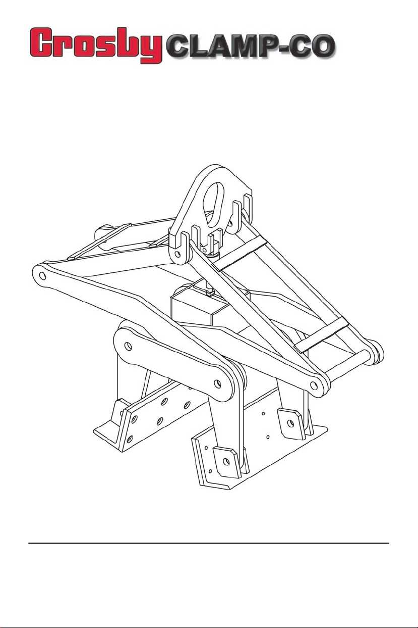
Crosby Clamp-Co BG-9000 User manual
IMPORTANT
Make certain all persons that may use, inspect, or maintain this equipment carefully read
and understand this manual. Retain this manual in a permanent file.
BARRIER GRAB CLAMP
USERS MANUAL
Model Numbers:
BG-9000
Barrier_Grab_Clamp_manual.fm Page 1 Thursday, May 28, 2009 3:10 PM

2 Copyright® 2009 The Crosby Group, Inc.
All Rights Reserved
INTRODUCTION
Crosby CLAMP-CO barrier grab (clamps) are below the hook lifting devices designed to
provide an efficient method for handling concrete road barriers. Always follow the stated
limitations discussed in this manual and shown on the products Warning and Operating
Procedure Labels.
Crosby Clamp-Co barrier grabs have been safely and successfully used in the field for
years. Your safe use of our products depends on you. Please be responsible and make
sure all people using our products follow these simple rules.
1. Barrier Grab (clamp) are used to the purpose for which they were designed.
2. They are not loaded beyond their Working Load Limit.
3. They are properly lubricated and maintained.
4. They are inspected regularly and tested in accordance with the relevant statutory
regulations.
5. They are used by competent persons trained in their use.
6. Barrier Grabs are returned to the factory every two years for inspection
retesting and recertification.
As with all mechanical handling equipment, there is a degree of hazard involved with the
use of these beam clamps if not properly used. Failure to follow the appropriate safety
precautions and operating instructions may cause the load to slip or fall, and may result in
serious injury, death, or property damage.
GENERAL INFORMATION
Each Crosby Clamp-Co barrier grab is proof tested and certified prior to shipping. Barrier
garb clamps are proof tested to 200% of Working Load Limit, unless specified otherwise
(See pages 6 & 7).
Follow all requirements of laws, rules, and regulations applicable in your country pertaining
to lifting operations, ensuring all maintenance, testing, inspection and operator training
requirements are strictly adhered to.
All Sizes are RFID EQUIPPED.
Barrier_Grab_Clamp_manual.fm Page 2 Thursday, May 28, 2009 3:10 PM

Copyright© 2009 The Crosby Group 3
All Rights Reserved
PRODUCT WARNING
WARNING
• Loads may disengage from clamp if proper procedures are not followed.
• A falling load may cause serious injury or death.
• The clamp shall not be loaded in excess of its rated load or handle any load for
which it is not designed.
• Never operate a damaged or malfunctioning clamp, or a clamp with missing
parts.
• Clamp not to be used for personnel hoisting.
• Do not carry a load over people.
• Do not leave suspended loads unattended.
• Operator and other personnel shall stay clear of the load.
• Never put your fingers, hand, arm, or a board, pipe or any object into the
mechanics of the barrier grab in an attempt to manually index the barrier grab.
• Do not lift loads higher than necessary.
• Do not make alterations or modifications to clamp.
• Do not remove or obscure warning or operating procedure labels.
• See ANSI/ASME B-30.20 BELOW-THE-HOOK LIFTING DEVICES for additional
information.
• LIFTING HEIGHT LIMITATION - This clamp is intended to be used to lift the
lowest part of the clamp to a height less than 6 feet or (1.8 m). NEN-EN 13155
requires a secondary positive holding device (e.g., sling, net, cage) for lifts
exceeding 6 feet or (1.8 m).
• Read, understand, and follow these instructions and the product safety
information.
Barrier_Grab_Clamp_manual.fm Page 3 Thursday, May 28, 2009 3:10 PM

4 Copyright® 2009 The Crosby Group, Inc.
All Rights Reserved
OPERATING PROCEDURES
• Perform regular DAILY inspections as recommended.
• Reference page 7 of this manual for Grip Width and Working Load Limitations.
• Barrier must be on level ground in it’s upright position. Do not use barrier grab to
rotate barrier from a horizontal position to vertical.
• Barrier grab must be free to move, not frozen to the ground or encumbered by other
barriers or debris.
• Make sure clamp is centered on concrete barrier and tongs are totally engaged.
• To ensure a proper grip on the barrier there must not be dirt, moisture, ice, grease,
scale, paint or other substance that will impede the grip of the barrier grip pads onto
the barrier. If sliding of the pads on the barrier occur, stop lift immediately.
• The grip on the barrier is totally dependant upon continuous and constant tension on
the lifting sling or hoist line. Do not allow tension to be relaxed during the lift by
inadvertently touching the ground, an object, or bouncing the barrier while it is being
lifted or carried over rough terrain.
• Use single (one) barrier grab in vertical lifting only, do not use in side loading
applications. Do not use barrier grab to drag or pull the barriers.
• The Crosby Clamp-Co barrier grab is not designed to be used in tandem with another
grab through use of a double leg sling, spreader beam, or other equipment.
• Temperature and environment: The temperature at which the standard lifting clamps
may be used lies between 160° F (71° C) and -40° F (-40° C). For other temperatures
and for use in hazardous environmental conditions, consult The Crosby Group, Inc.
technicians.
Barrier_Grab_Clamp_manual.fm Page 4 Thursday, May 28, 2009 3:10 PM
Copyright© 2009 The Crosby Group 5
All Rights Reserved
USING THE BARRIER GRAB CLAMP
The barrier grab is designed to automatically index to an open position or a gripping
position as required by following a simple procedure. Occasionally the barrier grab may tip
to one side or not index properly. In this event do not manually index the barrier grab, but
instead lower the barrier grab back onto the barrier and repeat the process following the
proper procedure. Never put your fingers, hand, arm, or a board, pipe or any object into the
mechanics of the barrier grab in an attempt to manually index. If barrier grab does not
index properly after repeating the process, remove from service and reference the
inspection and maintenance section of this manual. Do not attempt to repair a damaged
clamp by welding or with unauthorized replacement parts. We recommend returning the
clamp to the manufacture.
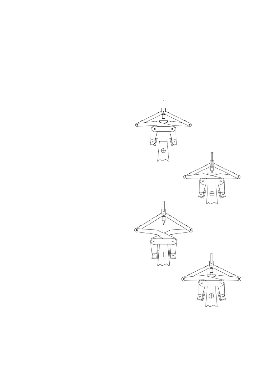
With the grab indexed to the open position,
slowly lower the grab onto the barrier and
center the grab in-line with the barrier’s
center of gravity. (See Figure 1).
Slowly release tension on the lifting cable
until the grab is completely relaxed on top
of the barrier (See Figure 2).
Slowly pick up on the lifting cable. The grab
will automatically index to the gripping
position. Grip pads will compress against
the sides of the barrier. Continue to lift barrier,
keeping lifting cable in tension (See Figure 3).
In the event the grab does not automatically
index to the gripping position, repeat above
process. Never put your fingers, hand, arm,
or a board, pipe or any object into the
mechanics of the barrier grab in an attempt
to manually index .
After placement of barrier, continue to release
tension on the lifting cable until it is fully
relaxed. This will allow the grab to index to
the open position (See Figure 4).
The barrier grab can now be lifted
away from barrier.
Figure 1
Figure 2
Figure 3
Figure 4
Barrier_Grab_Clamp_manual.fm Page 5 Thursday, May 28, 2009 3:10 PM
6 Copyright® 2009 The Crosby Group, Inc.
All Rights Reserved
INSPECTION AND MAINTENANCE
A visual inspection for cracks, wear, gouges and deformation as part of a comprehensive
documented inspection program should be conducted by trained personnel in compliance
with the schedule in ANSI B30.20. Proper maintenance of the barrier clamp includes a
daily inspection and weekly lubrication. There are labels attached to the clamp frame
which provides required maintenance, inspection and lubrication recommendations.
Product labels should be replaced when they are no longer legible. You should contact The
Crosby Group for replacement labels.
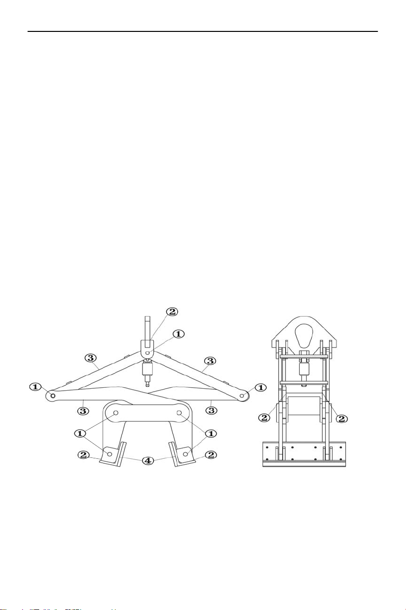
• Inspect pin welds for cracks or signs of failure. (1)
• Inspect all load carrying welds for cracks or signs of failure. (2)
• Inspect metal arms and linkage to determine if they are bent or warped (3)
• Grip pads must be securely bolted onto the barrier grab and be free from wear.
Replace with genuine Crosby Clamp-Co polyurethane grip pads. (4)
• If provided with hardened steel pads, rather than polyurethane, check for wear and
replace if worn. Replace with genuine Crosby Clamp-Co hardened steel grip pads.
• Lubricate index pin assembly, load pins and moving parts with oil can or spray at least
once a week.
INSPECTION AND LUBRICATION POINTS
Do not attempt to repair a damaged clamp by welding or with unauthorized replacement
parts. We recommend returning the clamp to the manufacturer when repairs are required.
Barrier_Grab_Clamp_manual.fm Page 6 Thursday, May 28, 2009 3:10 PM
Copyright© 2009 The Crosby Group 7
All Rights Reserved
INSPECTION AND MAINTENANCE CHECK LIST
• Is any part of the equipment distorted?
• Are any cracks visible, or is extensive corrosion evident?
• Is there wear evident at suspension points, shackles, master link, pivots, pins, bolts,
threads, or other moving and / or load bearing parts?
• Are the Working Load Limit, Serial Numbers and Warning labels legible?
• Have all inspections and maintenance been regularly recorded?
• Does the Crosby Clamp-Co product carry its original Identification Plate and Warning
Information?
• If the identification plate has been damaged or removed, the clamp shall be taken out
of service and arrangements made to replace the identification plate.
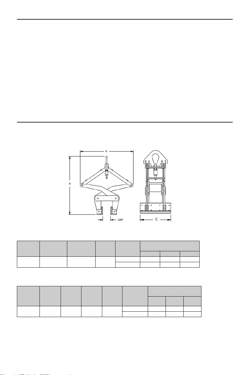
BARRIER GRAB MODEL BG 9000
Concrete barriers selected to lift must be within the limits of recommended Grip Width and
Working Load Limit as shown in Figure 2.
Figure 2
Barrier Grab - Imperial
Barrier Grab - Metric
The above information is for standard size clamp models. For special clamp models not
located in table, please refer to I.D. tag affixed to product for proper Working Load Limit
and size limitations.
Model
No.
CCBG-150
Stock
No.
Working
Load Limit
(Tons)
Weight
Each
(lbs.)
Grip
Width
(in.)
Dimensions
(in.)
A B C
BG-9000 2734009 4.5 290 6 (min.) 40.88 44.88 18.00
12 (max.) 44.00 36.75 18.00
Type
Model
No.
CCBG-
150
Stock
No.
Working
Load
Limit
(t)
Weight
Each
(kg.)
Grip
Width
(mm)
Dimensions
(mm)
A B C
Barrier
Grab BG-9000 2734009 4.08 132 152 (min.) 1038 1140 457
305 (max.) 1118 934 457
Barrier_Grab_Clamp_manual.fm Page 7 Thursday, May 28, 2009 3:10 PM

Copyright® 2009 The Crosby Group, Inc.
All Rights Reserved
P.O. Box 3128 Tulsa, Oklahoma 74101
(918) 834-4611
www.thecrosbygroup.com
stock # 9999277
Barrier_Grab_Clamp_manual.fm Page 8 Thursday, May 28, 2009 3:10 PM
Table of contents
Other Crosby Industrial Equipment manuals


