9INM F300 rev 6
DRAFT- 09 July 2019 DRAFT- 09 July 2019
9 FM CONTROL DRAWINGS
FIELDBUS POWER SUPPLY
Vout (max) ≤24V Gas Groups A, B (IIC)
Vout (max) ≤32V Gas Groups C,D (IIB, IIA)
Iout (max) ≤2A
Must meet Ex n requirements for
Ex nA [nL] installations.
+
S
-
+
S
-
+ -
24VDC Power
Source (typical)
Host Connection (typical)
NON-HAZARDOUS LOCATION
Shield is grounded for reasons other than Electrical Safety
Class I Div 2 ABCD T4 -50°C ≤Tamb ≤70°C
Class I Zone 2 IIC T4 (US only)
Ex nA [nL] IIC T4 (Canada only) Field wiring shall be rated for 70C
HAZARDOUS (CLASSIFIED) LOCATION
Black Trunk
Connections
Gray Spur Outputs are energy limited (Non-
incendive Field Wiring) and may be live worked
without gas clearance where allowed by local
code.
To support live working of the devices
connected to the gray spurs, the following
criteria must be met:
Device must have entity parameters with
a maximum input voltage greater than or
equal to Voc of the Megablock.
Ca≤Ci+ Ccable
La≤Li+ Lcable
F3xx Megablock
Terminator
F97
Vmax=32V
Imax = 2A
+S-
Megablock™ Part Numbers:
F3xx[-V2][-T][-PC][-PD]
xx – indicates the number of spurs (04, 08, 12, or 16)
-V2 – option for no over-voltage protection
-T – option for a built-in terminator
-PC – option for pluggable spring clamp connectors
-PD – option for pluggable insulation displacement
connectors
Standard connectors are Pluggable Screw Terminal type.
The F97 is not used if the F3xx contains an internal
Terminator (-T part number suffix).
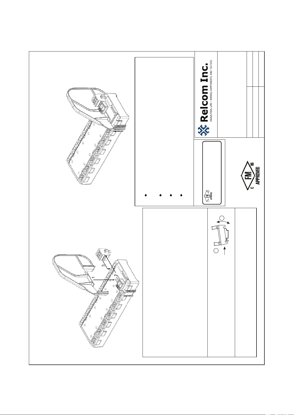
FM CONTROL DRAWING FOR F3XX
MEGABLOCK™ SERIES FIELDBUS
CONNECTION BLOCKS
CID2, Zone 2 INSTALLATIONS
Doc. No. 502-484 Rev. C.0
Sheet 1 of 2
2221 Yew Street, Forest Grove, Oregon 97116 USA
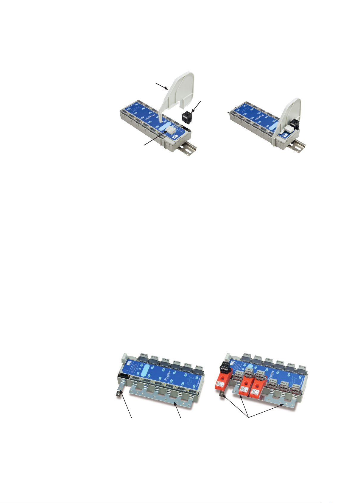
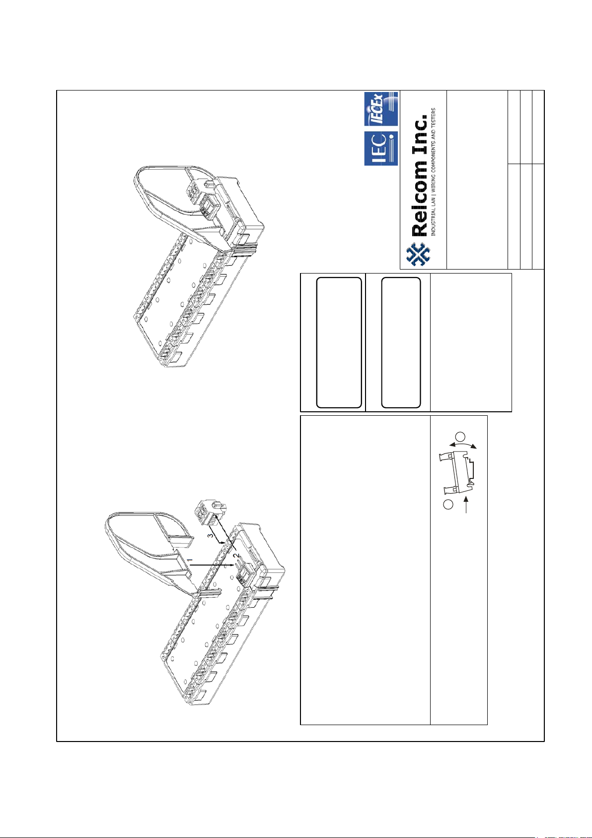
F3xx Megablock™
Fieldbus Connection Block
(F308, 8-spur series shown)
Gray spur connections are
Current limited to 53.5mA (nominal)
Vmax= 24V Gas Groups A, B (IIC)
Vmax= 32V Gas Groups C, D (IIB, IIA)
Imax = 2A
Voc = Vmax power supply
Isc = 56mA
Ci= Li= 0,
Po= 1.344W Gas Groups A, B (IIC)
Po= 1.792W Gas Groups C, D (IIB, IIA)
+
S
-+
S
- +
S
- +
S
-
+
S
-+
S
- +
S
- +
S
-
+S-
+S-
Fusing of the power
source is recommended
If the Fieldbus Power Supply is suitably rated, it may be installed in the Hazardous Area.
Installation must be in accordance with the National Electrical Code
(NFPA 70, Article 504), ANSI/ISA-RP12.6, and CEC Part 1, or any
other applicable local electrical requirements.
The plastic parts can store static charge. Clean only with a damp
cloth to prevent static buildup.
Wire Requirements:
Connector Type AWG Torque
Screw Terminal 22-14 0.5-0.6Nm
Spring Clamp 24-12 NA
Insulation Displacement 20-18 NA
WARNING – EXPLOSION HAZARD. DO NOT DISCONNECT EQUIPMENT WHEN
A FLAMMABLE OR COMBUSTIBLE ATMOSPHERE IS PRESENT
(except gray spurs)
Gas Groups A, B (IIC) C (IIB) D (IIA)
Ca 80nF 80nF 80nF
La 0.15mH 0.26mH 0.26mH
Galvanic isolation in accordance with IEC61010 provided by Power Source or Power Supply.
Approved by: Cyrus Kelly Date: 10 FEB 2017
Gray Spur (Fieldbus Device) Connections
Gray Spur (Fieldbus Device) Connections