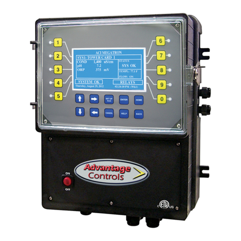
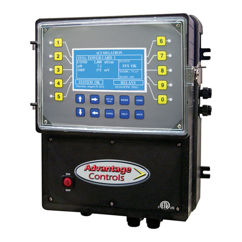
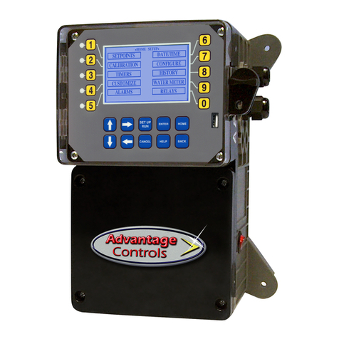
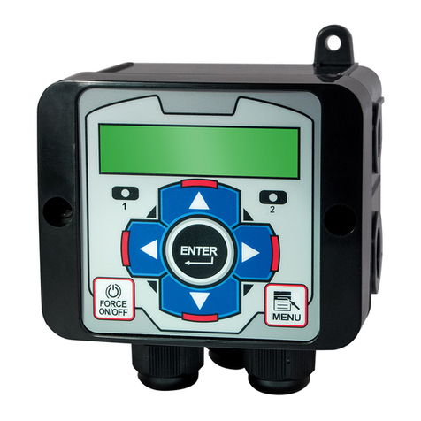
Advantage Controls MegaTronMT User manual

1
Manual
Touch Screen
Controller
Installation
Maintenance
Repair
Manual
Advantage Controls
P.O. Box 1472
Muskogee, OK 74402
Phone: 918-686-6211
Fax: 918-686-6212
www.advantagecontrols.com
email: [email protected]
12/2018

2
MegaTronMT Touch Screen Controller
Instruction & Maintenance Manual
Table of Contents
Contents Page
I. Introduction ................................................................................. 3
Model Numbering ....................................................................... 3
Description of Unit ...................................................................... 3
II. Installation .................................................................................. 4
Electrical Wiring .......................................................................... 4
Wiring Diagrams ......................................................................... 5
Mounting Instructions ................................................................. 8
Electrode Installation .................................................................. 8
A. Cooling Tower ....................................................................... 8
B. Boiler ................................................................................... 10
III. Front Panel ............................................................................... 12
IV System Operation Overview ..................................................... 13
Start-Up .................................................................................... 13
Calibration ................................................................................ 13
V. Menu Navigation....................................................................... 14
VI. Maintenance ............................................................................. 31
Electrode Cleaning Procedures ................................................ 31
VII. Troubleshooting ........................................................................ 32
VIII. Warranty & 30 Day Billing Memo Policy ................................... 33
Additional Wiring Diagrams ...................................................................... 34

3
I. Introduction
The MegaTronMT microprocessor-based controllers are programmable through a front panel touch screen
DQGFDQEHFRQ¿JXUHGWRFRQWURODZLGHUDQJHRIGLJLWDODQGDQDORJLQSXWV<RXUSDUWLFXODUXQLW¶VIXQFWLRQVFDQ
be determined by comparing the units model number to the Model Numbering table listed below.
Model Numbering
0HJD7URQ07XQLWVKDYHVHYHUDOEDVHV\VWHPFRQWUROIXQFWLRQVDQGXQLWRSWLRQDOIHDWXUHV<RXUXQLWPD\EH
supplied with one or more of the features described in this manual. To determine what features apply to your
unit check the model number label located on the controller enclosure.
Base System Control Functions
C - Tower Conductivity Control
B2 - Boiler No Temp Conductivity
M - Make-up / Misc Conductivity
P - pH Control
R - ORP Control
T - Temp probe
F1 to F5- Chemical Feed Timers
E - Flow Switch
Whole Unit Optional Features
A - Conduit Connections (115 VAC)
A3 - Liquid tights only for (220-240 VAC)
H11 - Internet card with CAT5 & BACNet TCP/IP
H21 - Internet card with CAT5 & BACNet TCP/IP
N - 4-20mA input (N4 or N8)
O - 4-20mA outputs (O4 or O8)
S - pH Saturation indexes
V - 5 volt D.C. output with water meter wires
W - Auxiliary Flow Meter Inputs, 10 inputs
Y - ETL Agency Listing / Approvals
Model numbers start MT followed by the System Control functions. A dash separates the whole unit options
listed after all base system control functions. Example: MTCPF3E-N4.
1RWLFH<RXUXQLWPD\QRWKDYHDOOIHDWXUHVDQGIXQFWLRQVGHVFULEHGLQWKLVPDQXDO7KLVOLVWUHSUHVHQWVRXU
most popular options, additional option codes are available. Consult representative for more details.
Description of Unit
MegaTronMT controllers can control single or multiple recirculating water systems, including cooling tower
and boiler applications, and may have various features depending on the model number.
Control Functions
Each of these control functions are based on an analog input from a probe and will include user settable relay
control settings along with a High and Low Alarm setting and Limit Timer. Each control function will include a
control relay output. When the reading reaches the Set Point the control relay is activated until the reading
FKDQJHVE\WKH'LႇHUHQWLDODPRXQW
1. System Conductivity - The conductivity function of the controller is designed to monitor and
control Total Dissolved Solids (TDS) in a recirculating system like a cooling tower or boiler in terms
of electrical conductivity measured in MicroSiemens/cm. This control function is also referred to
as Bleed.
2. Make-up or Miscellaneous Conductivity -This conductivity with the probe installed in the fresh
make-up water line can be used to control the conductivity of the tower in terms of cycles of
FRQFHQWUDWLRQ E\ FDOFXODWLQJ WKH GLႇHUHQFH EHWZHHQ WKH PDNHXS ZDWHU¶V FRQGXFWLYLW\ DQG WKH
V\VWHP¶VFRQGXFWLYLW\ ,WFDQDOVREHXVHG WRPRQLWRUDQRWKHUFRQGXFWLYLW\ZLWKQRIHHGWLPHUV
associated with it.
3. pH - The pH function monitors and controls pH on a scale of 0-14 pH units.
4. ORP - The ORP function monitors and controls ORP on a scale of +/- 1000 mV.

4
Chemical Feed Timers
Chemical feed timers are designed to automate the addition of various chemicals by activating a relay output.
Multiple timers can be supplied depending upon the model number and each timer will include a relay output.
All timers can be programmed to be one of the following types.
1. Pulse Time - Accepts pulses from a make-up water meter (supplied separately). It can accumulate
1-9999 gallons before activating the timer to run.
2. Feed with Bleed - Activates the relay output simultaneously with the bleed and limits the amount
of time the relay output will be on during the bleed cycle.
3. Feed after Bleed$FWLYDWHVWKHUHOD\RXWSXWEDVHGRQDXVHUGH¿QHGSHUFHQWDJHRIWLPHEDVHG
RQWKHEOHHGRႇDQRWKHUWLPHURUGLJLWDOLQSXW7KHUHOD\LVDFWLYDWHGDIWHUDEOHHGF\FOHDQGUXQV
for the set percentage of that bleed cycle.
4. Recycle7KHUHOD\LVFRQWLQXRXVO\UHSHDWLQJDGH¿QHG2))F\FOHWLPHDQGDXVHUGH¿QHG21
cycle time.
5. 28 Day - The timer is based on a 28 day cycle with four independent programmable feed cycles
with prebleed and bleed lockout settings.
II. Installation
Electrical Wiring
7KH0HJD7URQ07FRQWUROOHUKDVDQLQWHUQDOUHJXODWHGIXVHGSRZHUVXSSO\WKDWZLOORSHUDWHRႇRIWR
VAC at 47 to 63 Hz on the incoming wiring. Each output relay is individually protected with a replaceable fuse.
Relay outputs will equal incoming line voltage.
WARNINGS:
1. The controller should be connected to its own isolated circuit breaker, and for best
results, the ground should be a true earth ground, not shared. Wiring must be done
according to all applicable local codes.
2. Power (line voltage) must be disconnected while making any connections. If power is
supplied to the unit, line voltage will be present on the relay cards located in the
ORZHUVHFWLRQRIWKHHQFORVXUHHYHQZLWKWKHSRZHU212))VZLWFKRႇ
/RZYROWDJHVLJQDOZLUHVSUREHVÀRZVZLWFKZDWHUPHWHUHWFVKRXOGQHYHUEHUXQ
in conduit with high voltage (like 115VAC) wires.
4. Units should be ordered with the appropriate option to provide powered relays designed for the
incoming/outgoing power.
127( /LTXLGWLJKW¿WWLQJVDQGVRPHODEHOHGVLJQDOOHDGVDUHSURYLGHGIRUDOOVLJQDO
(low voltage) connections for both pre-wired and conduit units.
!

5
Pre-Wired
Pre-wired units are supplied with a 16 AWG cable(s) with 3-wire grounded USA 115 volt plug for incoming
power and 3-wire grounded receptacle cords for all control relay outputs also 16 AWG.
Conduit
Conduit units are predrilled at the factory and supplied with conduit knockouts for easy hard wiring to supplied
detachable connectors on the relay card(s) located in the lower section of the controller. Remove the screws
of the lower panel for access.
NOTES:
1. Do not drill holes in upper section of enclosure.
2. All relays provide a N.O. and N.C. output.
7KHFRQWUROIXQFWLRQWKDWDFWLYDWHVHDFKUHOD\RXWSXWLVSUHFRQ¿JXUHGDWWKHIDFWRU\
based on the options selected. To change relay activation, see on page 30.
4. See page 34 for common bleed / blowdown valve wiring.
5HIHUWRODEHOLQVLGHORZHUSDQHOFRYHUIRUVSHFL¿FUHOD\ERDUGFRQ¿JXUDWLRQVXSSOLHG
5HOD\VFRQ¿JXUHGDV³GU\FRQWDFW´VKRXOGRQO\KDYH'&YROWDJHUDQWKURXJKWKHP7KH*1'
FRQQHFWLRQSRLQWUHSODFHVWKH1(8ZKHQFRQ¿JXUHGIRUGU\FRQWDFW([DPSOH8VH*1'DQG12
for a normally open dry contact relay output.)
WARNING:,IMXPSHUVDUHQRWFRQ¿JXUHGIRUGU\FRQWDFWOLQHYROWDJHZLOOEHVXSSOLHG
Relay Card Wiring
Rev. I Relay Card
!
Powered relay Dry contact
INPUT

6
Back Pane Connections
MT Megatron Main, Rev. B
Card Slots
1234567
(H11, H12)
Comm.
Relay Card Outputs
16-2011-15
6-10
1-5
Incoming
Power
GND
MegaTronMT Back Pane
+12 VDC
for paddlewheel
owmeters
Display Interface
Power to display
Gnd
Gnd
-12
-12
+12
+12
+5
+5
Jumper Block
Spare Power
System Card Connections
LED
Red
Black
Green
White
Ground
Drum Level 5
Drum Level 4
Drum Level 3
Ground
Drum Level 2
Drum Level 1
Water Meter Ground
Water Meter 2 Signal
Water Meter 1 Signal
Flow Switch
Black
Red
Red
Black
Standard System Card
ORP
ORP
pH
pH
Note: Use 22 AWG
(.76 mm) twisted
pair shielded wire
for all of these low
voltage signal
connections.
System Conductivity
Temperature
Note: Conductivity
probe’s wire colors
may vary. If so,
match based on
cond and temp.
White
Black
6 conductors plus a
shield must be ran
from the controller
to the probe. Connect
the 4 wires for the
temperature at the
terminal block
supplied with
the sensor
as shown.
Red
Green
Orange
Blue
White
Black
Red
Green

7
4-20mA Output Card Wiring
$ ,VRODWHG&RQ¿JXUDWLRQ
For isolated 4-20mA outputs an external power source for the loop must be supplied. JP4 and JP5 on the
board must be jumpered for isolated with an external power source supplied to the external VDC input. The
external power source must not exceed 24 volts DC.
% 1RQLVRODWHG&RQ¿JXUDWLRQ
For non-isolated 4-20mA outputs the controller will supply the power for the loop. JP4 and JP5 must be
jumpered for non-isolated and no connections are made to the external VDC points.
Note: If multiple outputs are being connected to a single energy management system the negatives or commons
MUST remain isolated from each other.
4-20mA Input Card Wiring
The 4-20mA input card requires that the external device sending the 4-20mA input signal(s) supply the power
for the loop. The external power source must not exceed 24 volts DC.
IN1+
V+
V+
V+
V-
V-
V-
VEXT+
VEXT-
01+
01-
02+
02-
03+
03-
04+
04-
ISO
LED
ISO ISO ISO
IN1-
IN2+
IN2-
IN3+
IN3-
IN4+
IN4-
J5
J4
mA Outputs are supplied
as non-isolated as shown.
For isolated outputs
J4 and J5 jumpers
must be congured
as shown to here.
ISO
External
VDC Input
J8
J6
If J4 and J5 are set for isolated an
external DC voltage must be
connected to power the mA
outputs.
If J8 & J6 and set for isolated as
shown istead of the standard non-
isolated the external VDC will be
applied to the other V- and V+
connection points instead of
the controller’s internal 12 VDC
on the V+ and ground on the
V- connections.
ISO
mA
Inputs
1-4
mA
Outputs
1-4
DC
Voltage
Connections

8
Mounting Instructions
Select a mounting location that provides the operator easy access to the unit and a clear view of the
controls through the cover of the controller. The location should be convenient to grounded electrical
connections, the needed sample line plumbing, and should be on a stable vertical surface.
WARNING: Avoid locations that expose the controller to direct sunlight, vapors, vibration,
liquid spills or extreme temperatures; less than 0°F (-17.8°C) or greater than 120°F (50°C). EMI
(electromagnetic interference) from radio transmissions and electric motors can also cause damage
or interference and should be avoided.
Electrode Installation
0HJD7URQ07FRQWUROOHUVPD\FRPHFRQ¿JXUHGIRUYDULRXVFLUFXODWLQJZDWHUV\VWHPV/LVWHGEHORZDUH
LQVWUXFWLRQVIRUW\SLFDOFRROLQJWRZHUDQGERLOHULQVWDOODWLRQV<RXUVSHFL¿FLQVWDOODWLRQUHTXLUHPHQWVPD\
GLႇHUEXWVKRXOGFRQIRUPWRWKHVHLQVWUXFWLRQVDVPXFKDVSRVVLEOHIRUSURSHURSHUDWLRQ
A. Cooling Tower
7KHVWDQGDUGSUREHVDQGRUÀRZDVVHPEO\IRUFRROLQJWRZHULQVWDOODWLRQVLVFRQVWUXFWHGRIVFKHGXOH
39&DQGVXSSOLHGZLWKñ»´VOLS¿WWLQJVIRULQVWDOOLQJLQWRDVDPSOHOLQH7RLQVXUHSURSHURSHUDWLRQWKH
VDPSOHOLQHPXVWKDYHDÀRZUDWHRIJSP,QOHWSUHVVXUHPXVWEHKLJKHUWKDQRXWOHWSUHVVXUHLQ
RUGHUIRUZDWHUWRÀRZSDVWWKHHOHFWURGHVWRDFKLHYHWKHUHTXLUHGUDWH7KHSUREHVDUHWHPSHUDWXUH
compensated for increased accuracy.
NOTES:
,QVWDOODQLVRODWLRQYDOYHRQHLWKHUVLGHRIWKHÀRZDVVHPEO\VRHOHFWURGHVFDQEH
easily isolated for removal and cleaning.
2. A line strainer is recommended upstream from the probes to protect against fouling
and damage.
3. Mount pH or ORP electrodes vertically.
4. Green solution reference wire must be connected to either pH or ORP sensor. If both
pH & ORP are present on system card, only one solution reference connection is
needed.
6\VWHPVZLWKDÀRZVZLWFKUHTXLUHJSPÀRZUDWHWRRSHUDWHRXWSXWV
WARNINGS:
1. Electrodes are O-ring sealed, which if damaged will cause a leak.
2. Do not allow pH sensor tips to dry out, damage will occur.
3. Do not exceed a water temperature range of 32°F to 140°F.
4. Do not exceed a maximum pressure of 125 psi.

9
Typical Cooling Tower Installation Diagram
COOLING TOWER
CIRCULATION PUMP CHILLER
BLEED VALVE
TO DRAIN
BLOWDOWN
MAKE-UP
WATERMETER
Cooling Tower Probe Assembly
Standard Tower Probes
Conductivity ...................E-4A
pH ..................................PE-2
ORP .............................. OE-2
FS-0C
FS-FC
FS-SP
-or-
PE-21
OE-21
PE-NUT
pH Probe
ORP Probe
OR
FS-T
TFS-OC
TFS-C
FS-B1-SP
SampleValve
E-30-PH 2C0A-150
UNION-3/4TT
FS-PT-P
Paddle Flow Switch
used with option
E3
E-30-PH
1A9A000262

10
B. Boiler
Standard boiler electrodes have a MNPT stainless steel bushing and are supplied with a FNPT cross
GHVLJQHGIRUPRXQWLQJLQWKHVNLPPHUVXUIDFHEORZGRZQOLQH6DPSOLQJRIWKHERLOHU¶VZDWHUFDQEH
DFKLHYHGXVLQJRQHRIWZRW\SLFDOSOXPELQJFRQ¿JXUDWLRQVFRQWLQXRXVVDPSOLQJRUWLPHGDQGRUVDPSOH
& hold). For a successful installation, it is critical to observe the recommended distances and pipe sizes
provided in the installation drawings.
)RUEHVWUHVXOWVWKHHOHFWURGHFURVVVKRXOGEHPRXQWHGLQD´VNLPPHUEORZGRZQOLQHZLWKLQ¶RI
WKHERLOHU6PDOOHUOLQHVL]HVDQGJUHDWHUGLVWDQFHVPD\DႇHFWWKHUHVSRQVHWLPHDQGDFFXUDF\RIWKH
HOHFWURGH$ÀRZWKURWWOLQJGHYLFHGRZQVWUHDPIURPWKHSUREHZLWKLQLQFKHVLVUHTXLUHGWRHQVXUHWKDW
the electrode is exposed to water and not steam. Properly installed and adjusted, this device will prevent
ÀDVKLQJLQWKHHOHFWURGHFKDPEHU
NOTES:
1. Install a fully ported type valve between the electrode and the boiler. This
allows the electrode to be isolated for removal and cleaning.
$ÀXVKLQJOLQHDQGï»๛WXUQW\SHEDOOYDOYHVKRXOGEHLQVWDOOHGLQWKHERWWRPRIWKH
FURVVWRSHULRGLFDOO\³ÀXVK´VHGLPHQWIURPWKHHOHFWURGHFKDPEHU
0DNHVXUHWKHDOLJQPHQWDUURZVRQWKHSUREHHQGXSSDUDOOHOWRWKHÀRZIRU
best performance.
WARNINGS:
1. The probe must be fully immersed in the system water to read correctly.
6WHDPÀDVKLQJZLOOUHVXOWLQLQFRUUHFWUHDGLQJV
2. Do not exceed a maximum water temperature of 436°F (224°C)
3. Do not exceed a maximum pressure of 350 psi (24.1 bar)
4. A throttling device must be installed down stream from the elecrode.
Boiler Conductivity Electrodes
BE-4RTD and BE-32
Wiring Note: BE-4RTD probes require a 6 conductor cable from controller to probe, BE-32 probes only
require a 2 conductor cable.

11
Boiler Conductivity Electrodes
Throttling device
1/2" pipe
between probe
and throttle
device and
flush valve
Electrically
actuated
blow down
valve
Electrode within a 1"
cross with electrical
connection vented
Fully ported
gate or ball valve
1" Continuous
blow down line
!Warning - Do not use on bottom blowdown lines, only continuous or surface blowdown lines.
Typical Timed Sampling and Sample and Hold Boiler Installation
Throttling device
approximately 18"
past probe
Electrode within a 1"
cross with electrical
connection vented
1/2" pipe between
probe and throttle
device and to the
flush valve
Electrically actuated
blow down valve
To drain
Fully ported
gate or ball
valve
1" Continuous
blow down line
!Warning - Do not use on bottom blowdown lines, only continuous or surface blowdown lines.

12
III. Front Panel Description
SET UP/RUN - System initializes into RUN mode. Press this key to put the controller in SET UP
Mode and see HOME menu page.
HOME - Used to go back to the HOME menu page.
HELP - Used to access help screens.
BACK - Used to go back to last menu screen viewed or clear values keyed in that are not
wanted.
7KHGHIDXOWLVWKH5(/$<VWDWXVPHQXEXWWKLVFDQEHFKDQJHGE\QDYLJDWLQJWRWKHGHVLUHGVFUHHQDQG
pressing the HELP button. Follow the on-screen instructions to set the new hot key location.

13
IV. System Operation Overview
Operation
MegaTronMT controllers have two modes of operation, RUN and SET-UP.
RUN7KLVPRGHLVIRUQRUPDORSHUDWLRQ,QWKH581PRGHWKHGLVSOD\ZLOOVKRZHDFKV\VWHP¶VSDUDPHWHUV
,IDQDODUPLVSUHVHQWWKH$/$50ER[ZLOOÀDVKKRZPDQ\DODUPVDUHDFWLYDWHG1RVHWWLQJVPD\EHHQWHUHG
or changed in the RUN mode. Readings are updated every 6 seconds on the screen while in the RUN mode.
SET-UP - This mode is used to make adjustments to settings and readings on the controller. To access the
SET UP mode from the RUN screen, press the SETUP/RUN key.
Typical Start Up Instruction
Complete all installation steps before beginning this procedure. Ensure that all controlled devices (pumps,
solenoid valves, etc.) are operational and connected to the controller. Open the isolation valves to allow water
to pass through the sample stream assembly. Before beginning the start up procedure, familiarize yourself
with the programming and operation of the system by reviewing the menus available. Use the keys of the
controller to skim through all your options.
A. Calibration
All MegaTronMT controllers are factory calibrated for temperature, conductivity, pH and ORP. All units are
shipped with the date preset, and the clock set to your current time. These readings and settings should be
YHUL¿HGIRUDFFXUDF\DQGDGMXVWHGDVSHUWKHLQVWUXFWLRQVOLVWHGEHORZ
1. Conductivity - To calibrate the conductivity reading, remove the electrode from the line and wipe the
ÀDWVXUIDFHZLWKDFOHDQFORWK5HLQVWDOOWKHHOHFWURGHDQGRSHQWKHLVRODWLRQYDOYHVWRDOORZDVDPSOH
DFURVVWKHSUREH%HVXUHWRDOORZWKHUHDGLQJWRVWDELOL]HIRURQHPLQXWH6HOHFW³6<67(0&21'´IURP
WKH³&$/,%5$7,21´PHQX7KHQNH\LQWKHFRUUHFWHGFRQGXFWLYLW\YDOXH3UHVV(17(5WRORJLQWKDW
reading.
Note: Boiler probes must have a fresh hot sample. See page 16 for more details.
2. pH - Under normal operating conditions, pH calibration is achieved using the following steps. From the
³&$/,%5$7,21´PHQXVHOHFW³6<67(03+´(QWHUWKHFRUUHFWS+YDOXH3UHVV(17(5WRORJLQWKHQHZ
reading.
3. ORP7RFDOLEUDWH253IURPWKH&$/,%5$7,21PHQXVHOHFW³6<67(0253´&RPSDUHWKHGLVSOD\HG
reading to the actual system ORP. If these readings do not match, key in the correct ORP value, and
push ENTER.
There are limits to how much the calibration can be adjusted. The instrument will only accept new conductivity
values which are from 1/3 to 8x the present reading. Any entry outside this range will cause a default to the
original reading. If this happens, call 1-918-686-6211 for technical assistance.

14
V. Menu Navigation
To access the menus press the Set Up / Run key on the front panel. This takes you to the Home menu.
0HJD7URQ07FRQWUROOHU¶VPHQXVDUHHDVLO\QDYLJDWHGE\SUHVVLQJWKHDVVRFLDWHGQXPEHUNH\QH[WWRDPHQX
box on the screen. Once you have stepped through the sub menus to reach a point at which a value or
selection is made a Pop-up window will appear prompting you to enter a desired value or selection.
NOTE: When entering new numeric values, enter all available digits (characters).
1. Home Menu
From the HOME menu select the desired menu.
The menu name explains what parameters can be
programmed in the menu.
SYSTEM1 - Setting control set points for conductivity, temperature, pH, and ORP for System 1.
SYSTEM2 - Setting control set points for conductivity, temperature, pH, and ORP for System 2.
CUSTOMIZE *LYLQJWKHFRQWUROOHUHDFKV\VWHPDQGDOOUHOD\VDXVHUGH¿QHGQDPH
mA SIGNALS -
CONFIGURE 0HQXVIRUFRQ¿JXULQJSDVVZRUGVUHOD\DFWLYDWLRQVVHWWLQJKLVWRU\LQWHUYDOÀRZ
switch, contrast, temperature scale.
HISTORY - Allows for view history on board in a graph form.
FLOW METERS 0HQXIRUFRQ¿JXULQJÀRZPHWHUWRWDOL]LQJ
RELAYS 0HQXIRUUHVHWWLQJDFFXPXODWHG³21´WLPHVDQGPDQXDOUHOD\DFWLYDWLRQ
2. Set Points
7KHVDPHEDVLFIRUPDWLVXVHGIRUGH¿QLQJHDFKDYDLODEOHDQDORJSUREHLQSXW¶VFRQWUROSDUDPHWHUV%RLOHU
conductivity systems will also have an additional menu step for programming the sampling method desired
from continuous, timed or sample and hold.
SET POINTS - For setting the relay set points for the
available analog probe readings such as conductivity,
pH, ORP, or temperature.
NOTE: In the Setpoint pop-up screen the direction
(Rising or Falling) of the setpoint can also be set.
Rising setpoints will activate the control relay when
the particular probe reading rises above the setpoint
and will stay activated until the reading comes down
E\WKHDPRXQWRIWKHGLႇHUHQWLDO,IVHWIRU)DOOLQJWKH
relay is activated when the probe reading falls below
the setpoint and stays on until the probe reading comes
EDFNXSE\WKHDPRXQWRIWKHGLႇHUHQWLDO

15
2.1 Set Point Options
SET POINT - What reading turns the relay on
DIFFERENTIAL - Amount reading changes by before
WKHUHOD\LVWXUQHGRႇ
HIGH ALARM - What reading generates a High alarm.
LOW ALARM - What reading generates a Low alarm.
LIMIT TIME - What amount of continuous bleeding will
generate a time alarm notice. The bleed is not locked-
out by this alarm.
Note: Each alarm value can also be set-up to be displayed or not on the front screen as will as remotely
QRWL¿HGRUQRWLIFRQQHFWHGWRWKH:HE$GYDQWDJHVHUYHU
2.2. Make-up or Miscellaneous Conductivity
Tower systems with this option have an additional menu on the review page labeled SAMPLE METHOD. The
sample method pop-up screen allows the user to select continuous or cycles control. With cycles selected
under Settings a best and worst cycles value is attached to a best and worst make-up conductivity value. The
controller will control the cycles proportionally between the two cycles values as the make up conductivity
FKDQJHVEHWZHHQWKHWZRLGHQWL¿HGYDOXHV
Note: If continuous is selected the standard
settings are used for system conductivity and the
miscellaneous conductivity (labeled M COND) is the
set points menus.
2.3. pH and ORP
The pH and ORP set point settings follow the same format as shown above in section 2.1.
INTERRUPT - Only applies to pH settings and
allows the Interruption of pH control during bleed,
other chemical feed or both.
ORP SET POINT 2 - If a 28-day timer is interlocked to
253WKH253FRQWUROZLOOJRRႇRI6(732,17GXULQJ
WKHGD\WLPHU¶VUXQWLPH
Note: :KHQWKH/LPLW7LPHYDOXHLVPHWLWZLOOIRUFHRႇWKHFRQWUROUHOD\EHLQJGULYHQE\S+RU2537R
reset the limit timer and get the control relay active again, enter a new Limit Timer value.
>ORP SETPOINT CHANGE<
SET POINT SET POINT 2
DIFFERENTIAL SETP2 NOTIFY
HIGH ALARM
LOW ALARM
LIMIT TIME

16
2.4. Boiler Conductivity
&RQGXFWLYLW\RQERLOHUV\VWHPVFDQEHFRQ¿JXUHGIRU7LPHG6DPSOLQJ6DPSOHDQG+ROGRU&RQWLQXRXVIRU
the conductivity sampling method.
Timed sampling incorporates a sample timer which allows the boiler to be sampled at periodic intervals.
Sample intervals are adjustable from 1 minute to 99 hours, 59 min. Sample duration (on-time) is adjustable
from 1 second to 99 minutes, 59 seconds.
Sample and hold uses a sample timer for periodic sampling intervals. The unit will sample for its duration
and then hold the blowdown valve closed for a settable period (hold time). The conductivity is checked at
the end of the hold period, if additional blowdown is required the blowdown valve is held open for a preset
amount of time (blowdown time). Then sample cycle is repeated.
Pulse SampleDOORZVWKHXVHRIDGH¿QHG³SXOVH´W\SHIHHGWLPHUWRLQLWLDWHDVDPSOHEDVHGRQPDNHXS
water instead of the sample interval timer.
Continuous sample has a sample of boiler or condensate water go past the probe continuously. If the
UHDGLQJLVDERYHWKHVHWSRLQWEORZGRZQZLOOFRQWLQXHXQWLOWKHVHWSRLQWKDVEHHQVDWLV¿HG
SET POINT - What reading turns the relay on
DIFFERENTIAL - Amount reading changes by before
WKHUHOD\LVWXUQHGRႇ
HIGH ALARM - What reading generates a High alarm
QRWL¿FDWLRQ
LOW ALARM - What reading generates a Low alarm
QRWL¿FDWLRQ
2.5. Aux Inputs
Auxiliary inputs are the digital inputs for optional Flow Switch and other digital inputs such as low drum level
DODUPV)URPWKHVHPHQXVWKHXVHUFDQVHWLIWKH\ZDQWHDFKRIWKHDODUPV'LVSOD\HG5HPRWH1RWL¿FDWLRQ
both or none.
Note: Digital inputs can have the direction selected
between OPEN or CLOSED as the alarm polarity. If
set for CLOSED the input will be in alarm when it sees
a closed contact.

17
2.6. Calibration
Calibration is for adjusting the displayed value of a probes reading to match your tester or known solution.
3LFNWKHV\VWHPRUP$LQSXW¿UVW)URPDSDUWLFXODUV\VWHPSLFNWKHSUREHWRFDOLEUDWH
CALIBRATION - For adjusting the actual reading
values of the available analog probe inputs, such as
conductivity, pH, ORP or temperature.
2.6.a. Conductivity Calibration
CALIBRATE - With a clean probe on-line seeing the
V\VWHP¶VZDWHUHQWHUWKHNQRZQWHVWHGIURPDFDOLEUDWHG
hand held tester) value.
RESET ZERO - With the probe out of solution and dry
enter a new zero point. Note: Probe must be dry!
NOTE: In the calibration pop-up window the raw analog to digital (A/D) value will be displayed. A new
calibration value should only be entered when the probe is sensing a stable A/D value. If the system is a
boiler the associated relay can be forced on in the pop-up to allow for a fresh hot sample. Boiler probes should
have fresh hot water blown past them for a minimum of 2 minutes before calibrating.The A/D reading has a
range of 0 to 32,767. If it is at one end of the range or the other when trying to calibrate something is
wrong with the probe or wire run.
2.6.b. pH and ORP Calibration
1 POINT:LWKDFOHDQSUREHRQOLQHVHHLQJWKHV\VWHP¶V
water enter the known (tested from a calibrated hand
held tester) value.
2 POINT - Enter a known Low value with a clean probe
LQ D EXႇHU VROXWLRQ 7KHQ HQWHU D NQRZQ +LJK YDOXH
ZLWKWKHFOHDQSUREHLQDEXႇHU
Notes: 3UREHVPXVWEHULQVHGEHWZHHQEXႇHUVZKHQGRLQJD3RLQWFDOLEUDWLRQDQGJLYHQDWOHDVW
VHFRQGVLQVROXWLRQWRDGMXVWWRWKHEXႇHU
7KHUHPXVWEHDWOHDVWIXOOS+SRLQWVEHWZHHQEXႇHUVROXWLRQV8VLQJDEXႇHURIDQGLV
WKHEHVWSURFHGXUH253EXႇHUVVKRXOGEHDWOHDVWSRLQWVDSDUW

18
2.7. Timers
A unit may have up to 5 selectable timers for each system on a controller. All timers are associated with their
system, so for a % of post bleed timer looks at the bleed of that system.
TIMERS - Select the type (28-day, pulse, limit, percent
or percent of post blowdown) as well as the run times
of each timer available per system.
2.7.a. Timer Type Selection
A pop-up screen lets you scroll through the various timer types available.
Pulse - A water meter activated timer
Limit - Feed with bleed with a maximum run time or
limit for one bleed cycle.
Recycle - A continuous recycle timer with ON and OFF
settings.
Percent Post Bleed - For feed after bleed for a settable
percentage of the bleed time with a maximum run time.
28-Day - A biocide or event timer.
2.7.b. Timer Set Up
Each timer type selected will have its own unique Set
8S VXE PHQX ZLWK DGGLWLRQDO VHOHFWLRQV VSHFL¿F WR
the type of timer selected. The page displayed before
entering the Set Up menu of a timer provides an overall
review of the timers current settings.
27.c. Pulse Timer
ACCUMULATE - The number of gallons or liters from
water meter to count before activating timer.
RUN TIME - The amount of time for the timer to run
METER INPUT - Select water meter 1 or 2 for the
WLPHU¶VDFWLYDWLRQ:DWHUPHWHUFDQEHVHOHFWHG
only if the meters have the same contact value.
BLEED INTR - Allows the pulse timer to be interrupted
during conductivity bleed. While interrupted, you can also
GH¿QHWKHPD[LPXPQXPEHURIWLPHUUXQF\FOHVWR
store for playback.

19
2.7.d. Recycle Timer
ON CYCLE 7KHDPRXQWRIWKHGH¿QHGWLPHWKDWWKH
timer is to be on.
OFF CYCLE - The amount of time that the cycle will
EHRႇ
ON/OFF TIMER - This is the displayed count down of
time for the cycle the timer is in.
2.7.e. Post Bleed Timer
% of SOURCE - The % of the post bleed time or other
source time that you want the timer to run.
LIMIT TIMER - The limit timer is a safety feature that
limits a single feed cycle to the amount of time set
regardless of the calculated post feed %.
SOURCE - Select between cond. bleed, another timer
or digital input as the time souce.
2.7.f. With Bleed Timer
LIMIT TIMER - This timer starts when the conductivity
EOHHGVWDUWVDQGWXUQVRႇZKHQWKHEOHHGVWRSVRUXQWLO
the limit time has been reached. The time can be set in
MM:SS.

20
2.7.g. 28-Day Timer
Each 28-day timer has Program 1-4 for programming the various feed times. While the programming steps
IRUIRXUSURJUDPVDUHWKHVDPHHDFKFDQKDYHLW¶VRZQLQGHSHQGHQWVHWWLQJV
WEEKS - The week(s) that the timer is to feed.
DAYS - The day(s) that the timer is to feed.
START - The time of day for the timer to start.
RUN - How long the timer is to run.
PREBLEED - How long the controller is to bleed down
before feeding in chemical. NOTE: The prebleed starts
at the START time programmed above.
MIN COND - The minimum conductivity that the unit
will prebleed down to.
FEED LOCK - Which other system timer to lockout
GXULQJWKLVWLPHU¶VUXQWLPH
BLEED LOCK +RZORQJWRORFNRXWWKHEOHHGIXQFWLRQDIWHUWKHWLPHU¶VUXQWLPHVWDUWV
FLOW LOCK VHOHFWLRQVLIDV\VWHPKDVDÀRZVZLWFK
2QO\:LWK)ORZ,IWKHUHLVQRÀRZDWWKHVWDUWWLPHQRIHHGRFFXUV
:LWKRU:LWKRXW)ORZ)HHGRFFXUVUHJDUGOHVVRIÀRZFRQGLWLRQ
)ORZ2QO\6WRUH,IWKHUHLVQRÀRZDWWKHVWDUWWLPHRQHUXQF\FOHZLOORFFXUZKHQ
ÀRZGRHVFRPHRQ2QO\RQHUXQZLOORFFXUUHJDUGOHVVRIKRZPDQ\PRUHWKDQDUH
PLVVHGGXHWRQRÀRZ
NOTE: ORP lock is only for systems with the ORP function. If interlocked the ORP set point will switch to
WKHQGVHWSRLQWIRUFRQWUROGXULQJWKHWLPHU¶VSURJUDPPHG581WLPH7KHIHHGGHYLFHPXVWEHFRQQHFWHG
to a relay activated by the ORP setpoint/control function.
2.8. Alarms
ALARMS - Shows any current alarms. Accessable
from the Setup/Run screen.
Table of contents
Other Advantage Controls Controllers manuals

Advantage Controls
Advantage Controls MegatronXS User manual

Advantage Controls
Advantage Controls MegatronXS Operating instructions

Advantage Controls
Advantage Controls MicroTron User manual

Advantage Controls
Advantage Controls MegatronXS Quick start guide

Advantage Controls
Advantage Controls 200 Series User manual

Advantage Controls
Advantage Controls MegaTrom XSi User manual

Advantage Controls
Advantage Controls NanoTron Nano-P Series Operating instructions

Advantage Controls
Advantage Controls MegaTron Series User manual

Advantage Controls
Advantage Controls MegaTron Operating instructions

Advantage Controls
Advantage Controls MegaTron User manual