Crown Micro ELEGO-6KW-IP65 User manual

USER MANUAL
Hybrid WP 6KW
INVERTER / CHARGER
Version: 1.0

Table Of Contents
ABOUT THIS MANUAL ..................................................................................................................................... 1
Purpose............................................................................................................................................................ 1
Scope ............................................................................................................................................................... 1
SAFETY INSTRUCTIONS.................................................................................................................................. 1
INTRODUCTION ............................................................................................................................................... 2
Product Overview............................................................................................................................................. 3
INSTALLATION ................................................................................................................................................. 4
Unpacking and Inspection................................................................................................................................ 4
Preparation ...................................................................................................................................................... 4
Installing the Unit ............................................................................................................................................. 4
Battery Connection .......................................................................................................................................... 6
AC Input/Output Connection............................................................................................................................ 7
PV Connection ................................................................................................................................................. 9
Communication Connection........................................................................................................................... 10
BMS Communication ..................................................................................................................................... 10
Dry Contact Signal ......................................................................................................................................... 11
Wi-Fi Connection ........................................................................................................................................... 11
OPERATION ..................................................................................................................................................... 12
Operation and Display Panel ......................................................................................................................... 12
LCD Display Icons ......................................................................................................................................... 12
LCD Setting.................................................................................................................................................... 16
Display Setting ............................................................................................................................................... 24
Operating Mode Description .......................................................................................................................... 28
SPECIFICATIONS ........................................................................................................................................... 33
TROUBLE SHOOTING..................................................................................................................................... 34
Appendix I: Parallel function....................................................................................................................... 35
Appendix II: BMS Communication Installation ....................................................................................... 50
Appendix III: The Wi-Fi Operation Guide ................................................................................................. 57

1
ABOUT THIS MANUAL
Purpose
This manual describes the assembly, installation, operation and troubleshooting of this unit. Please read
this manual carefully before installations and operations. Keep this manual for future reference.
Scope
This manual provides safety and installation guidelines as well as information on tools and wiring.
SAFETY INSTRUCTIONS
WARNING: This chapter contains important safety and operating instructions. Read and
keep this manual for future reference.
1. Before using the unit, read all instructions and cautionary markings on the unit, the batteries and all
appropriate sections of this manual.
2. CAUTION --To reduce risk of injury, charge only deep-cycle lead acid type rechargeable batteries.
Other types of batteries may burst, causing personal injury and damage.
3. Do not disassemble the unit. Take it to a qualified service center when service or repair is required.
Incorrect re-assembly may result in a risk of electric shock or fire.
4. To reduce risk of electric shock, disconnect all wirings before attempting any maintenance or cleaning.
Turning off the unit will not reduce this risk.
5. CAUTION – Only qualified personnel can install this device with battery.
6. NEVER charge a frozen battery.
7. For optimum operation of this inverter/charger, please follow required spec to select appropriate cable
size. It’s very important to correctly operate this inverter/charger.
8. Be very cautious when working with metal tools on or around batteries. A potential risk exists to drop
a tool to spark or short circuit batteries or other electrical parts and could cause an explosion.
9. Please strictly follow installation procedure when you want to disconnect AC or DC terminals. Please
refer to INSTALLATION section of this manual for the details.
10. Fuses are provided as over-current protection for the battery supply.
11. GROUNDING INSTRUCTIONS -This inverter/charger should be connected to a permanent grounded
wiring system. Be sure to comply with local requirements and regulation to install this inverter.
12. NEVER cause AC output and DC input short circuited. Do NOT connect to the mains when DC input
short circuits.
13. Warning!! Only qualified service persons are able to service this device. If errors still persist after
following troubleshooting table, please send this inverter/charger back to local dealer or service center
for maintenance.

2
INTRODUCTION
This hybrid PV inverter can provide power to connected loads by utilizing PV power, utility power and battery
power.
Battery
Figure 1 Basic hybrid PV System Overview
Depending on different power situations, this hybrid inverter is designed to generate continuous power from PV
solar modules (solar panels), battery, and the utility. When MPP input voltage of PV modules is within
acceptable range (see specification for the details), this inverter is able to generate power to feed the grid
(utility) and charge battery. Never connect the positive and negative terminals of the solar panel to
the ground. See Figure 1 for a simple diagram of a typical solar system with this hybrid inverter.
Electric grids
Load
PV module
Distribution Box
Hybrid inverter

3
Product Overview
NOTE: For parallel model installation and operation, please check separate parallel installation guide for the
details.
1. PV connectors
2. AC Grid connectors
3. Battery connectors
4. AC output connectors (Load connection)
5. Sharing current ports & external sensor ports
6. Parallel communication ports
7. Dry contact/USB/RS-232/BMS communication ports
8. LCD display panel (Please check section 10 for detailed LCD operation)
9. Operation buttons
10. PV switch
11. Cold start button
4
INSTALLATION
Unpacking and Inspection
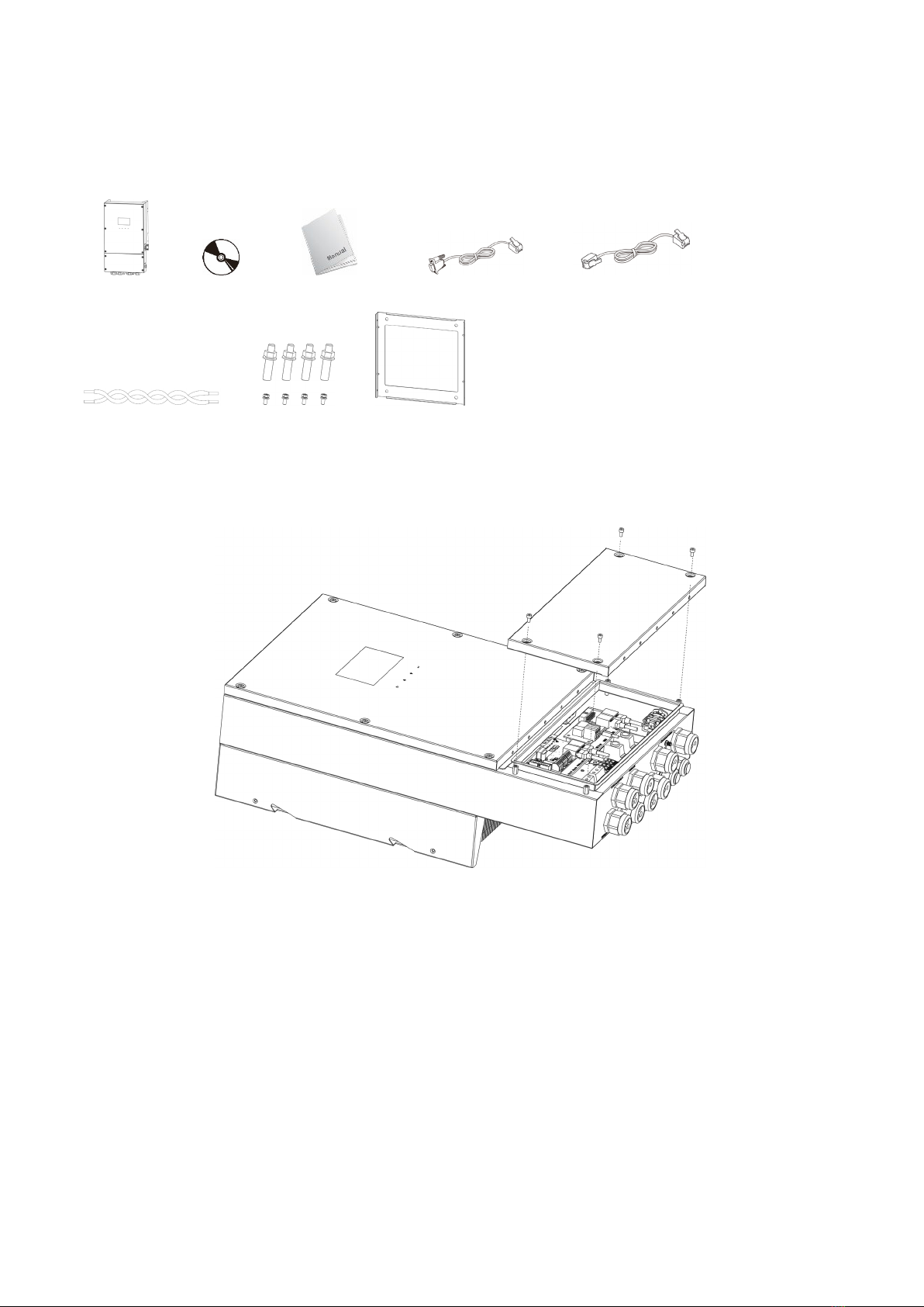
Before installation, please inspect the unit. Be sure that nothing inside the package is damaged. You should
have received the following items inside of package:
Inverter unit Software CD Manual RS-232 cable Parallel communication cable
Current sharing cable Fixing screws Mounting plate
Preparation
Before connecting all wirings, please take off bottom cover by removing four screws as shown below.
Installing the Unit
Preparation
This hybrid inverter is designed for indoor or outdoor use (IP65), please make sure the installation site meets
below conditions:
Not in direct sunlight
Not in areas where highly flammable materials are stored.
Not in potential explosive areas.
Not in the cool air directly.
Not near the television Antenna or antenna cable.
Not higher than altitude of about 2000 meters above sea level.
Not in environment of precipitation or humidity (>95%).
Please AVOID direct sunlight, rain exposure, snow laying up during installation and operation.
Select the Mounting Place
Please select a vertical wall with load-bearing capacity for installation, appropriate for installation on
concrete or other non-flammable surfaces.
The ambient temperature should be between -25~60℃to ensure optimal operation.

5
Be sure to keep other objects and surfaces as shown in the diagram to guarantee sufficient heat dissipation
and have enough space for removing wires.
For proper air ventilation to dissipate heat, allow a clearance of approx. 50cm to the side and approx.
50cm above and below the unit. And 100cm toward the fro
Mounting the Unit
WARNING!! Remember that this inverter is heavy! Please be careful when lifting out from the package.
Installation to the wall should be implemented with the proper screws. After that, the device should be bolted
on securely.
The inverter only can be used in a CLOSED ELECTRICAL OPERATING AREA. Only serviceperson can enter this
area.
1.
Put the mounting plate against the wall. Fix the
mounting plate with the supplied four scr
ews as
shown in the chart. The reference tightening torque is
35 N.m.
2. Raise the inverter and place it over the mounting
plate.
3. Fix the inverter in position by screwing the supplied
four screws (M5*4) located on the two sides of the
inverter.
4. Check if the inverter is firmly secured.
WARNING!! FIRE HAZARD.
SUITABLE FOR MOUNTING ON CONCRETE OR OTHER NON-COMBUSTIBLE SURFACE ONLY.
6
Battery Connection
CAUTION: For safety operation and regulation compliance, it’s requested to install a separate DC over-current
protector or disconnect device between battery and inverter. It may not be requested to have a disconnect
device in some applications, however, it’s still requested to have over-current protection installed. Please refer
to typical amperage in below table as required fuse or breaker size.
WARNING! All wiring must be performed by a qualified personnel.
WARNING! It's very important for system safety and efficient operation to use
appropriate cable for battery connection. To reduce risk of injury, please use the
proper recommended cable and terminal size as below.
Recommended battery cable and terminal size:
Model Typical
Amperage
Battery
Capacity Wire Size Torque
Value
ELEGO-6KW-IP65 104/125A 200AH
1*2AWG 2~3 Nm
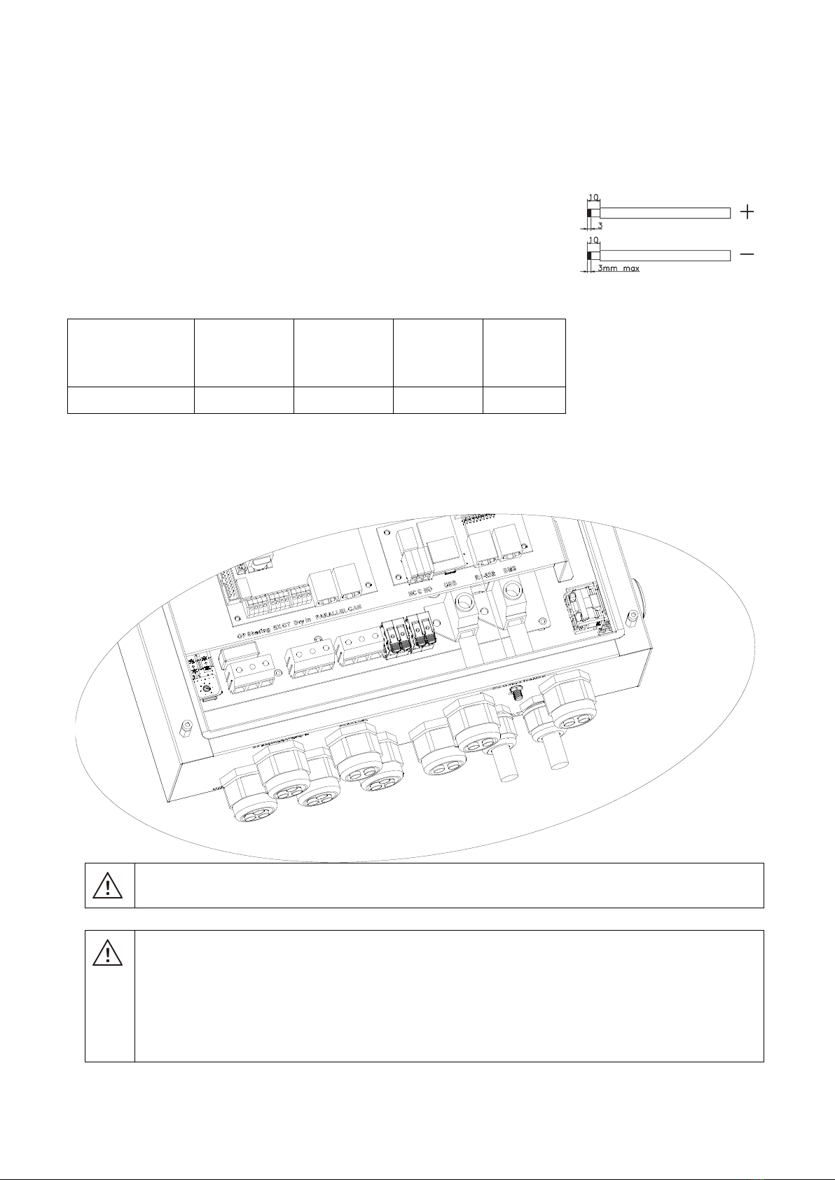
Please follow the below steps to implement battery connection:
1. Remove insulation sleeve 7mm for two conductors.
2. Insert battery wires according to polarities indicated on the terminal block and tighten the terminal screws.
Make sure polarity at both the battery and the inverter/charge is correctly connected.
WARNING: Shock Hazard
Installation must be performed with care due to high battery voltage in series.
CAUTION!! Do not place anything between the flat part of the inverter terminal and the ring
terminal. Otherwise, overheating may occur.
CAUTION!! Do not apply anti-oxidant substance on the terminals before terminals are connected
tightly.
CAUTION!! Before making the final DC connection or closing DC breaker/disconnector, be sure
positive (+) must be connected to positive (+) and negative (-) must be connected to negative (-).
7
AC Input/Output Connection
CAUTION!! Before connecting to AC input power source, please install a separate AC breaker between
inverter and AC input power source. This will ensure the inverter can be securely disconnected during
maintenance and fully protected from over current of AC input.
CAUTION!! There are two terminal blocks with “IN” and “OUT” markings. Please do NOT mis-connect input
and output connectors.
WARNING! All wiring must be performed by a qualified personnel.
WARNING! It's very important for system safety and efficient operation to use
appropriate cable for AC input connection. To reduce risk of injury, please use the
proper recommended cable size as below.
Suggested cable requirement for AC wires
Model Gauge Torque Value
ELEGO-6KW-IP65 10 AWG 1.2~ 1.6 Nm
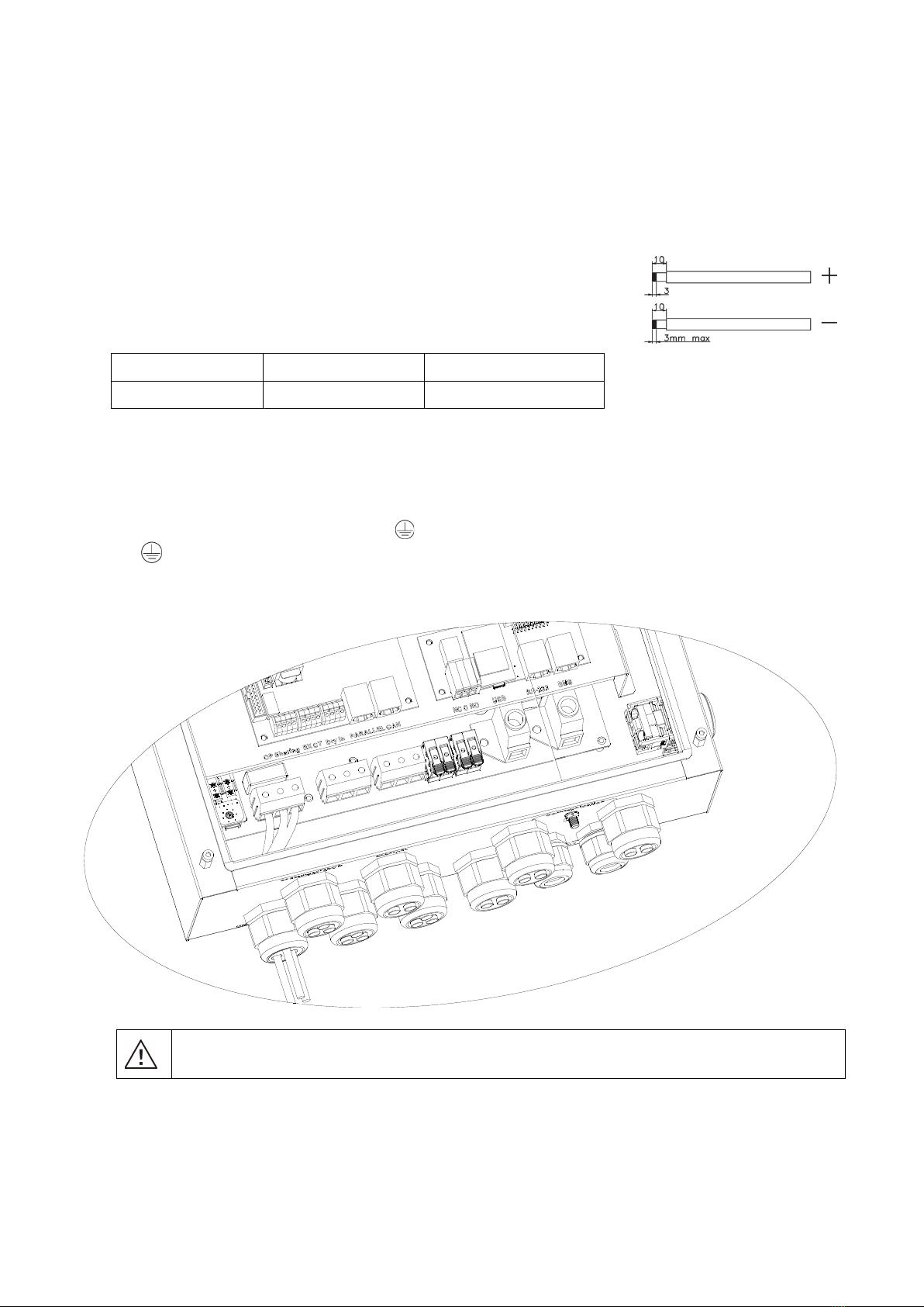
Please follow below steps to implement AC input/output connection:
1. Before making AC input/output connection, be sure to open DC protector or disconnector first.
2. Remove insulation sleeve 7mm for six conductors.
3. Insert AC input wires according to polarities indicated on terminal block and tighten the terminal screws. Be
sure to connect PE protective conductor ( ) first.
→Ground (yellow-green)
L→LINE (brown or black)
N→Neutral (blue)
WARNING:
Be sure that AC power source is disconnected before attempting to hardwire it to the unit.
8
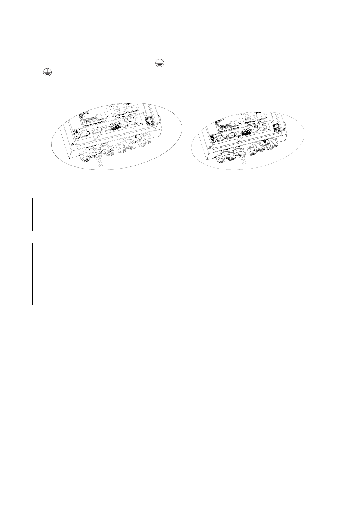
4. This inverter is equipped with dual-output. There are two outputs: AC output 1 and AC output 2. It’s set up
through LCD program or monitoring software to turn on and off the second output. Refer to “LCD setting”
section for the details.
Insert AC output wires according to polarities indicated on terminal block and tighten terminal screws. Be
sure to connect PE protective conductor ( ) first.
→Ground (yellow-green)
L→LINE (brown or black)
N→Neutral (blue)
AC Output 1 AC Output 2
5. Make sure the wires are securely connected.
CAUTION:Appliances such as air conditioner are required at least 2~3 minutes to restart because it’s required
to have enough time to balance refrigerant gas inside of circuits. If a power shortage occurs and recovers in a
short time, it will cause damage to your connected appliances. To prevent this kind of damage, please check
manufacturer of air conditioner if it’s equipped with time-delay function before installation. Otherwise, this
inverter/charger will trig overload fault and cut off output to protect your appliance but sometimes it still causes
internal damage to the air conditioner.
CAUTION: Important
Be sure to connect AC wires with correct polarity. If L and N wires are connected reversely, it may cause
utility short-circuited when these inverters are worked in parallel operation.

9
PV Connection
CAUTION: Before connecting to PV modules, please install separately a DC circuit breaker between inverter
and PV modules.
WARNING! All wiring must be performed by a qualified personnel.
WARNING: Please switch off the inverter before you connect PV modules. Otherwise, it will damage the
inverter.
WARNING! It's very important for system safety and efficient operation to use appropriate cable for PV
module connection. To reduce risk of injury, please use the proper recommended cable size as below.
Model Typical Amperage Cable Size Torque
ELEGO-6KW-IP65 27A/30A 8AWG 2.0~2.4Nm
PV Module Selection:
When selecting proper PV modules, please be sure to consider below parameters:
1. Open circuit Voltage (Voc) of PV modules not exceeds max. PV array open circuit voltage of inverter.
2. Open circuit Voltage (Voc) of PV modules should be higher than min. battery voltage.
Solar Charging Mode
INVERTER MODEL ELEGO-6KW-IP65
Max. PV Array Open Circuit Voltage 550 Vdc
PV Array MPPT Voltage Range 120~450Vdc
MPP Number 1
Please follow below steps to implement PV module connection:
1. Remove insulation sleeve 7 mm for positive and negative conductors.
2. Check correct polarity of connection cable from PV modules and PV input
connectors. Then, connect positive pole (+) of connection cable to positive pole
(+) of PV input connector. Connect negative pole (-) of connection cable to
negative pole (-) of PV input connector.
Recommended PV module Configuration
PV Module Spec.
(reference)
- 250Wp
- Vmp: 30.7Vdc
- Imp: 8.15A
- Voc: 37.4Vdc
- Isc: 8.63A
- Cells: 60
Total solar input power Solar input Q'ty of modules
1500W 6 pieces in series 6 pcs
2000W 8 pieces in series 8 pcs
2750W 11 pieces in series 11 pcs
3000W 6 pieces in series
2 strings in parallel 12 pcs
4000W 8 pieces in series
2 strings in parallel 16 pcs
5000W 10 pieces in series
2 strings in parallel 20 pcs
6000W 12 pieces in series
2 strings in parallel 24 pcs
10
Communication Connection
Please use the supplied communication cable to connect to the inverter and PC. Follow the below procedure to
connect communication wiring. Insert bundled CD into a computer and follow the on-screen instructions to
install the monitoring software. For the detailed software operation, please check the user manual of the
software inside of a CD.
For RS232 port, you should use a RJ45 cable as follows:
For USB port, you should use a USB cable as follows:
PIN1: TXD, PIN2:RXD, PIN4:12V, PIN8:GND
The RJ45 line sequence is as follows:
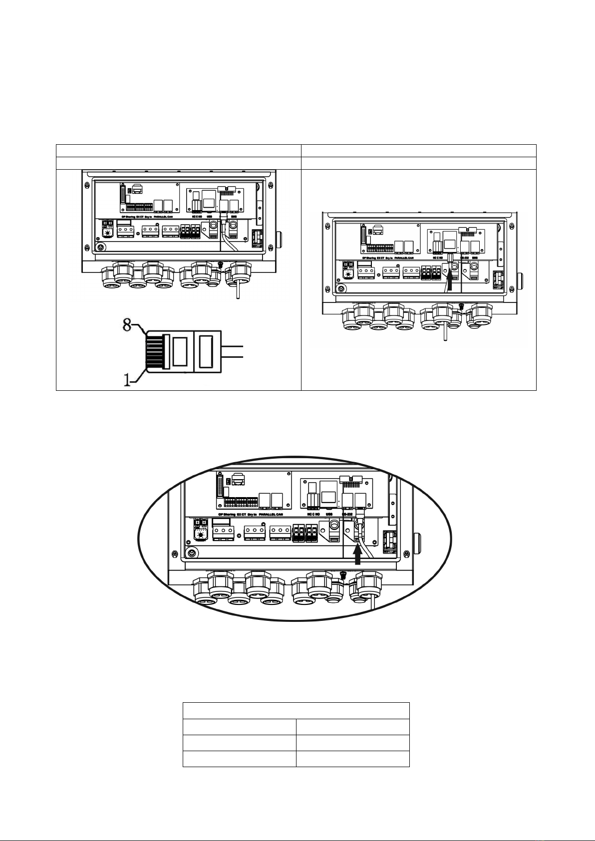
BMS Communication
For BMS port, you should use a RJ45 cable as follows:
It is recommended to purchase a special communication cable if you are connecting to Lithium-ion battery
banks. Please use a RJ45 cable to connect BMS communication port as shown in below:
PIN Assignment
PIN 3 RS485-B
PIN 5 RS485-A
PIN 8 GND
For more information, please refer to Appendix II: BMS Communication Installation.
11
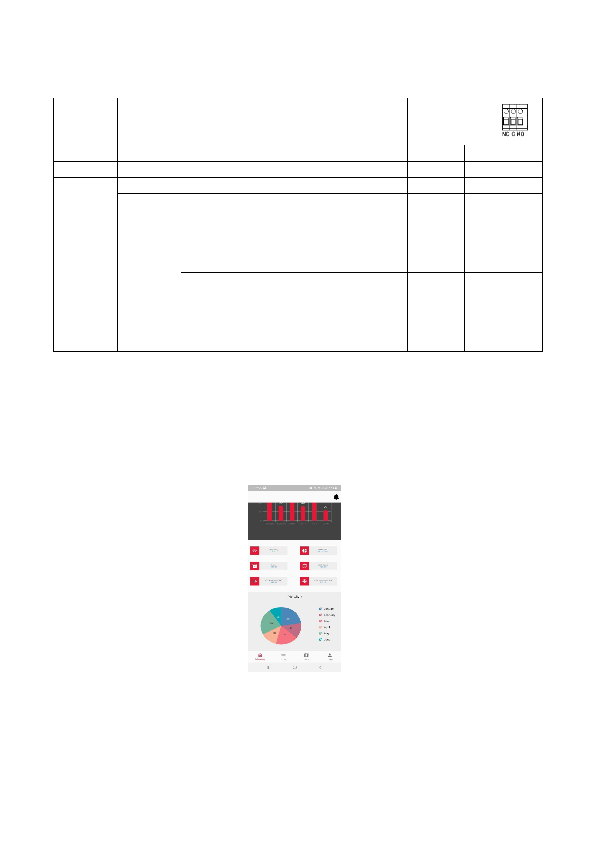
Dry Contact Signal
There is one dry contact (3A/250VAC) available on the rear panel. It could be used to deliver signal to external
device when battery voltage reaches warning level.
Unit Status Condition Dry contact port:
NC & C NO & C
Power Off Unit is off and no output is powered. Close Open
Power On
Output is powered from Utility. Close Open
Output is
powered
from
Battery or
Solar.
Program 01
set as SUB
Battery voltage < Low DC warning
voltage Open Close
Battery voltage > Setting value in
Program 21 or battery charging
reaches floating stage
Close Open
Program 01
is
set as
SBU
Battery voltage < Setting value in
Program 20 Open Close
Battery voltage > Setting value in
Program 21 or battery charging
reaches floating stage
Close Open
Wi-Fi Connection
This unit is equipped with a Wi-Fi transmitter. Wi-Fi transmitter can enable wireless communication between
off-grid inverters and monitoring platform. Users can access and control the monitored inverter with
downloaded APP. You may find “Crown Monitor” app from the Apple® Store or Google® Play Store. All data
loggers and parameters are saved in iCloud. For quick installation and operation, please refer to Appendix III -
The Wi-Fi Operation Guide for details.
12
OPERATION
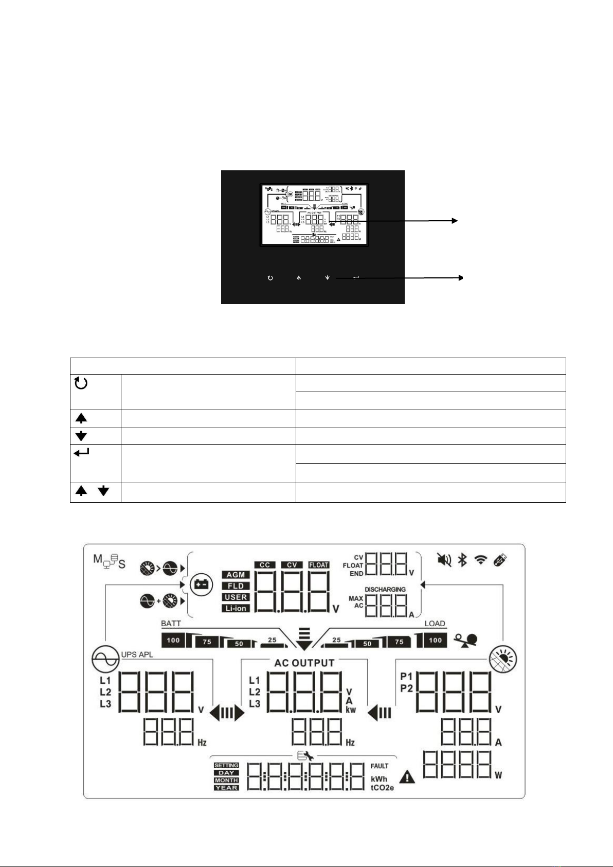
Operation and Display Panel
The operation LCD panel, shown in the chart below, includes four touchable function keys and a LCD display to
indicate the operating status and input/output power information.
Touchable Function Keys
Function Key Description
ESC To exit the setting
Power off(1S)
Up To last selection
Down To next selection
Enter To c o n f i r m/enter the selection in setting mode
Power on(1S)
+ Up+Down To c o n f i rm (1.5S)
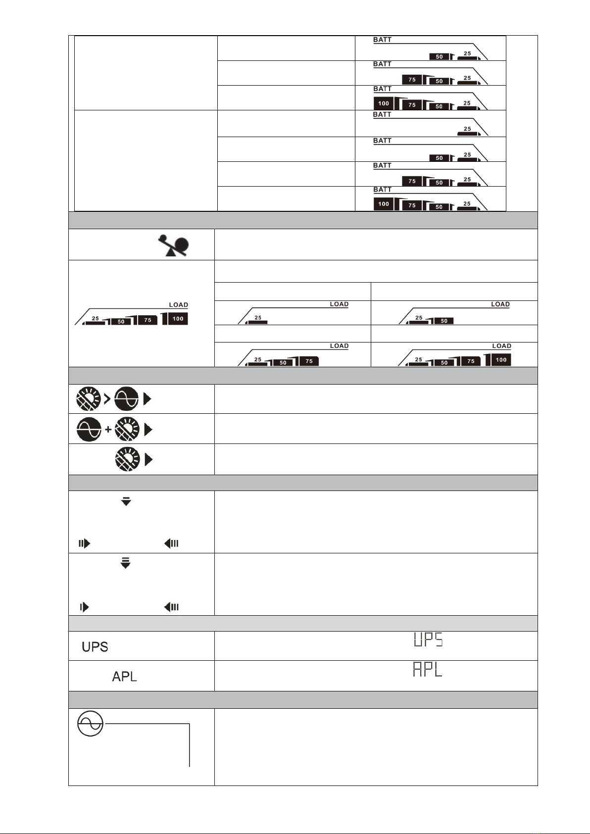
LCD Display Icons
LCD Display
Touchable
function keys

13
Icon Function description
Input Source Information
Indicates the AC input voltage and frequency.
Indicates the PV voltage, current and power.
Indicates the battery voltage, charging stage, configured battery
parameters, charging or discharging current.
Configuration Program and Fault Information
Indicates the setting programs.
Indicates the warning and fault codes.
Warning: flashing with warning code.
Fault: lighting with fault code.
Output Information
Indicate the output voltage, load in VA, load in Watt and output
frequency.
Battery Information
Indicates battery level in battery mode and charging status in line mode
by 0-24%, 25-49%, 50-74% and 75-100%.
When battery is charging, it will present battery charging status.
Status Battery voltage LCD Display
Constant
Current mode /
Constant
Voltage mode
<2V/cell
4 bars will flash in turns.
2 ~ 2.083V/cell
The right bar will be on and the other three bars
will flash in turns.
2.083 ~ 2.167V/cell
The right two bars will be on and the other two
bars will flash in turns.
> 2.167 V/cell The right three bars will be on and the left bar
will flash.
Floating mode. Batteries are fully charged. 4 bars will be on.
In battery mode, it will present battery capacity.
Load Percentage Battery Voltage LCD Display
Load >50% < 1.85V/cell
14
1.85V/cell ~ 1.933V/cell
1.933V/cell ~ 2.017V/cell
> 2.017V/cell
Load < 50%
< 1.892V/cell
1.892V/cell ~ 1.975V/cell
1.975V/cell ~ 2.058V/cell
> 2.058V/cell
Load Information
Indicates overload.
Indicates the load level by 0-24%, 25-49%, 50-74% and 75-100%.
0%~24% 25%~49%
50%~74%
75%~100%
Charger Source Priority Setting Display
Indicates setting program 10 “Charger source priority” is selected as
“Solar first”.
Indicates setting program 10 “Charger source priority” is selected as
“Solar and Utility”.
Indicates setting program 10 “Charger source priority” is selected as
“Solar only”.
Output source priority setting display
Indicates setting program 01 “Output source priority” is selected as
“S UB”.
Indicates setting program 01 “Output source priority” is selected as
“SB U”.
AC Input Voltage Range Setting Display
Indicates setting program 02 is selected as “ ”. The acceptable AC
input voltage range will be within 170-280VAC.
Indicates setting program 02 is selected as “ ”. The acceptable AC
input voltage range will be within 90-280VAC.
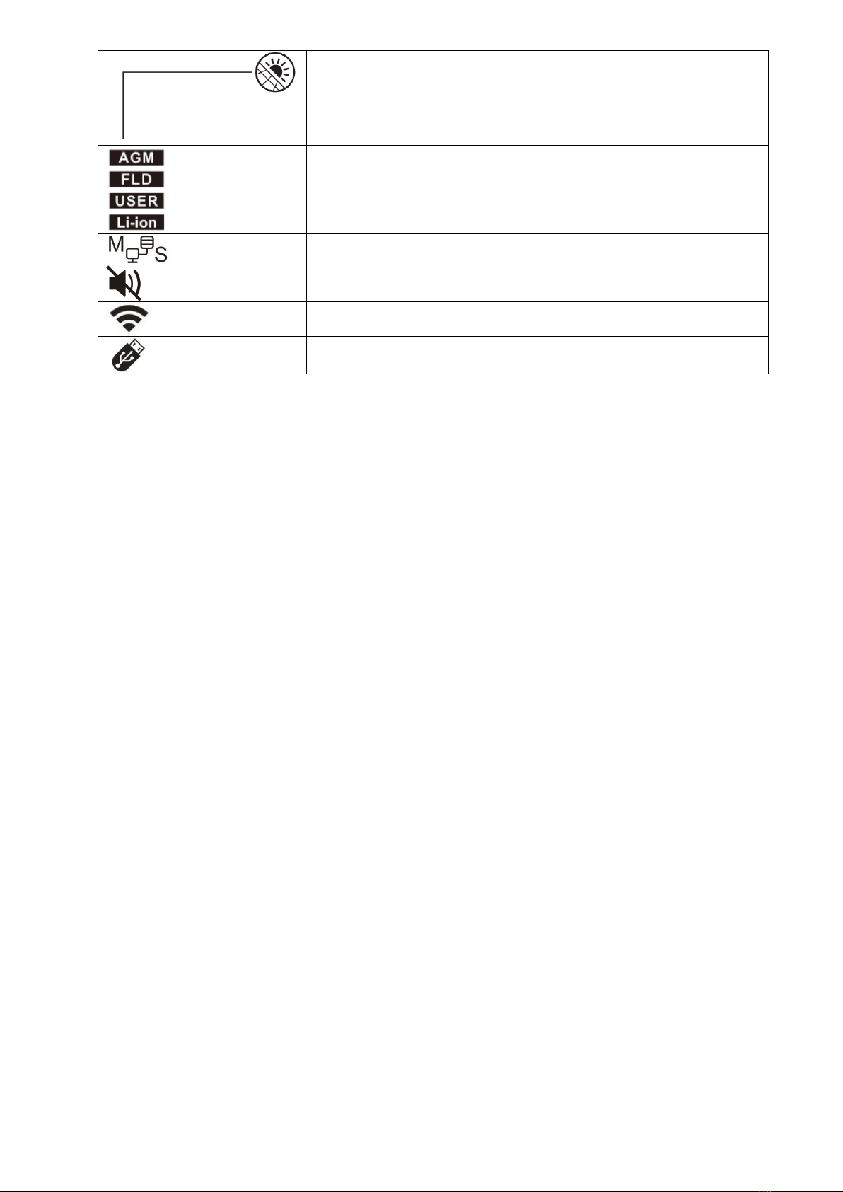
Operation Status Information
Indicates unit connects to the mains.
15
Indicates unit connects to the PV panel.
Indicates battery type.
Indicates parallel operation is working.
Indicates unit alarm is disabled.
Indicates Wi-Fi transmission is working.
Indicates USB disk is connected.

16
LCD Setting
After pressing and holding “UP”and ”DOWN”buttons for 1.5 seconds, the unit will enter setting mode. Press
“UP” or “DOWN” button to select setting programs. And then, press “ENTER” button to confirm the selection or
ESC button to exit.
Program Description Selectable option
00 Exit setting mode
Escape
01
Output source priority
selection
SUB(default)
Solar energy provides power to the
loads as first priority.
If solar energy is not sufficient to
power all connected loads, Utility
energy will supply power to the loads
at the same time.
SBU
Solar energy provides power to the
loads as first priority.
If solar energy is not sufficient to
power all connected loads, battery
energy will supply power to the loads
at the same time.
Utility provides power to the loads
only when battery voltage drops to
either low-level warning voltage or the
setting point in program 20 or solar
and battery is not sufficient.
02 AC input voltage range
Appliances (default)
If selected, acceptable AC input
voltage range will be within
90-280VAC.
UPS
If selected, acceptable AC input
voltage range will be within
170-280VAC.
03 Output voltage
220Vac
230V (Default)

17
240Vac
04 Output frequency
50Hz (default)
60Hz
05 Solar supply priority
Charge battery first
(default)
Solar energy provides power to charge
battery as first priority.
Power the loads first
Solar energy provides power to the
loads as first priority.
06
Overload bypass:
When enabled, the unit
will transfer to line
mode if overload occurs
in battery mode.
Bypass disable
Bypass enable (default)
07 Auto restart when
overload occurs
Restart disable (default)
Restart enable
08 Auto restart when over
temperature occurs
Restart disable (default)
Restart enable
09
Solar energy feed to
grid configuration
Feed to grid disable
(default)
If selected, solar energy is not allowed
to feed to the grid.
Feed to grid enable
If selected, solar energy is allowed to
feed to the grid.
18
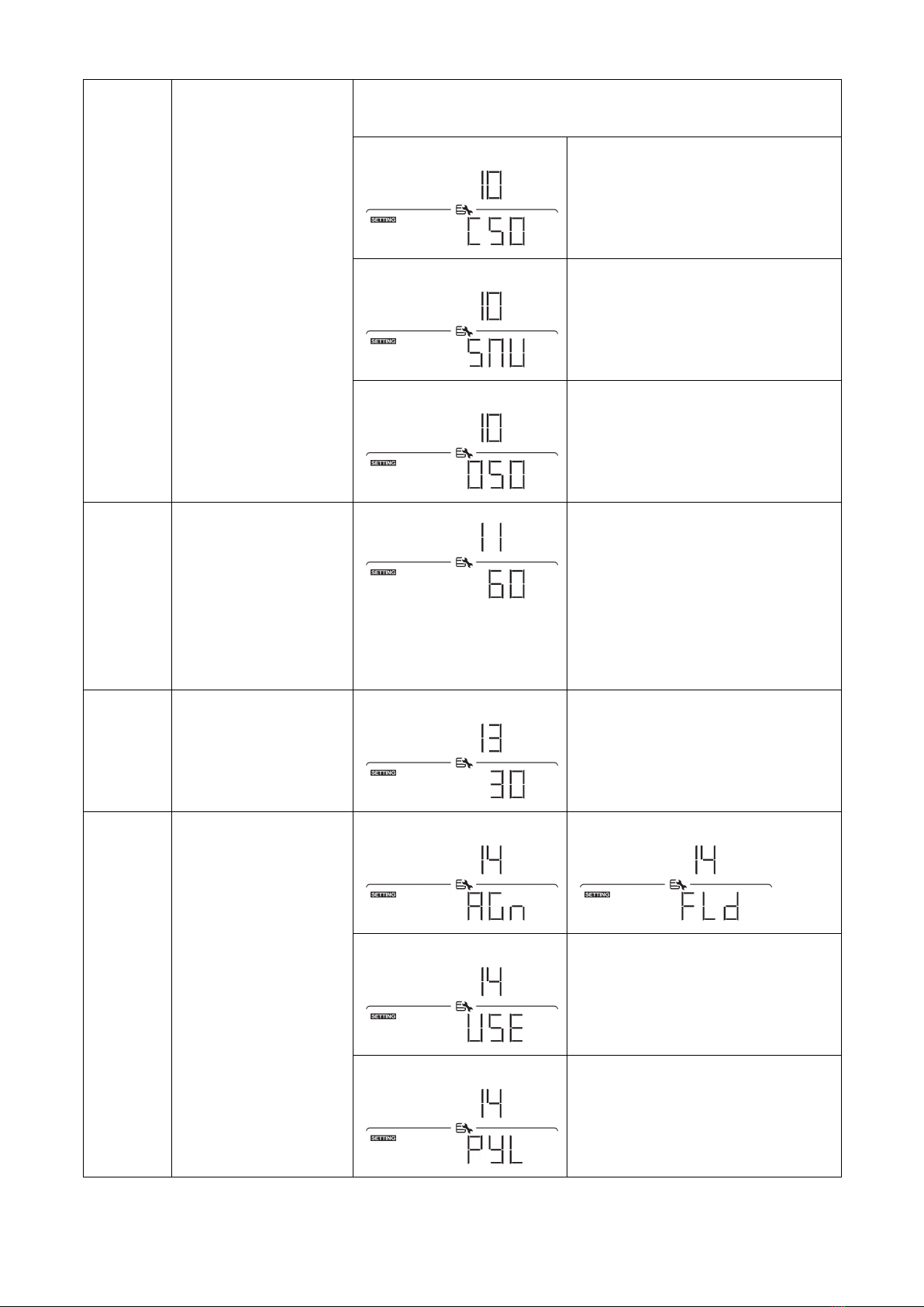
10
Charger source priority:
To configure charger
source priority
If this inverter/charger is working in Line, Standby or Fault mode,
charger source can be programmed as below:
Solar first
Solar energy will charge battery as
first priority.
Utility will charge battery only when
solar energy is not available.
Solar and Utility (default)
Solar energy and utility will charge
battery at the same time.
Only Solar
Solar energy will be the only charger
source no matter utility is available or
not.
11
Maximum charging
current:
To configure total
charging current for
solar and utility
chargers.
(Max. charging current
= utility charging
current + solar charging
current)
60A (default)
For ELEGO-6KW-IP65 model, setting
range is from 10A to 120A.
Increment of each click is 10A.
13 Maximum utility
charging current
30A (default)
For ELEGO-6KW-IP65 model, setting
range is from 2A to 120A.
Increment of each click is 10A.
14 Battery type
AGM (default)
Flooded
User-Defined
If “User-Defined” is selected, battery
charge voltage and low DC cut-off
voltage can be set up in program 17,
18 and 19.
Pylontech battery
If selected, programs of 11, 17, 18
and 19 will be automatically set up.
No need for further setting.
Table of contents
Other Crown Micro Inverter manuals


Popular Inverter manuals by other brands


Scientific Aviation
Scientific Aviation SOOFIE installation guide

Mitsubishi Electric
Mitsubishi Electric FR-V5NE-E instruction manual

Solahart
Solahart SunCell SOLAHART450H2 installation manual

Megger
Megger AVTM6514J instruction manual

DWT
DWT WaCS PWM 230 manual

Phonocar
Phonocar 5/205 Assembling instructions

Sunny Boy
Sunny Boy 700 Technical description

Reliable Electric
Reliable Electric RB-1000S owner's guide

Mitsubishi Electric
Mitsubishi Electric PV-PNS04ATL-IT Operation manual

Champion Power Equipment
Champion Power Equipment 100319 owner's manual

leco
leco 20006 999 manual

Axpert
Axpert Max 7200 Service manual