TABLE
OF
CONTENTS
SECTION
I
GENERAL
OPERATIQN
PAGE
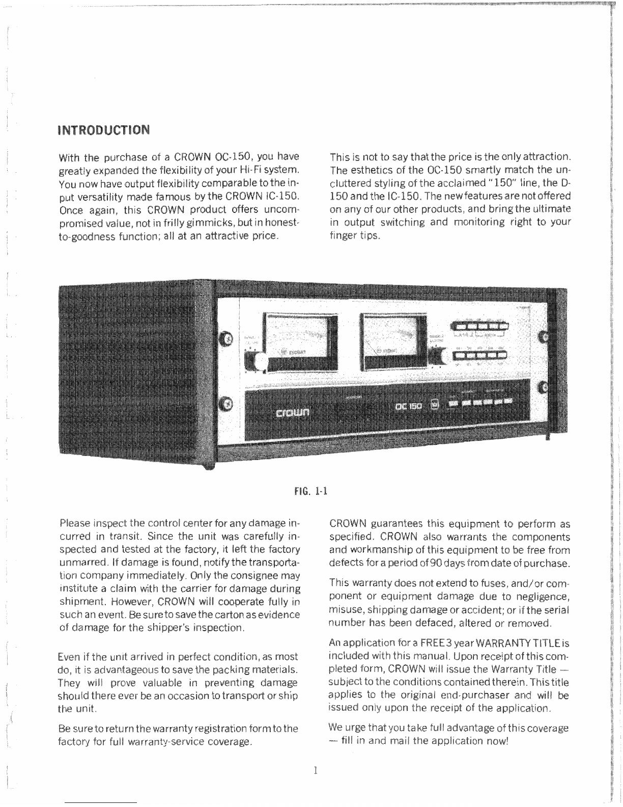
lntroductian
.................................................................................................................
1
Warranty
&
Unpacking
...............................................................................................
1
..........................................................................................................
Quick
Summary
2
Front
Pane[
Contrsi
Functions
...................................................................................
2
Rear
Panel
Connectars
...................
,.....
....................*.........................................
3
Complete
Ca;lnnectisn
of
inputs
................................................................................
4
..............................................................................
Campiete
Connection
of
Outputs
5
....................................................................................
Camman
Usage
Procedures
6
Mounting
Instructions
................................................................................................
8
..............................................................................................................
Specifications
9
SECTlON
I!
TECHNlGAL
DESCRIPTION
AND
USE
Introduction
...............................................................................................................
15
.................................................................................................
inputdOutput
Sg~cs
42
........................................................................
Meter
Response
and
interpretalion
14
....................................................................................................
Circuit
&scription
48
.............................................................................
Headphone
Attenuator
Switches
18
Crsrsstal
k
&
Sparation
.......
..
....................................................................................
18
Care
of
the
06-150
...................................................................................................
18
.................................................................................................
220
Volt
Conversion
18
.......................................................................................................
Warranty
srvice
19