Crown Aut-o-doR 1502-1 User manual

G-1001-R1
Crown Industrial Operators
(Formerly manufactured by Richards-Wilcox)
213 Michelle Court
So. San Francisco, CA 94080
Phone (650) 952-5150
Fax (650) 873-1495
website: www.crown-industrial.com
Copyright © Crown Industrial Operators 2011
GENERAL
INSTALLATION,
OPERATION,
MAINTENANCE,
and PARTS MANUAL
for your
1502-1 & 1502-2
SWING DOOR- Heavy Duty
OPERATORS
CROW N
NDUSTRAI IL
OPERATORS

CONTENTS
PARAGRAPH PAGE
1 INTRODUCTION ............................................................................... 1
A Purpose......................................................................................... 1
B Models Covered ............................................................................ 1
C Application..................................................................................... 1
D Description .................................................................................... 1
2 INSTALLATION AND OPERATION ................................................... 1
A General ......................................................................................... 1
Push and Pull Arm Assembly ........................................................ 2
B Mounting the Operator .................................................................. 3
C Wiring Operator and Controls ....................................................... 3
D Start Up ......................................................................................... 3
E Check Operation Motor ................................................................. 4
F Setting Electric Clutch Resistence ............................................... 5
G Setting Run Timer ......................................................................... 5
3 MAINTENANCE ................................................................................ 5
A General ......................................................................................... 5
4 PARTS............................................................................................... 6
A To Order Replacement Parts......................................................... 6
B Parts List ....................................................................................... 6&7
WARRANTY ...................................................................................... 11
Note: We reserve the right to modify or change, without prior notice,
any statements or information contained herein. If exact dimensions
or specications are required by the customer certied prints will
be furnished without charge upon request to Crown Industrial. This
manual covers standard catalogued operators only and does not cover
special non-standard equipment.
Crown Industrial Operators • 213 Michelle Ct. • So. San Francisco, Ca 94080-6202
Phone: (650) 952-5150 • Fax: (650) 873-1495

1. INTRODUCTION
A. PURPOSE: This Crown Installation, Operation,
Maintenance and Parts Manual has been developed to
assist you in the installation, operation and maintenance
of your electric operator and thus enable you to utilize it
to its maximum eciency.
B. MODELS COVERED: The manual covers current
models 1502-1 & 1502-2 Operators.
C. APPLICATION: The Crown Industrial Model #1502
Swing Door Operators are intended for use on large
interior industrial doors operated by trained personnel.
D. DESCRIPTION:
The model 1502 operator consists of a 90 volt, DC
permanent magnet gear motor, variable torque electric
clutch, right angle worm gear and internal limit switches.
The motor control is accomplished by means of an
electronic control package. The motor controls are
mounted in a remotely located control panel. The
operator shall mount above the door on the lintel of the
frame. Door connecting arms and door brackets are
included. The operator mounting frame and cover shall
be prime coated ready for nish painting in the eld. The
supply voltage should be 120 volt AC, single phase. The
control circuit will allow for two speed operation with the
run and creep speeds independently adjustable.
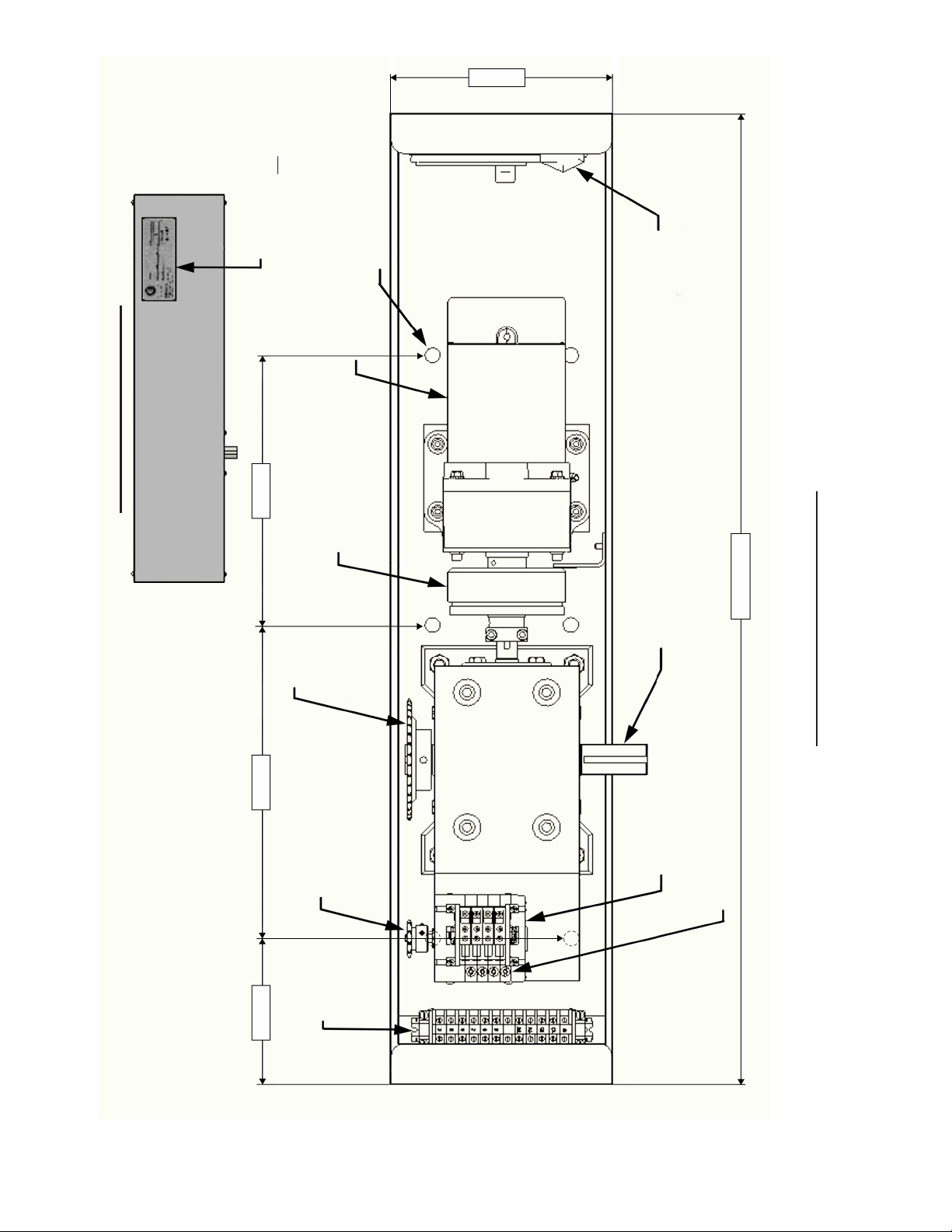
Figure 1. 1502 Left Hand Swing Door
Operator
2. INSTALLATION AND OPERATION
A. GENERAL
The Crown 1502 Electric Door Operator has been
designed primarily for commercial and industrial
installations where the operator has to withstand
constant hard use. To ensure correct installation
and proper operation of the operator and associated
hardware, the following instructions are given:
(1) SHIPMENT CHECK: Included with the installation
packet is a copy of the packing slip for the components
supplied with the order. Compare the components
received with the packing slip to insure that all
equipment is complete.
(2) REVIEW INSTALLATION DRAWINGS: The
installation drawings show the layout of the door,
template drilling for the door and jamb, and general
terms used to describe the components. Review the
drawings to familiarize yourself with the equipment.
(3) CHECK THE DOORS: Prior to installing the
operator, conrm the doors are properly hung. 95% of
all door operator trouble is caused by doors not swinging
free of the oor and lintel. It is also very important that
all hinge pins are properly aligned and there is no hinge
binding.
(4) PREPARING THE DOOR AND LINTEL:
The door operators are handed (left and right) and
are supplied as push or pull to open (Refer to Figure 2
Operator Handing). Ensure proper backing and support
are available in the lintel and the door to receive the
operator and connecting arm. Remove the electric
operator from crate. Choose the appropriate drilling
template. Prepare the lintel for the operator.
Figure 2. Operator Handing
RIGHT HAND PULL TO OPEN
#1502 OPERATOR #1502 OPERATOR
LEFT HAND PULL TO OPEN
HINGE
#1502 OPERATOR #1502 OPERATOR
RIGHT HAND PUSH TO OPEN LEFT HAND PUSH TO OPEN
HINGE
Crown Industrial Operators • 213 Michelle Ct. • So. San Francisco, Ca 94080-6202
Phone: (650) 952-5150 • Fax: (650) 873-1495
Crown Industrial Operators • 213 Michelle Ct. • So. San Francisco, Ca 94080-6202
Phone: (650) 952-5150 • Fax: (650) 873-1495
Crown Industrial Operators • 213 Michelle Ct. • So. San Francisco, Ca 94080-6202
Phone: (650) 952-5150 • Fax: (650) 873-1495

Operator 1502 is engineered to support
push, pull to open doors both left and right
directions.
Figure 3. 1502-PULLO Operator Assembly
The arm has a roller attached to the end, guided by a track that is mounted on the pull side of the door.
The arm is directly mounted to the operator drive shaft.
Note: For pull to open applications the operator is mounted OPPOSITE of the door hinges.
Figure 4. 1502-PUSHO Operator Assembly
The angle bracket is mounted to the face of the door with fasteners, while the other end mounts
directly to the operator drive shaft.
Note: For push to open applications the operator is mounted OPPOSITE of the door hinges.
PUSH AND PULL
ARM ASSEMBLY
#1502-PULLO
#1502-PUSHO
Operator 1502 (Mounted to
Lintel with 6 Ea 1/2’"
Fasteners
Door
Frame
Door
Operator 1502 (Mounted to
Lintel with 6 Ea 1/2’"
Fasteners
Door
Frame
Door
Crown Industrial Operators • 213 Michelle Ct. • So. San Francisco, Ca 94080-6202
Phone: (650) 952-5150 • Fax: (650) 873-1495

B. MOUNTING THE OPERATOR
Mount the operator according to the chosen illustration
on page 2. The operator must be installed level. With
the door in the closed position drill the door to receive
the door bracket (Note: fasteners are supplied by
others). Attach the arms from the operator to the door
bracket. Manually swing door open and closed ensuring
both the door and operator function freely.
C. WIRING OPERATOR AND CONTROLS:
(1) No. 1502 Electric Operators are intended for
applications with motor branch circuits that have voltage
and current characteristics to meet the operators’
ratings. Branch circuit, branch circuit disconnecting
means, and branch circuit over current protection are to
be properly sized in respect to the operators’ horsepower
rating.
WARNING: Insure operator branch circuit is
disconnected from power source when installing,
adjusting or servicing operator.
(2) Be sure all power is o. Wire the electric operator
and controls according to the wiring diagrams provided
in the installation packet.
D. START-UP:
(1) Conrm all wires are correctly connected to
terminals. Reference wiring schematic provided in the
installation packet.
(2) LIMIT SWITCH ADJUSTMENT:
(a) Disconnect the Electrical Power Supply to the
Operator Control Box.
(b) Unscrew limit switch cover and expose assembly.
Reference Figure 3. Rotary Cam Limit Switch
Assembly.
Note: For right hand pull to open or left hand push to
open operators.
(a) LSO = Limit Switch Open (Wired Normally Closed)
This limit shuts o the electric operator when the
door reaches the full open position. (Light on
PLC turns OFF when activated)
(b) LSC = Limit Switch Close (Wired Normally Closed)
This limit shuts o the operator when the door
has reaches the full closed position. (Light on
PLC turns OFF when activated)
(c) LSCO = Limit Switch Creep Open (Wired Normally
Open)
This limit activates the creep mode during the
end of open cycle. When the limit switch is
actuated the door travels in the open direction at
a reduced speed. (Light on PLC turns ON when
activated)
(d) LSCC = Limit Switch Creep Close (Wired Normally
Open)
This limit activates the creep mode during the
closing cycle. When this limit switch is actuated
the door travels in the closed direction at a
reduced speed. (Light on PLC turns ON when
activated)
U.L. recognized snap-action
switches. Supplied as
SPDT, DPDT optional.
Rotary Cam Limit
Switch Assembly
SRLS51-( )-SP4
Plastic planetary gear
reduction stages. Sun gear
is input, ring gear is
stationary, planet carrier is
output. No lubrication.
17.5
29
75
Independent cam
adjusting screw with
self-locking adjustment.
Gear switching stages are
same as gear reduction
stages except cam is on
planet carrier. Sun gears
connected in parallel.
Primary gear stages yield
mulitiplier for
input/cam shaft ratio.
Figure 5. Rotary Cam Limit Switch Assembly
Crown Industrial Operators • 213 Michelle Ct. • So. San Francisco, Ca 94080-6202
Phone: (650) 952-5150 • Fax: (650) 873-1495

Figure 6. Safe Swinging Power Door Operating Speeds
To adjust each individual limit switch, turn the screw
adjustment for each specic limit switch. Note that
depending upon the handing of the operator the cams
travel from either the clockwise or counterclockwise
direction to activate the appropriate snap switches.
(e) With the power turned o, manually swing the
door to the full close position. Check to see LSC (limit
switch close) is engaged. You can see the pointed cam
engaged the limit switch roller. Adjust the limit switch by
turning the limit switch adjusting screw until the cam just
engages the roller. You should hear the snap switch click
when it is actuated.
(f) With the power turned o, manually swing the
door to the full open position. Check the see LSO
(limit switch open] is engaged. You can see the cam
engaged the limit switch roller. Adjust the limit switch by
turning the limit switch adjusting screw until the cam just
engages the roller.
(g) With the power turned o, manually swing the
door to the full close position. Check to see LSCC
(limit switch creep close) is engaged. You can see the
extended can engage the limit switch roller. Adjust the
limit switch by turning the limit switch adjusting screw
until half of the extended cam travels past the roller.
When this limit switch roller is engaged the door will
travel at the creep speed during the closing cycle (creep
speeds are desirable during the nal opening and
closing positions for smooth operation).
(h) With the power still o, manually swing the
door to the full close position. Check to see LSCO (
limit switch creep open) is engaged. You can see the
extended can engage the limit switch roller. Adjust the
limit switch by turning the limit switch adjusting screw
until half of the extended cam travels past the roller.
When this limit switch roller is engaged adorable travel
at the creep speed during the opening cycle.
(3) Turn the Electric Clutch Controller in a
counterclockwise direction until "o".
(4) Turn the run-speed pot clockwise about half-way and
then turn the creep-speed pot clockwise to about 1/8 of
the way. Reference electrical schematic for the location
of both run and creep pots. Reference Figure 6. Safe
Swinging Power Door Operating Speeds.
Crown Industrial Operators • 213 Michelle Ct. • So. San Francisco, Ca 94080-6202
Phone: (650) 952-5150 • Fax: (650) 873-1495

3. MAINTENANCE
A. GENERAL
Very little maintenance is required on the 1502.
1. Periodically check for wear on the pivot points of the
arms.
2. Operators using the push arm assembly, should
have the two (2) zerk ttings greased once a year
depending on use.
3. Check electric clutch for proper function once a
month depending upon use. Fine tune though
electric clutch torque setting per installation manual
(Refer to step 6, Setting Electric Clutch Resistance).
4. Verify limit switches are set correctly. Periodically
check limit switches for proper adjustment.
(5) CHECK THE OPERATION OF THE MOTOR:
(a) Turn the power on.
(b) Activate the door actuator, verify that the motor is
turning in the correct direction.
The open relay "O" should light during the opening cycle
and the close relay "C" should light during the close
cycle. If they are opposite, the leads (M1 and M2) to
the motor may be switched and the motor rotation will
reverse.
(6) SETTING ELECTRIC CLUTCH RESISTANCE:
(a) Turn the Clutch Controller in a Clockwise
Direction to approximately 50%.
(b) Stand clear of door and pushed open actuator
button. Does the door begin the move without the clutch
slipping?
• If yes, then attempt to stop the door by applying
a pressure to the lead edge of the moving door once
the door has reached approximately the middle of the
opening. The clutch should begin to slip at and applied
pressure of approximately 25 lbs. Adjust the PS90
clutch controller accordingly.
• If no, then increase clutch torque clockwise on
the Clutch Controller until the door begins to move. For
each adjustment be sure to stand clear of the door.
(7) Reset the run and creep speed pots in the control
box to a combined equivalent speed ASP as ed in the
table on Safe Swinging Power Door Operating Speeds
(table on page 4). Be sure speeds are set for smooth
and safe operation of the door.
(8) Fine tune limit switches by repeating step 2 parts A
through D.
(9) SETTING RUN TIMER: (refer to electric schematic)
The run timer is an equipment safety feature which shuts
o the electric motor. Set the run timer to shut o 10
seconds after a complete for close or open cycle.
(a) With the door and the full open position, depress
the actuator switch to signal operator to close the door.
(b) Allow door to fully close while watching the run
timer indicator light (Reference electrical schematic).
The run timer light should stay on approximately 10
seconds after the door has reached the full closed
position. If the run timer light is lit for more than or
less than this 10 second integral, adjust the run timer
pot accordingly. Turning the run timer clockwise will
increase the length of time. Turning the run timer
counterclockwise will decrease the length of time.
(10) OPTIONAL: Partial Open Feature
(a) Close the door to the full close position.
(b) Actuate partial open actuator, the door should
open approximately half-way and shut o. Turn the
partial open timer clockwise to increase the open width.
Turn the partial open timer counterclockwise to decrease
the open width (Refer to electrical schematic).
Crown Industrial Operators • 213 Michelle Ct. • So. San Francisco, Ca 94080-6202
Phone: (650) 952-5150 • Fax: (650) 873-1495

4. PARTS
A. TO ORDER REPLACEMENT PARTS
Order all replacement parts using the number shown on
the following parts list pages.
(1) SEND IN SERIAL NUMBER OF ELECTRIC
OPERATOR.
(2) SPECIFY the number of pieces needed.
(3) Order by part number and name of part.
(4) State whether to ship by freight, truck, parcel
post, or air express
(5) State whether transportation charges are to be
prepaid or collect.
(6) Give name and address of the person or
company to whom the parts are to be shipped.
(7) Give name and address of person or company to
whom the invoices to be sent.
B. PARTS LIST
The following pages list the replacement parts which are illustrated in page 7.
Part Number Description
1502P27 Electric Magnetic Clutch Assembly
1502P35 Adjustable Clutch Controller
1502P63-A 1/4 HP DC Gear Motor
1502-7245 (for model 1502-1) Gearbox 5:1 Ratio
1502-7241 (for model 1502-2) Gearbox 10:1 Ratio
1502P37 Rotary Cam Limit Switch 4:1
1502P38 35B36 Timing Sprocket
1502P40 35B36 Timing Sprocket
1502-PUSHO Push Arm Assembly
1502-PULLO Pull Arm Assembly
Crown Industrial Operators • 213 Michelle Ct. • So. San Francisco, Ca 94080-6202
Phone: (650) 952-5150 • Fax: (650) 873-1495

Terminal
Strip #1502P38
Limit Switch Timing Sprocket
#1502P40
Timing
Sprocket
#1502P40
Electric Magnetic Clutch #1502P63-A
DC Motor
#1502P35
Adjustable Clutch Controller
Gearbox
#1502-7245 (1502-1)
#1502-7241 (1502-2)
#1502PUSHO
#1502PULLO
Note: Push to Open Accessory Pkg
and Pull to Open Accessory Pkg. are not shown.
#1502P37
Limit Switch 4:1
Adjustment Screws for Limit Switch Cams
Operator Name Plate Indicates:
Model #: 1502-
Serial #:
1502 Operator without Cover
1502 Operator w. Cover
8"
6 ea Mounting
Holes for 1/2" Bolts
2-1/4" 14-1/2" 10"
35-1/2" Long
Crown Industrial Operators • 213 Michelle Ct. • So. San Francisco, Ca 94080-6202
Phone: (650) 952-5150 • Fax: (650) 873-1495

Crown Industrial Operators
213 Michelle Court
So. San Francisco, CA 94080
Phone (650) 952-5150
Fax (650) 873-1495
website: www.crown-industrial.com
GUARANTEE
If, within a period of one year from date of shipment, any part of a CIO
Electric "Aut-o-doR" Operator is found defective due to poor materials
or workmanship, new parts will be furnished free of charge F.O.B.
manufacturer’s plant, providing the equipment has been given normal
and proper usage, lubrication, and maintenance and is still the property
of the original purchaser and/or part of the original installation. THIS
WARRANTY IS GIVEN IN LIEU OF ALL OTHER WARRANTIES,
EXPRESSED OR IMPLIED, AND THE MANUFACTURER MAKES
NO IMPLIED WARRANTY OF MERCHANTABILITY BEYOND THE
EXPRESSED TERMS HEREOF. MANUFACTURER’S LIABILITY FOR
DAMAGES, INCLUDING CONSEQUENTIAL DAMAGES RESULTING
FROM ANY SUCH DEFECTIVE PRODUCT IS STRICTLY LIMITED TO
THE DELIVERY OF NEW PARTS, AS SET FORTH ABOVE.
Operator Serial Number _______________________________ H.P. ____________________________________
Supplied on Crown Industrial Operators Order Number __________________________________________________
Power Supply ____________ Volts ___________ Hz _______________ Phase __________________________
Installed At _______________________________ Date _______________________________________________
Notes ________________________________________________________________________________________
________________________________________________________________________________________
________________________________________________________________________________________
________________________________________________________________________________________
________________________________________________________________________________________
MAINTENANCE INFORMATION
(To Be Filled Out By User)
G-996-R1
Crown Industrial Operators • 213 Michelle Ct. • So. San Francisco, Ca 94080-6202
Phone: (650) 952-5150 • Fax: (650) 873-1495
This manual suits for next models
1
Table of contents
Other Crown Door Opening System manuals