Crown 405DC-EC Manual

G-2001
Crown Industrial Operators
(Formerly manufactured by Richards-Wilcox)
213 Michelle Court
So. San Francisco, CA 94080
Phone (650) 952-5150
Fax (650) 873-1495
website: www.crown-industrial.com
Copyright © Crown Industrial Operators 2011
GENERAL
INSTALLATION,
OPERATION,
MAINTENANCE,
and PARTS MANUAL
for your
405DC-EC
SLIDE DOOR
OPERATOR
CROWN
NDUSTRAI IL
OPERATORS

CONTENTS
PARAGRAPH PAGE
1 INTRODUCTION............................................................................... 1
A Purpose......................................................................................... 1
B Models Covered............................................................................ 1
C Application..................................................................................... 1
D Description.................................................................................... 1
2 INSTALLATION AND OPERATION................................................... 1
A General ......................................................................................... 1
B Installation of Track Hardware, Door & Operator .......................... 2
C Installation of Roller Chain............................................................ 2
D Wiring Operator............................................................................. 2
E Motor Rotation............................................................................... 2 & 3
F Preliminary Rotary Limit Switch Adjustment.................................. 3 & 4
G Vent Plug....................................................................................... 4
H Setting The Clutch......................................................................... 4
I Setting Run Speed and Creep Speed........................................... 4
J DC Drive Settings.......................................................................... 5
K Final Rotary Limit Switch Adjustment............................................ 6
L Final Adjustments and Checks...................................................... 6
3 MAINTENANCE ................................................................................ 6
A General ......................................................................................... 6
B Lubrication..................................................................................... 6
C Preventative maintenance............................................................. 6
4 PARTS............................................................................................... 6
A To Order Replacement Parts......................................................... 6
WARRANTY...................................................................................... 7
Note: We reserve the right to modify or change, without prior notice,
any statements or information contained herein. If exact dimensions
or specifications are required by the customer certified prints will
be furnished without charge upon request to Crown Industrial. This
manual covers standard catalogued operators only and does not cover
special non-standard equipment.
Crown Industrial Operators • 213 Michelle Ct. • So. San Francisco, Ca 94080-6202
Phone: (650) 952-5150 • Fax: (650) 873-1495

1. GENERAL INTRODUCTION
A. PURPOSE: This Crown Installation, Operation,
Maintenance and Parts Manual has been developed to
assist you in the installation, operation and maintenance
of your electric operator and thus enable you to utilize it
to its maximum efficiency.
B. MODELS COVERED: The manual covers the
405DC-EC Operator in production and contains the
latest information available. The Model 405DC-EC uses
our Standard Duty Electric Clutch. This operator is used
for powering single sliding or bi-parting doors. The parts
pages have been prepared so you can easily determine
the parts contained in your operator.
C. APPLICATION: The Model 405DC-EC electric
operator offers security as well as the quiet, smooth,
and precise movement of the door(s). The ramp-up
and ramp-down speed functionality helps to control the
overall speed of the door in the final seconds of the
opening and closing cycles. Furthermore, in the event
of power failure, the electric clutch shall disconnect
the doors from the drive train, allowing the doors to
be operated manually. To prevent manual operation a
magnetic lock with a battery backup can be added to the
system.
D. DESCRIPTION:
(1) GENERAL: The Model 405DC-EC operator consists
of a permanent magnet DC motor (1/2 or 1 H.P.), a right
angle gear reducer, an adjustable electric clutch, and a
fully automatic rotary limit switch all assembled into a
complete power drive unit assembly.
(2) TRACK HARDWARE: The 405DC-MC operator is
designed to work with Crown Industrial’s #25 enclosed
Box Track constructed of #9 Ga. steel with 5/8" round
cold steel bar runways. The track is rigidly fixed to the
supporting structure by direct attachment through the
use of steel brackets. The load of the entire door(s) is
carried on rugged heavy duty Crown #25 four wheel ball
bearing trucks. These trucks are driven by roller chain
that operates inside the #25 Box Track. Any chain slack
that accumulates over time can be taken up by Crown’s
Chain Tensioner assembly that is directly integrated with
the roller drive chain. In addition, for openings over 8’-0"
wide, sag rollers are furnished to prevent chain sagging.
Also included as an end idler assembly for single sliding
applications and a center idler assembly for bi-parting
applications.
(3) DC SPEED CONTROLLER: Another feature of
the Model 405DC-EC electric slide door operator is
its adjustable DC speed controller. This controller
converts single phase AC line power to regulated DC
for adjustable speed control of the permanent magnet
DC motor. This allows the operator’s acceleration,
deceleration, run speed, and creep speed at the ends
of each the opening and closing cycles to be field
adjustable. By having control over these four features,
the durability and dependability of the operator and
hardware improves dramatically.
Features:
(a) Adjustable operating speed: 45 ft/min. or 60 ft./min.
(Dependent on Application and Opening Width).
(b) Adjustable creep speed.
(c) Adjustable Acceleration.
(d) Adjustable Deceleration.
(e) Electric Clutch.
2. INSTALLATION AND OPERATION
A. GENERAL
The Crown Industrial 405DC-MC Electric Door Operator
is rugged, well designed, and dependable. To ensure
correct installation and proper operation of the operator
and associated hardware, the following instructions are
given:
(1) SHIPMENT CHECK: To insure that all equipment
is complete, check the components received with
the material specifications sheets included with the
installation packet supplied with the door.
(2) REVIEW THE INSTALLATION DRAWINGS:
The installation drawings show the layout of the
door(s), template drilling for the door(s) and wall,
hardware layouts, and general terms used to describe
components. Review the drawings to familiarize yourself
with the equipment. To determine the handing of a single
slide door operator for mounting purposes, stand on the
door side of the wall, facing through the door opening. If
the door slides to your right, it is a right-hand slide door,
if it slides to the left, it is a left hand slide door
(Refer to Figure 1).
Mount operator and
sliding door hardware
accordingly. RIGHT HAND SLIDE
LEFT HAND SLIDE
Figure 1. Single Slide Door
Crown Industrial Operators • 213 Michelle Ct. • So. San Francisco, Ca 94080-6202
Phone: (650) 952-5150 • Fax: (650) 873-1495
Crown Industrial Operators • 213 Michelle Ct. • So. San Francisco, Ca 94080-6202
Phone: (650) 952-5150 • Fax: (650) 873-1495

B. INSTALLATION OF TRACK HARDWARE, DOOR &
ELECTRIC OPERATOR
(1) Install the #25 track support brackets ensuring they
are level and straight.
Note: For through the wall applications, drill the hole
for the through the wall drive shaft assembly prior to
mounting the track support brackets.
(2) Install #25 track ensuring level and straight. Weld all
joints of the #25 track using Crown’s #25-X374 welding
jig.
(3) Install Chain Guide Track above #25 Track.
(4) For bi-parting applications install Center Idler
assembly.
(5) Install #25 four wheel ball bearing trucks in track.
Attach the Trolley/Chain Connector Link to the top of the
lead truck.
(6) Install door(s). Ensure doors hang plumb and true.
Confirm the doors slide properly.
(6) Install the Model 405DC-MC electric operator.
C. INSTALLATION OF ROLLER CHAIN
(1) Disengage the operator by pulling and holding open
the release arm at the mechanical disconnect. This
will allow the door(s) and operator output shaft to move
freely.
(2) Move the door(s) to the full closed position.
(3) Connect one end of a length of roller chain to the
lead side of the Trolley/Chain Connector Link. Run this
length of roller chain up around the end idler (center idler
for biparting applications), then down the Chain Guide
Track. Attach the roller chain to the lead end of the
Chain Tensioner assembly. Note: The Chain Tensioner
assembly should be resting in the Chain Guide Track at
a point farthest from the opening.
Warning: During the opening operation there should
be a sufficient amount of roller chain for the Chain
Tensioner assembly to travel towards the opening but
never to reach the idler. If the Chain Tensioner assembly
attempts to go around the end idler (center idler for bi-
parting applications) it will damage the assembly.
(3a.) For applications where the opening is larger than
8’-0" wide, Sag Rollers at 5’-0" centers will already
integrated into the roller chain. The roller chain with the
first sag roller located 5’-0" from the end, is the length of
roller chain that should be connected to the lead end of
the Trolley/Chain Connector Link. Install only the side
of the roller chain with the sag roller located in 5’-0" from
the end to the Trolley/Chain Connector Link.
(4) Attach the second length of roller chain to the trailing
side of the Trolley/Chain Connector Link. Run this length
of roller chain down the #25 box track, up around the
end idler until you reach the Chain Tensioner assembly.
(5) Remove additional slack from the roller chain then
cut to length and attach the cut roller chain to the end
of the trailing side of the Chain Tensioner assembly.
Further, adjust the Chain Tensioner assembly to
minimize slack in the chain.
(5) Manually slide the door(s) to the full open and back
to the full closed positions several times, checking that
the Chain Tensioner stops short of contacting the end
idlers. Confirm the doors slide freely. If the doors are
difficult to move, the tension in the chain may be too
tight and should be corrected at the Chain Tensioner
assembly.
Caution: Excessive chain tightness could cause
extreme wear on the idler sprockets, shortening
life. Conversely, a loose chain could jump the drive
sprocket and jamb or change door stopping points.
D. WIRING OPERATOR
(1) 405DC-MC electric door operator is intended for
applications where motor branch circuits with voltage
and current characteristics meet operator ratings. Branch
circuit, branch circuit disconnecting means and branch
circuit overcurrent protection are to be properly sized in
respect to the operator horsepower rating.
WARNING: Ensure operator branch circuit is
disconnected from power source when installing,
adjusting, or servicing operator.
(2) Wire operator and control circuit as shown on the
wiring diagram in the packing list envelope. Be sure all
power is off.
E. MOTOR ROTATION
(1) Ensure the mechanical disconnect at the operator is
still disengaged. See part C. Installation of Roller Chain
part #2.
(2) Determine if the system controls are set up as
Momentary or Constant pressure.
Constant Pressure: Each time the actuator is depressed
the operator is energized. The operator will run only
when the actuator is held in the depressed position.
Crown Industrial Operators • 213 Michelle Ct. • So. San Francisco, Ca 94080-6202
Phone: (650) 952-5150 • Fax: (650) 873-1495

Momentary: When the actuator is depressed the
operator shall start up and continue to operate until the
appropriate limit switch is activated or a STOP button is
depressed.
IF MOMENTARY CONTROLS ARE USED CONSULT
FACTORY BEFORE PROCEEDING.
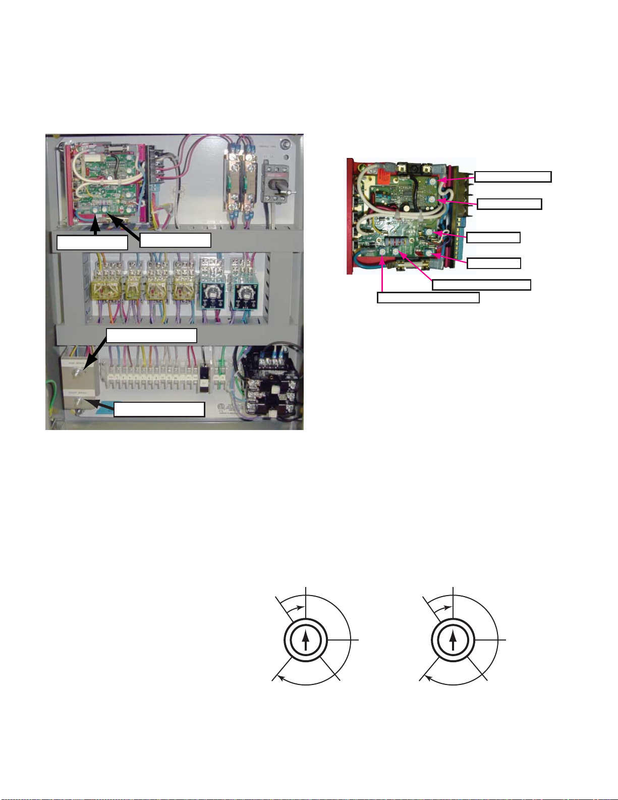
Step1:
With the mechanical disconnect disengaged and the
door free to move by hand, turn the power ON. Depress
"Open" push button. Does the Relay in the control box
labeled "O" light? If YES, proceed to step (2), if NO,
TURN POWER OFF and check the wiring from the
"OPEN" activation switch to the control box.
Step 2:
Is the operator rotating the proper direction to open the
door? If NO, turn off power to the operator control box.
Switch the motor wires typically labeled M1 & M2 or A1
& A2, located at the bottom of the control box. Turn the
power back on and check for proper rotation.
F. PRELIMINARY ROTARY LIMIT SWITCH
ADJUSTMENT
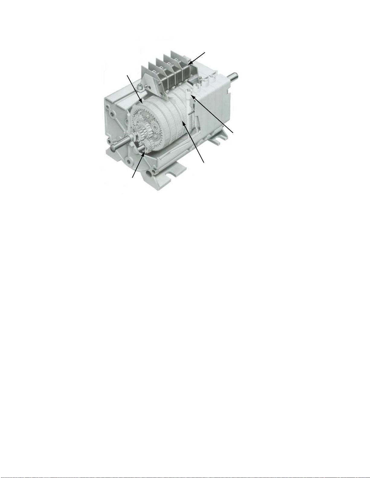
(1) DESCRIPTION: The rotary limit switch is designed
to accurately control the end limits of the door travel
provided by the electric operator as well as the activation
point and duration of the creep mode. The limit switch
input shaft drives a set of planetary gears which in
turn drives a set of nylon cams (See Figure 2). Each
precision limit switch unit is actuated by its individual
nylon cam. The cam rotate as the operator travels the
door back and forth. The cam contact the electrical
snap switches to either stop the travel of the operator or
initiate the creep modes. The limit switch has 4 switches.
(a) LSO = Limit Switch Open
This limit shuts off the electric operator when the
door reaches the full open position.
(b) LSC = Limit Switch Close
This limit shuts off the operator when the door
has reaches the full closed position.
(c) LSCO = Limit Switch Creep Open
This limit activates the creep mode during the
end of open cycle. When the limit switch is
actuated the door travels in the open direction at
a reduced speed.
(d) LSCC = Limit Switch Creep Close
This limit activates the creep mode during the
closing cycle. When this limit switch is actuated
the door travels in the closed direction at a
reduced speed.
To adjust each individual limit switch, turn the screw
adjustment for each specific limit switch. Note that
depending upon the handing of the operator the cams
travel from either the clockwise or counterclockwise
direction to activate the appropriate snap switches.
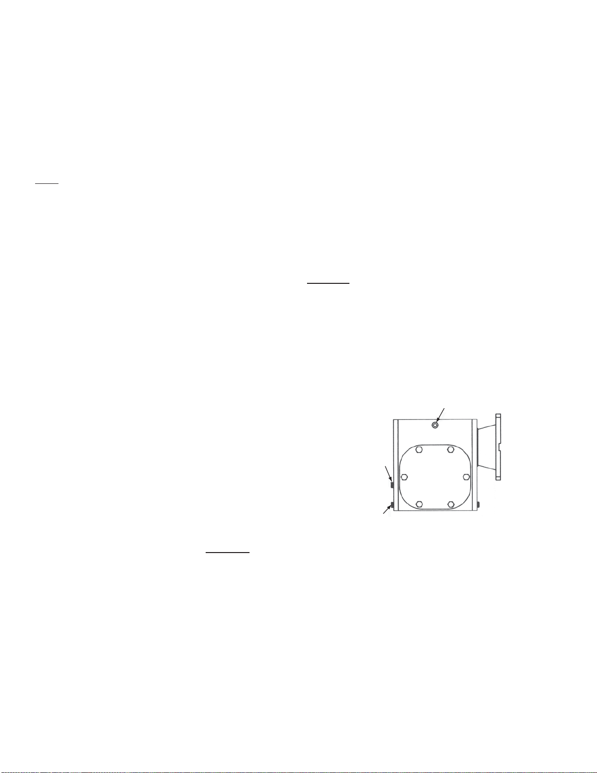
(2) PREPARATION FOR ADJUSTMENT:
(a) Disconnect the Electrical Power Supply to the
Operator Control Box.
(b) Unscrew limit switch cover and expose assembly.
(3) ROUGH ADJUSTMENT:
(a) Manually slide the door in the open direction
and note the direction the LSO cam lobe is
traveling. Clockwise or counterclockwise?
(b) Manually slide the door to approximately 6" from
the full open position.
(c) Adjust the LSO cam adjuster until the cam
contacts the electrical snap switch from the
same direction and you hear it click.
(d) Manually slide the door towards the closed
direction and back towards the open direction.
The snap switch should click when the door gets
approx. 6" from the full open position.
(e) Position the door approx. 12" from the full open
position.
(f) Turn the LSCO cam adjusting screw until the cam
contacts the electrical snap switch from the same
direction as the LSO switch and you hear it click.
Note: This cam is longer and the operator shall
only travel in closed creep mode while this cam is
depressing the snap switch.
(g) Repeat Step (d). The LSCO the snap switch
should click when the door gets approx. 12" from
the full open position.
(h) Manually slide the door to approximately 6" from
the full closed position.
(i) Turn the LSC cam adjusting screw until the cam
contacts the electrical snap switch from
the opposite direction and you hear it click.
(j) Manually slide the door towards the open
direction and back towards the closed direction.
The snap switch should click when the door gets
approx. 6" from the full closed position.
(k) Position the door approx. 12" from the fully
closed position.
(l) Turn the LSCO cam adjusting screw until the cam
contacts the electrical snap switch from the same
direction as the LSC switch and you hear it click.
Note: This cam is longer and the operator shall
only travel in open creep mode while the cam is
depressing the snap switch.
(m) Repeat step (j) LSCO the snap switch should
click when the door gets approx. 12" from the full
open position.
(n) Move the door back and forth noting that the
proper snap switches are being contacted from
the proper direction at the proper time.
Crown Industrial Operators • 213 Michelle Ct. • So. San Francisco, Ca 94080-6202
Phone: (650) 952-5150 • Fax: (650) 873-1495
G-2001 3

G. VENT PLUG
Remove the 1/2" NPT steel pipe plug located nearest
the top of the gearbox and replace it with the plastic vent
plug provided with the operator (See Figure 16).
H. SETTING THE CLUTCH
(1) The purpose of the clutch is to protect the equipment
from shock loads that might be introduced into the
system. Under normal operation the clutch will not slip.
Therefore, the clutch should be adjusted to a sufficient
torque that will allow the operator to start and stop the
door without any slipping. Keep in mind also that the
clutch should not be so tight that it cannot slip under
excessive loads.
(2) The magnetic clutch has an adjustable torque
output feature. The output is controlled by rotating the
electronic clutch controller located in the main control
panel. When the voltage is reduced the clutch torque
characteristics are de-rated. The clutch should be set
with just enough power to move the door. Turning off the
power to the operator will power off the clutch controller
and will allow the door to be operated manually. As an
additional option, a magnetic lock with battery backup
can be used to prevent manual operation of the door
during power failure.
I. SETTING RUN SPEED AND CREEP SPEED
Inside the operator control box locate the run speed
and creep speed potentiometers (Figure 4). The
potentiometers control the run and creep speeds of the
operator. Turning them clockwise increases the rate of
travel.
(a) Carefully turn the run speed potentiometer all the
way counterclockwise and then back clockwise
approx. 135 degrees.
(b) Carefully turn the creep speed potentiometer
all the way counterclockwise and then back
clockwise approx. 20 degrees.
(c) Release the drive chain latch and affix it so that
it cannot reattach automatically. Note the location
of the long link, this is where the chain latch
attaches to the drive chain.
(d) Turn ON the power to the operator controller.
(e) Actuate a push button to run the operator.
The operator should travel the door in the
appropriate direction, slow down and creep into
approximately the full open or closed position.
(f) Reconnect chain latch to long link. Operate the
door open and closed.
(g) To increase or decrease the travel speed in
both run and creep speed adjust the appropriate
potentiometer clockwise to increase the speed
and counterclockwise to decrease the speed.
(h) Set the run and creep speeds to the desired
levels.
U.L. recognized snap-action
switches. Supplied as
SPDT, DPDT optional.
Rotary Cam Limit
Switch Assembly
SRLS51-( )-SP4
Plastic planetary gear
reduction stages. Sun gear
is input, ring gear is
stationary, planet carrier is
output. No lubrication.
17.5
29
75
Independent cam
adjusting screw with
self-locking adjustment.
Gear switching stages are
same as gear reduction
stages except cam is on
planet carrier. Sun gears
connected in parallel.
Primary gear stages yield
mulitiplier for
input/cam shaft ratio.
Figure 2.
Crown Industrial Operators • 213 Michelle Ct. • So. San Francisco, Ca 94080-6202
Phone: (650) 952-5150 • Fax: (650) 873-1495

J. DC DRIVE SETTINGS
(1) ACCEL/DECEL
The DC drive located inside the operator control box has
separate potentiometers for both ACCEL and DECEL.
These are typically set at the factory but are field
adjustable. Depending upon the size and weight of a
specific door, it may be necessary to field adjust the
ACCEL & DECEL to allow for the operator to smoothly
ramp up to full run speed and smoothly ramp down to
creep speed (See Figure 4, 5 & 6).
The ACCEL potentiometer controls the acceleration
from 0 to the run speed setting. The minimum ACCEL
setting should be 1 second.
The DECEL potentiometer controls the deceleration rate
from run speed to creep speed.
To adjust either the ACCEL or DECEL, turn the
potentiometer clockwise to increase the duration of time
to accelerate or decelerate, and counterclockwise to
decrease the time. The setting must take into account
the run speed, weight of the door and the length of the
creep mode. The faster the travel and/or the heavier the
door the longer the transition time should be.
DO NOT ATTEMPT TO ADJUST THE OTHER
POTENTIOMETERS ON THE DC CONTROL BOARD.
THEY ARE FACTORY SET & ADJUSTMENTS WILL
DAMAGE THE UNIT AND VOID THE WARRANTY.
(2) MAXIMUM SPEED - factory set, do not adjust without
consulting factory
(3) MINIMUM SPEED - factory set, do not adjust without
consulting factory
(4) CURRENT LIMIT - factory set, do not adjust without
consulting factory
(5) IR COMPENSATION - factory set, do not adjust
without consulting factory
CREEP SPEED POTENTIOMETER
RUN SPEED POTENTIOMETER
DECEL POTENTIOMETER
ACCEL POTENTIOMETER
ACCEL POTENTIOMETER
DECEL POTENTIOMETER
MAX. SPEED
MIN. SPEED
CURRENT LIMIT
IR COMPENSATION
Figure 4.
Figure 5.
RAPID
.2 SEC.
5 SEC.
SLOW
10 SEC.
8 SEC.
RAPID
.2 SEC.
5 SEC.
SLOW
10 SEC.
8 SEC.
FACTORY SETTING 1 SEC.
The following procedure, presented in order
of adjustment sequence, should be used
when re-adjusting all trimpot functions:
CAUTION!
[PM motors only]. Adjusting the accel
time below .5 seconds increases
inrush current. It may be necessary
to measure the peak inrush current
and consult with motor manufacturer
since field magnet demagnetization
may occur. ACCEL
FACTORY SETTING 1 SEC.
DECEL
Figure 6.
Crown Industrial Operators • 213 Michelle Ct. • So. San Francisco, Ca 94080-6202
Phone: (650) 952-5150 • Fax: (650) 873-1495

K. FINAL ROTARY LIMIT SWITCH ADJUSTMENT
After the run speed, creep speed and ACCEL & DECEL
have been adjusted, the final limit switch settings can be
made.
(a) Actuate the operator controls and adjust the
rotary limit switches (LSO & LSC) to stop the
door in the full open and closed positions.
(b) Actuate the operator and adjust the rotary limit
switches (LSCO & LSCC) to initiate the creep
mode at the desired time. Keep in mind that the
operator only travels in creep mode as long as
the cam lobe is depressing the snap switch.
Note: The length of time the operator is running in creep
mode must be long enough to allow for it to dynamically
brake from run speed to creep speed plus the desired
length of time the operator is traveling under creep
mode. If the DECEL time is set for too long, the creep
mode may be adversely affected.
(c) After adjusting LSCO & LSCC check the travel of
the door. LSC & LSO may need to be re-adjusted.
(d) Activate the operator to open and close the door
several times and fine tune the limit switch
settings.
(e) Close limit switch cover and tighten down screw
clamp.
(f) Periodically the limit switches may require
adjustment. This is especially evident during the
initial few weeks after start up due to chain
stretch and wear in.
L. FINAL ADJUSTMENTS & CHECKS
(1) Make a final check of operator, Chain Tensioner,
sliding door hardware, sag roller(s) and idlers. It is
extremely important that the operator be run several
times to check chain alignment. Make corrections as
needed.
3. MAINTENANCE
A. GENERAL
To insure that the electric operator is ready for operation
at all times, it must be inspected systematically which will
preclude serious damage or failure. Proper adjustment
and lubrication must be maintained and checked as
recommended below.
B. LUBRICATION
(1) LUBRICATION FOR GEARMOTOR
(a) Figure 16 shows the proper location of vent, oil
level, and drain plugs.
(b) The drive unit is pre-lubricated and shipped with
Mobil "SHC 634" synthetic lubricant. This oil is a lifetime
lubricant rated for operation in ambient temperatures
ranging from -40°F to +125°F.
(2) Every 900 cycles, where one cycle consists of
opening and closing of the door, or every 3 months
whichever comes first, clean and lubricate the chain with
a SAE lubricant as required for ambient temperature.
C. PREVENTIVE MAINTENANCE
To prevent damage or improper operation, the following
inspections should be let made at least EVERY 6
MONTHS.
(1) Check oil level by removing the oil level plug. Oil
should be up to the bottom of the plug hole.
(2) Check tension of chain.
(3) Check all electrical components and wiring for
tightness.
(4) Check clutch to see that it doesn’t slip under
normal operation.
(5) Check all bolts and nuts for tightness.
VENT PLUG
OIL LEVEL
PLUG
DRAIN
PLUG
Figure 7.
A. TO ORDER REPLACEMENT PARTS
(1) SEND IN SERIAL NUMBER OF ELECTRIC
OPERATOR.
(2) SPECIFY the number of pieces needed.
(3) Order by part number and name of part.
(4) State whether to ship by freight, truck, parcel
post, or air express.
(5) State whether transportation charges are to be
prepaid or collect.
(6) Give name and address of the person or
company to whom the parts are to be shipped.
(7) Give name and address of person or company to
whom the invoices to be sent.
4. PARTS
Crown Industrial Operators • 213 Michelle Ct. • So. San Francisco, Ca 94080-6202
Phone: (650) 952-5150 • Fax: (650) 873-1495

Crown Industrial Operators
213 Michelle Court
So. San Francisco, CA 94080
Phone (650) 952-5150
Fax (650) 873-1495
website: www.crown-industrial.com
GUARANTEE
If, within a period of one year from date of shipment, any part of a CIO
Electric "Aut-o-doR" Operator is found defective due to poor materials
or workmanship, new parts will be furnished free of charge F.O.B.
manufacturer’s plant, providing the equipment has been given normal
and proper usage, lubrication, and maintenance and is still the property
of the original purchaser and/or part of the original installation. THIS
WARRANTY IS GIVEN IN LIEU OF ALL OTHER WARRANTIES,
EXPRESSED OR IMPLIED, AND THE MANUFACTURER MAKES
NO IMPLIED WARRANTY OF MERCHANTABILITY BEYOND THE
EXPRESSED TERMS HEREOF. MANUFACTURER’S LIABILITY FOR
DAMAGES, INCLUDING CONSEQUENTIAL DAMAGES RESULTING
FROM ANY SUCH DEFECTIVE PRODUCT IS STRICTLY LIMITED TO
THE DELIVERY OF NEW PARTS, AS SET FORTH ABOVE.
Operator Serial Number _______________________________ H.P. ____________________________________
Supplied on Crown Industrial Operators Order Number __________________________________________________
Power Supply ____________ Volts ___________ Hz _______________ Phase __________________________
Installed At _______________________________ Date _______________________________________________
Notes ________________________________________________________________________________________
________________________________________________________________________________________
________________________________________________________________________________________
________________________________________________________________________________________
________________________________________________________________________________________
MAINTENANCE INFORMATION
(To Be Filled Out By User)
G-2001 Crown Industrial Operators • 213 Michelle Ct. • So. San Francisco, Ca 94080-6202
Phone: (650) 952-5150 • Fax: (650) 873-1495
This manual suits for next models
1
Table of contents
Other Crown Door Opening System manuals