Crown CT44059 User manual


2
Content / Contenido / Содержание / Зміст / Мазмұны /
English
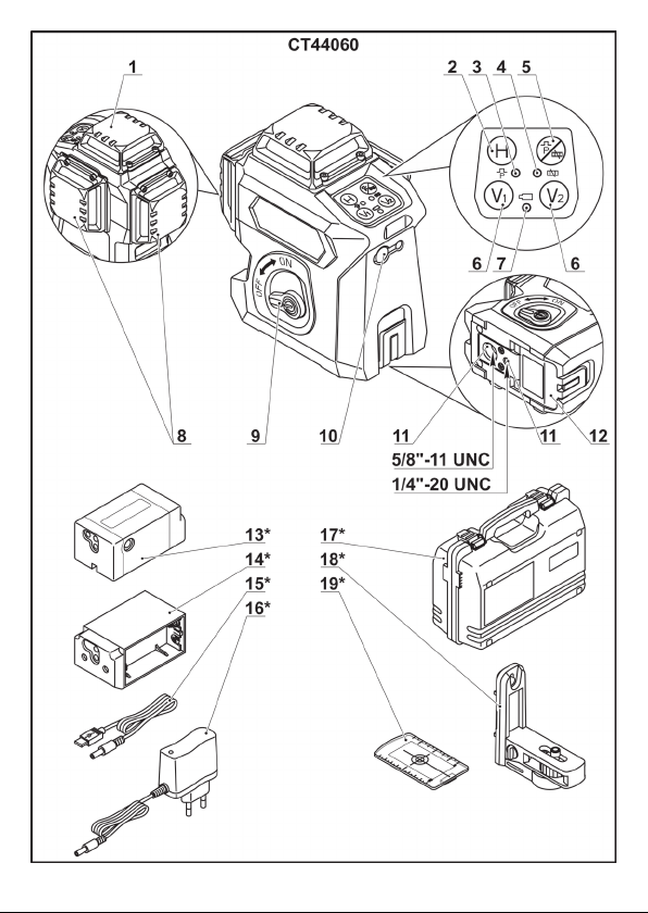
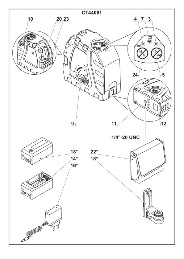
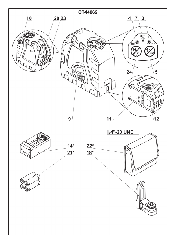
Explanatory drawings �������������������������������������������������������������������������������������������� pages
General safety rules, instructions manual ������������������������������������������������������������� pages
3 - 14
15 - 21
Español
Dibujos explicativos �������������������������������������������������������������������������������������������� páginas
Recomendaciones generales de seguridad, manual de instrucciones �������������� páginas
3 - 14
22 - 28
Русский
Пояснительные рисунки �������������������������������������������������������������������������������� страницы
Общие указания по ТБ, инструкция по эксплуатации ��������������������������������� страницы
3 - 14
29 - 36
Украïнська
Пояснювальні малюнки ����������������������������������������������������������������������������������� сторінки
Загальні вказівки по ТБ, iнструкція з експлуатації ����������������������������������������� сторінки
3 - 14
37 - 43
Қазақ тілі
Түсіндіргіш әлеміштер ���������������������������������������������������������������������������������������� беттер
Жалпы қауіпсіздік жөніндегі ұсыныстар, пайдалану нұсқаулығы ������������������������ беттер
3 - 14
44 - 50
������������������������������������������������������������������������������������������������������
��������������������������������������������������������������������������
3 - 14
51 - 56
���������������������������������������������������������������������������������������������������
����������������������������������������������������������������
3 - 14
57 - 62

3

4

5

6

7

8

9

10

11

12

13

14

15
English
Technical data
Line laser CT44059 CT44060 CT44061 CT44062 CT44065
Appliance code 242325 242332 242349 242356 242387
Projected beams 1V
1H(360°)
2V(360°)
1H(360°)
1V
1H
1V
1H
2V(360°)
1H(360°)
Max. working range [m] 30 30 30 15 15
Levelling accuracy:
- horizontal beam ±3 mm at 10 m ±3 mm at 10 m ±3 mm at 10 m ±3 mm at 10 m ±3 mm at 10 m
- vertical beam ±3 mm at 10 m ±3 mm at 10 m ±3 mm at 10 m ±3 mm at 10 m ±3 mm at 10 m
Self-leveling time [s] ≤3 ≤3 ≤3 ≤3 ≤3
Self-leveling range ±3° ±3° ±3° ±3° ±3°
Laser class II II II II II
Laser type [nm] 515 515 515 635 635
Battery type 4 x AA 7,4 V, Li-Ion 7,4 V, Li-Ion 4 x AA 7,4 V, Li-Ion
Thread for tripod 1/4"-20 UNC 1/4"-20 UNC /
5/8"-11 UNC 1/4"-20 UNC 1/4"-20 UNC 1/4"-20 UNC /
5/8"-11 UNC
Operating temperature range [°C] -10 ��� +45 -10 ��� +45 -10 ��� +45 -10 ��� +45 -10 ��� +45
Storage temperature range [°C] -20 ��� +70 -20 ��� +70 -20 ��� +70 -20 ��� +70 -20 ��� +70
Weight [kg]
[lb] 0,6
1�32
0,88
1�94
0,57
1�26
0,57
1�26
0,88
1�94
* V - vertical plane, H - horizontal plane.

16
English
Declaration of conformity
We declare under our sole responsibility that the
product described under "Technical data" is in
conformity with all relevant provisions of the di-
rectives 2006/42/EC including their amendments
and complies with the following standards:
EN 60825-1:2007,
EN 61010-1:2010�
Certication Wu Cunzhen
manager
Merit Link International AG
Stabio, Switzerland, 21�01�2021
General safety rules
WARNING - To reduce the risk of
injury, user must read instruction
manual!
ATTENTION! Before using the ap-
pliance for the rst time, read this
manual carefully and follow all its
recommendations and rules.
Keep the manual for future reference or for the
next owner.
•Before using, check the appliance housing
integrity; in case of any damages the appliance
must not be used�
Do not direct a laser beam at people or
animals, and do not look at a straight
or reected laser beam. A laser beam
can blind people, cause an accident
or damage eyes� It is strictly forbidden to look at
the laser beam through optical appliances (bin-
oculars, telescopes, etc�), this can cause damage
to the retina�
•Do not operate the appliance in atmospheres
containing explosive gases, dust or vapours�
•When working be aware of the factors which
may cause wrong measurement results:
•contamination of laser emitter window;
•measurement through transparent objects
(windows, aquariums, etc�);
•measurement on reective surfaces (mir-
rors, polished metal surfaces, etc�);
•presence of steam, dust, smoke, etc� in
the air�
•Do not expose the appliance to moisture, and
do not allow moisture enter the appliance� Do not
immerse the appliance into liquid�
•Do not drop or knock the appliance�
•Protect the appliance against electromagnetic
elds (for example, elds from electric arc welding
or induction heaters)�
•In case of sudden changes in ambient tem-
perature, do not use the appliance for at least 30
minutes�
•Do not leave the appliance near objects with
high temperature�
Battery tool use and care
•Recharge only with the charger specied
by the manufacturer. A charger that is suitable
for one type of battery pack may create a risk of
re when used with another battery pack.
•Use the appliance only with a suitable battery
pack. Use of other battery types may cause injuries
and re.
•Under abusive conditions, liquid may be
ejected from the battery; avoid contact. If con-
tact accidentally occurs, ush with water. If
liquid contacts eyes, additionally seek medical
help. Liquid ejected from the battery may cause
irritation or burns�
•Do not open the battery. Danger of circuit�
•In case of damage and improper use of
the battery, vapors may be emitted. Provide
for fresh air and seek medical help in case of
complaints. The vapors can irritate the respira-
tory system�
•When the battery is defective, liquid can
escape and come into contact with adjacent
components� Check any parts concerned� Clean
such parts or replace them, if required�
•Protect the battery against heat, e.g., also
against continuous sun irradiation and re.
There is danger of explosion�
•Protect the battery charger from rain and
moisture. The penetration of water in a battery
charger increases the risk of electric shock�
•Do not charge other batteries. The battery
charger is suitable only for charging lithium ion
batteries within the listed voltage range� Other-
wise there is danger of re and explosion.
•Keep the battery charger clean. Contamina-
tion may cause the danger of electric shock�
•Check the battery charger, cable and plug
each time before using. Do not use the bat-
tery charger when defects are detected. Do

17
English
not open the battery charger yourself and
have it repaired only by qualied personnel
using original spare parts. Damaged battery
chargers, cables and plugs increase the risk of
electric shock�
•Do not operate the battery charger on easily
inammable surfaces (e.g., paper, textiles, etc.)
or in combustible environments. There is danger
of re due to the heating of the battery charger dur-
ing charging�
Appliance maintenance
Maintenance of your appliance must be per-
formed by qualied personnel using the recom-
mended spare parts� This ensures that the safety
of your appliance will be preserved�
Symbols used in the manual
Following symbols are used in the operation
manual, please remember their meanings� Cor-
rect interpretation of the symbols will allow correct
and safe use of the appliance�
Symbol Meaning
Read all safety regulations and
instructions�
Caution! Laser radiation�
Movement direction�
Rotation direction�
Locked�
Unlocked�
A sign certifying that the product
complies with essential require-
ments of the EU directives and
harmonized EU standards�
Symbol Meaning
Attention� Important�
Useful information�
Do not dispose of the appliance in
a domestic waste container�
Intended use
Line laser is intended to draw and / or control hori-
zontal, vertical and inclined lines�
[CT44059, CT44060, CT44065]
Laser beams are projected at 360°, reecting
vertical or horizontal planes, or its intersection�
This expands the application eld of the device
and makes the performance of certain work types
more convenient�
Components
1 Protective cover of the horizontal laser beam
emitter
2 Horizontal laser beam on / off switch
3 Indicator "Outdoor mode"
4 Indicator "Inclined lines marking"
5 Button "Outdoor mode / inclined lines mark-
ing"
6 Vertical laser beam on / off switch
7 Power indicator
8 Protective cover of the vertical laser beam
emitter
9 Laser head position lock
10 Socket for power unit connector
11 Threaded hole for tripod mounting
12 Battery case cover
13 Battery *
14 Housing for installing batteries AA-type *
15 USB cable *
16 Charger *
17 Case *
18 Universal holder *
19 Laser target plate *

18
English
20 Vertical emitter window
21 Battery (AA-type) *
22 Carrying bag *
23 Horizontal emitter window
24 Laser beams on / off switch
25 Mounting screw *
26 Locking handle *
27 Carriage *
28 Magnet *
29 Tripod *
30 Charger indicator *
31 Socket for charger connection *
* Optional extra
Not all of the accessories illustrated or de-
scribed are included as standard delivery.
Installation / regulation
Do not draw up the fastening ele-
ments too tight to avoid damaging
the thread.
Mounting / dismantling / adjustment
of some elements is similar for all
appliance models. In this case no
particular appliance model is indi-
cated in the explanatory drawing.
Battery installation (see g. 1-2)
•Install the batteries 21 (AA-type, 4 pcs�) in
the housing 14, as shown onto g. 1. Caution:
during installation of batteries 21 in the hous-
ing 14, observe correct polarity (see g. 1).
•Open cover 8 (see g. 2.1).
•Install housing 14 (with installed batteries 21)
or battery 13 into appliance (see g. 2.2). Note:
the housing 14 and battery 13 are specially
shaped and can only be installed in one posi-
tion. Do not use excessive force when install-
ing the housing 14 or battery 13 to avoid dam-
aging them or appliance.
•Close cover 8 (see g. 2.3).
•Disassemble in the reverse sequence�
Universal holder (see g. 3-8)
•Install the appliance on the universal holder 18
using the mounting screw 25 as shown in g. 3-4.
•You can move the appliance mounted on the
universal holder 18 up or down (see g. 5).
•Rotate the locking handle 26 as shown
onto g. 5.1 - this will allow to move the car-
riage 27 up or down�
•Move the carriage 27 up or down (see
g. 5.2).
•Rotate the locking handle 26 as shown
onto g. 5.1 - this will lock the position of the
carriage 27�
•You can rotate the appliance mounted on the
universal holder 18 (see g. 6).
•Release mounting screw 25 (see
g. 3.2, 4.2).
•Rotate the appliance (see g. 6.1).
•Tighten mounting screw 25�
•For CT44059, CT44060, CT44065 - you can
move horizontally the appliance mounted on the
universal holder 18�
•Release mounting screw 25 (see
g. 3.2, 4.2).
•Move the appliance (see g. 6.2).
•Tighten mounting screw 25�
•You can install the universal holder 18 on fer-
romagnetic metal surfaces (elements of metal
structures, metal doors, frame structures for x-
ing drywall, etc�) using the magnets 28� In this
case, the appliance shall be installed in the posi-
tion shown in gure 7. Note: if you ip the ap-
pliance, the self-leveling system of the laser
head will be misguided.
•You can suspend the universal holder 18 as
shown in gure 8.1.
•You can install the universal holder 18 on a
tripod 29 with a mounting thread 1/4"-20 UNC
or 5/8"-11 UNC (see g. 8.2). Attention: tri-
pod 29 is not included in delivery set.
•If you hear an sound signal when the ap-
pliance is turned on and the laser beams are
ashing, the deviation of the appliance from the
horizontal plane is more than ±3°� In this case,
try changing the position of the appliance or re-
install it�
Battery charging
[CT44060, CT44061, CT44065]
Initial operating
The appliance is delivered with partial bat-
tery 13 charge. Fully charge the battery 13
before the rst use of the appliance.
If the power indicator 7 ashes
when the appliance is switched on,
it means that the battery 13 is dis-
charged and needs to be charged.

19
English
If are used batteries 21 (AA-type, 4 pcs.) - need
to replace them.
Charging (see g. 9-11)
•Remove the battery 13 from the appliance as
described above�
•Connect charger 16 to the mains (indicator 30
lights green, ready to charge)�
•Connect the plug of charger 16 to socket 31
(see g. 9-11). During charging indicator 30 lights
red� When charging is complete, indicator 30
lights green�
•When charging is complete, disconnect plug
of charger 16 from socket 31 and unplug charg-
er 16 from the mains�
During charging the battery 13 and
charger 16 may become hot - it is no
problem.
Switching on / off
When self-levelling is on
Switching on:
Set lock 9 to position as shown in g. 12.1. This
will unlock the suspension gear of the laser head
and turn power of laser beam� Also indicator 7
lighting on� If the appliance is positioned on the
inclined surface with an angle of more than ±3°,
you will hear an acoustic signal� You can switch
on and off the laser beams pressing on / off
switches 2, 6or 24�
Switching off:
Set lock 9 to position as shown in g. 12.2. This
will lock the suspension gear of the laser head,
turn power of laser off� Indicator 7goes out�
When self-levelling is off
Switching on:
Set lock 9 to position as shown in g. 12.2, then
press and release button 5� Indicator 7lighting
on, indicator 4will start blinking� Laser power is
now on, but the suspension gear of the laser head
is locked� No acoustic signals are given when the
appliance is inclined� You can switch on and off
the laser beams pressing on / off switches 2, 6
or 24�
Switching off:
Press and release button 5� Indicators 7and 4
goes out�
Design features
Powering the appliance from the mains (see
g. 13)
[CT44060, CT44065]
The appliance can powered from the mains�
Open the protective cover of socket 10 and con-
nect USB cable 15 to suitable power unit or USB
socket (see g. 13).
Laser head self-levelling system
Laser head self-levelling system makes laser
measurement possible, if the body of appliance
not in vertical position (inclination angle not ex-
ceeding ±3°)�
If maximum possible inclination angle is exceeded,
laser beams start blinking; the appliance gives an
acoustic signal� In this case, try changing the posi-
tion of the appliance or reinstall it�
Attention: if the appliance is moved
during use, lock the laser head during
storage and transportation (set lock 9
to the position shown in g. 12.2).
Circular planes projection
[CT44059, CT44060, CT44065]
When laser beams get on a cone-shaped wedge,
they are projected at 360°, forming a circular laser
plane� It allows you to make a circular level mark-
ing quickly and accurately without turning the ap-
pliance body� Moreover, the design features allow
you to install the appliance very close to the walls
or ceiling�
Outdoor mode
The button 5is designed to enable operation
in bright conditions (for example, in bright sun-
light)�
To work in this mode, it is recommended to use
a special laser glasses, laser target plate 19 (for
CT44060, CT44065 only) or laser receiver (not
supplied)�
•Turn on the appliance as described above�
•To turn on the outdoor mode, press and re-
lease the button 5� Indicator 3lighting on�
•To turn off the outdoor mode, press and re-
lease the button 5again� Indicator 3goes out�

20
English
Marking inclined lines (see g. 12.2)
Also the button 5disables the sound signal and
the blinking of laser beams (which signal that tilt
of appliance more than ±3°), this allows you to
mark inclined lines�
•Set lock 9 to position as shown in g. 12.2.
•To turn on this working mode, press and re-
lease the button 5� Indicator 7lighting on, indica-
tor 4will start blinking�
•To turn off this working mode, press and re-
lease the button 5� Indicators 7and 4goes out�
Universal holder (see g. 3-8)
The universal holder 18 allows you to install the
appliance on various objects, and to change the
position of the appliance easily, quickly and ac-
curately (move, turn)�
Working advice
Precision test
The appliance is ready for opera-
tion. The accuracy of the appliance
has been veried at the factory.
If measurement error exceeds maxi-
mum allowable variance during
the precision test, please contact
CROWN service centre.
Factors, inuencing appliance precision:
•ambient temperature, e�g�, temperature
difference which may take place with distance
from the ground� Temperature difference is
most considerable near ground surface, there-
fore it is recommended to use the tripod for
measurements in areas with length exceed-
ing 20 m;
•contamination of the laser emitter window�
Always check protective windows for contami-
nations before use and clean them if neces-
sary;
•measurement through transparent surfac-
es (windows, aquariums, etc�)� It is not recom-
mended to carry out such measurement;
•measurements on reective surfaces (mir-
rors, polished metal surfaces, etc�)� It is not
recommended to carry out such measure-
ment�
•presence of steam, dust, smoke, etc� in the
air� It is not recommended to carry out such
measurement;
•fall of the appliance or a heavy shock� In
this case it is recommended to perform a pre-
cision test� If maximum allowable variance is
exceeded, please contact CROWN service
centre�
General recommendation (see g. 12)
•Before starting work ensure that all measure-
ments will be carried out under suitable condi-
tions (see section "Factors, inuencing appliance
precision")�
•Place the appliance correctly as described
above and turn on it� If you hear a sound sig-
nal when turning on the appliance and the laser
beams blink, you have to re-position the appli-
ance, otherwise the measurement results will be
incorrect� Negligible horizontal misalignment can
be compensated with the laser head self-levelling
system (not exceeding ±3°)�
•After nishing work turn off the appliance as
described above (lock 9shall be in the position as
shown in g. 12.2 and laser beams must be off).
•It is recommended to put the appliance for
long-term storage and transportation into bag 22
(CT44059, CT44061, CT44062) or into case 17
(CT44060, CT44065)� Ensure that there are no
moisture drops on the appliance elements (if
necessary, wipe with a soft cloth), after that put
the appliance into bag 22 (CT44059, CT44061,
CT44062) or into case 17 (CT44060, CT44065)�
Marking inclined lines (see g. 12.2, 14)
In order to tilt the appliance, it's
recommended to mount it on a tri-
pod 29 that can tilt (tripod 29 is not
included in delivery set).
Attention! Do not mark horizontal
and vertical lines in this mode -
the position of the respective laser
beams may be incorrect (because
signal about impossibility of laser head self-
leveling is missing).
•Mount appliance on tripod 29 (not included in
delivery set)�
•Set lock 9 to position as shown in g. 12.2.
•Press and release the button 5� Indicator 7
lighting on, indicator 4will start blinking (see
g. 14.1).
•Gently tilt the appliance to the desired angle
(see g. 14.2).
This manual suits for next models
8
Table of contents
Languages:
Other Crown Laser Level manuals