manuals.online logo
Brands
  1. Home
  2. •
  3. Brands
  4. •
  5. Crown
  6. •
  7. Microphone
  8. •
  9. Crown PCC-170SWO User manual

Crown PCC-170SWO User manual

®
TOUCH
PCC-170SWO
Specifications
PHASE COHERENT
CARDIOID®MICROPHONE
Element: Electret condenser.
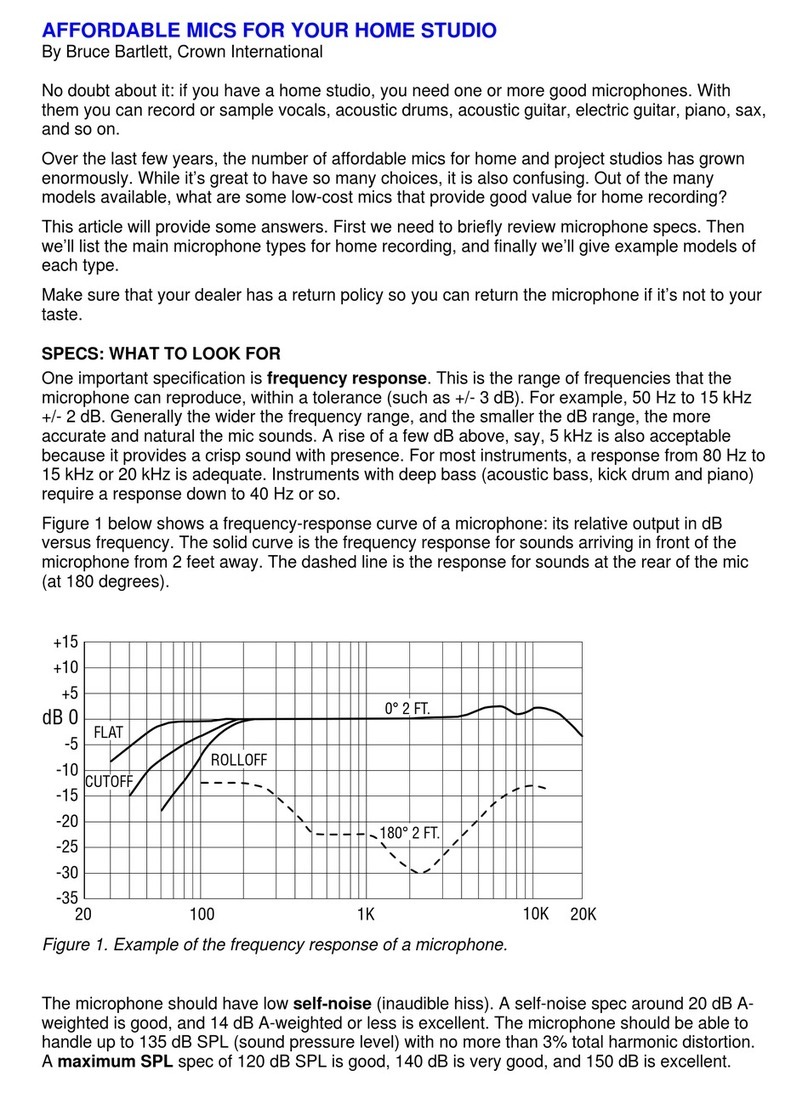
Frequency response (typical): 40 Hz to 20,000 Hz at 30
degrees incidence to surface. See Fig. 1.
Polar pattern: Half-supercardioid (supercardioid in the
hemisphere above the primary boundary). See
Figs. 2 and 3.
Impedance: 150 ohms, balanced. (Recommended load
impedance 1000 ohms or greater.)
Open-circuit sensitivity: 22 mV/Pa* (–33 dB re
1 V/Pa*).
Power sensitivity: –30.5 dB re 1 milliwatt/Pa*.
–125 dBm EIA rating.
Equivalent noise level (self noise): 22 dB SPL typical
(0 dB = .0002 dyne/cm2), A-weighted.
S/N ratio: 72 dB at 94 dB SPL.
Maximum SPL: 120 dB SPL produces 3% THD.
Polarity: Positive pressure on the diaphragm produces
positive voltage on pin 2 with respect to pin 3.
Operating voltage: Phantom power: 24 to 48 volts DC
positive on pins 2 and 3 with respect to pin 1.
Current drain: 4.5 mA nominal.
Cable: 15-foot, black, integral to microphone,
unterminated.
Off-attenuation: 70 dB at 1 kHz.
Maximum voltage and current which may be applied
to remote sensing contact-closure leads: 350 V,
200 mA. Small voltages are recommended; large
voltage changes may induce noise in audio output.
On-resistance: 7 to 10 ohms with the included 15-foot
cable.
Cable wiring: Shield: Audio shield.
Green: Audio in-polarity.
White: Audio opposite-polarity.
Red: Remote contact-closure sensing, +DC.
Black: Remote contact-closure sensing, –DC.
Materials: High-impact molded plastic and steel mesh
grille.
Finish: Satin black.
Net weight: 6 oz. (170 g).
Dimensions: See Fig. 4.
Optional accessories: Crown PH-1A phantom power
supply (one channel, battery or AC-adapter
powered). Crown PH-4B phantom power supply
(four channels, AC powered).
–20
–25
–30
–35
20 100 1K
+15
+10
+5
dB 0
–5
–10
–15
10K
BOOST
FLAT CUT
135°
BOOST
CUT
FRONT
REAR
-20
-15
-10
-5
-0
60° 90° 120°
150°
180°
0°
30°
200 Hz- 4 kHz
+
5
Fig. 1
Fig. 2
Fig. 3
Frequency Response
Frequency in Hz
Vertical Plane Polar Response
*1 pascal = 10 dynes/cm2= 10 microbars = 94 dB SPL.
FRONT
REAR
-20
-15
-10
-5
-0
dB
60°
90°
120°
150°180°
210°
240°
270°
300°
0°30°
330°
300 Hz-4 kHz
Horizontal Plane Polar Response
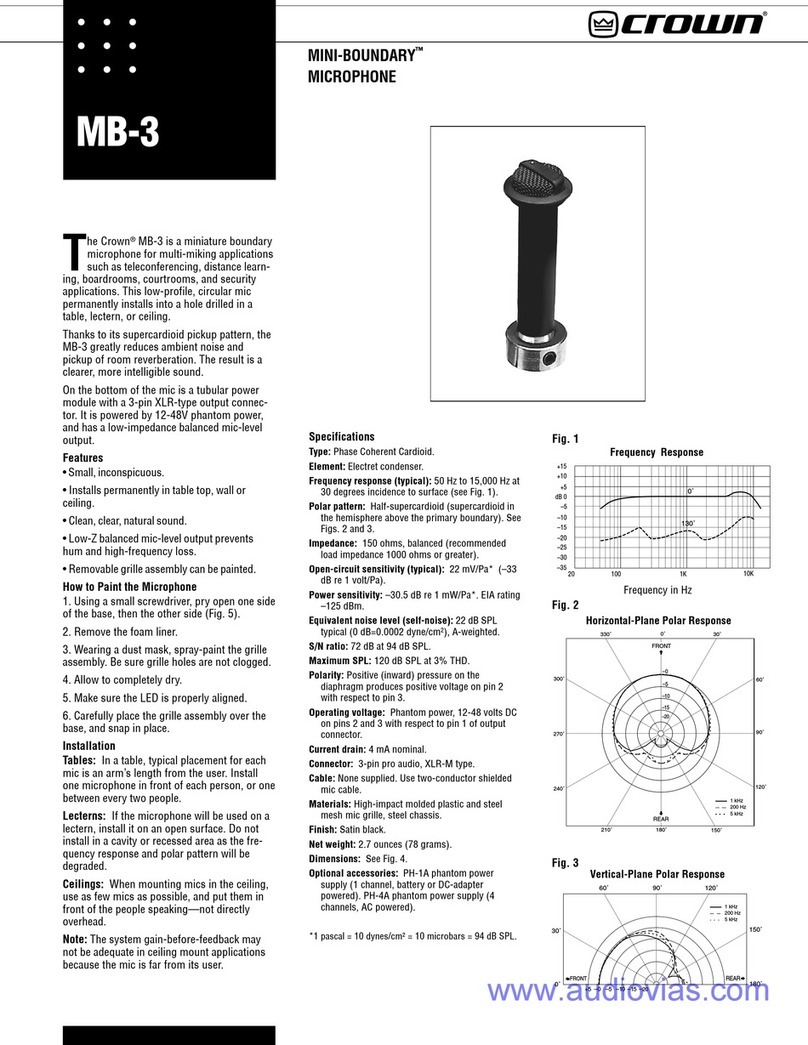
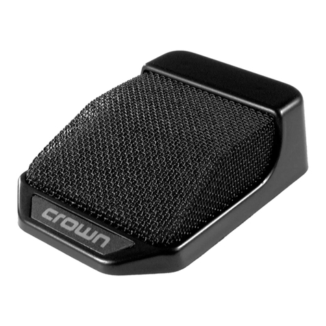
The Crown PCC-170SWO is a surface-
mounted supercardioid microphone for
distance learning or similar applications.
The user can turn the mic on and off by pressing
a membrane switch on the mic. A pair of extra
leads in the mic cable allows remote sensing of
the switch closure. In a typical distance-learning
application, a video camera would track to the
person who switched on the microphone.
The mic includes a bass-tilt switch, which lets
the user tailor the low-end response for particu-
lar applications. A high-frequency adjust is also
provided.
The membrane switch can be configured for
touch on/off, momentary on, or momentary off
operation. This configuration is set by a bottom-
mounted DIP switch. A high-intensity LED lights
when the unit is on.
The mic can be set to be always on. In this
mode, the switch only activates the remote
sensing and LED. This is useful when using an
external gated mixer (automatic mixer).
Remote sensing is done by a patented opto-
coupled MOS switching circuit. At the remote-
sensing leads, the resistance goes low when the
mic is on. The microphone is attenuated 70 dB
when the switch is off.
How to Set the Bass Tilt Switch
On the bottom of the microphone is a BASS-TILT
switch with three positions: FLAT, CUT, and
BOOST. It adjusts the low-frequency response as
shown in Fig. 1.
•The FLAT position provides a flat low-frequency
response, (normal operation). The mic is
shipped from the factory in the flat position.
•The CUT position rolls off the bass, useful in
noisy or boomy surroundings.
•The BOOST position boosts the bass for a
more natural sound when the mic is used on a
small surface such as a lectern.
You can also adjust the high-frequency re-
sponse. Insert a small screwdriver into the hole
labeled “HF ADJ”on the bottom of the mic.
How to Configure the Membrane Switch
The membrane switch can be programmed to
work three ways:
1. Touch on/off. Touch the switch to turn on the
mic; touch it again to turn off the mic.
2. Momentary on. Touch and hold the switch to
momentarily turn on the mic. Release the switch
to turn the mic back off.
3. Momentary off. Touch and hold the switch to
momentarily turn off the mic. Release the switch
to turn the mic back on. This option serves as a
cough button or privacy button.
www.audiovias.com
Microphone Warranty
Crown International, Inc.
P.O. Box 1000
Elkhart, IN 46515-1000
TEL: 219-294-8000
FAX: 219-294-8FAX
After choosing the option you prefer, set the DIP
switches according to the label on the bottom of
the microphone (see Fig. 5). The LED in the
microphone housing will light when the mic is
on.
If you want the mic to be continuously on (so
you can gate it on and off externally), set the DIP
switch to “DISABLE MIC GATING.”
Installation
Typical placement for each microphone is at
arm's length from the user. Either place one
microphone in front of each person or one
between every two people. The front of the
microphone is indicated by an arrow on the
bottom of the base plate.
If the microphone is used on a lectern, place it
on an open surface, not in a cavity. Otherwise
the frequency response and polar pattern will be
degraded.
Solder the shield, green and white leads to an
XLR type connector, shield to pin 1, green to 2,
white to 3. Plug this connector into the input of a
phantom-power supply such as a Crown PH-4B.
For each channel of the phantom-power supply,
connect the output to a mixer mic input. Or if
your mixer has phantom power built in, connect
each mic cable directly to a mixer mic input.
The PCC includes two keyhole slots in its base to
accept mounting screws. To screw the PCC to a
table top, follow this procedure:
®
1.6"
PCC-170SWO
Specifications subject to change without prior
notice.
Crown®, PCC®and Phase Coherent Cardioid®are
registered trademarks of Crown International, Inc.
©2000 Crown International, Inc.
Sample circuit for remote sensing. 4/00 101793-3
3.4"
8.6 cm
.900"
2.3 cm
4.84"
12.3 cm
TOUCH
9V
MIC
AUDIO +
AUDIO -
WHT
SHIELD
2K
BLK
GRN
RED
+
5
4
3
1
2
+DC
-DC
Fig. 6
TOUCH
ON/OFF
MOM OFF
MOM ON
HF ADJ
CUT OUT FOR
PERMANENT
INSTALLATION
SWITCH FUNCTION
DIP SWITCH POS
MADE IN USA
MICROPHONE FRONT
1718 W. Mishawaka Road, Elkhart, IN 46517
(219) 294-8000
®
BASS TILT
BOOST
FLAT
CUT
.480"
1.21 cm
+
.900"
2.3 cm
2.200"
5.58 cm
+
PCC-170SWO
Phase Coherent Cardioid
DISABLE
MIC
GATING
Fig. 4 Fig. 5
Fig. 6
Dimensions are to outside of plastic housing.
1. Punch out the keyholes marked on the label
underneath the base plate (use a razor blade,
small screwdriver, etc.).
2. Using the template (Fig. 6), mark the location
of two holes in the table where you want to
mount the mic. These holes are 1.6-inch (4.064
cm) apart, center-to-center.
3. Screw two #8 woodscrews (.270" dia. head)
into the table at the locations you marked.
4. Loosen the screws enough to receive the mic
and to hold it with a friction fit.
Operation
Press near the center of the switch. The micro-
phone will switch on or off according to how you
set the DIP switches. When the mic is on, the
LED in the housing is lit.
If you set the DIP switch to “DISABLE MIC
GATING,”the mic is always on. Pressing the
switch will light the LED and activate remote
sensing.
The contact-closure leads (red and black) pro-
vide remote sensing of mic attenuation. Switch
closed (low resistance) is mic ON. Switch open
(high resistance) is mic OFF.
To detect when the mic is on, apply a small
voltage to the remote sensing leads (Fig. 7).
Apply +DC to the red lead and -DC to the black
lead. Large voltage and current may induce noise
into the audio output. Maximum switch voltage
and current are 350 V, 200 mA. On-resistance is
7 to 10 ohms with the included 15-foot cable.
Warranty
Crown professional microphones are guaranteed
unconditionally against malfunction from any
cause for a period of three years from date of
original purchase. Please refer to the enclosed
full warranty sheet for more detail.
Service
If the microphone does not function properly,
replace or repair mic cables and connectors,
check the power supply. If service is required,
return the microphone in its original packaging
to: Crown Service Department, Plant 2 SW,
1718 W. Mishawaka Road, Elkhart, IN 46517.
For further assistance or technical support call
800.342.6939.
RL
(4.064 cm)
www.audiovias.com

Other Crown Microphone manuals

Crown 35246 User guide

Crown

Crown 35246 User guide

Crown CM-311AHS User manual

Crown

Crown CM-311AHS User manual

Crown DIFFEROID CM-311A Installation guide

Crown

Crown DIFFEROID CM-311A Installation guide

Crown PZM-6F User manual

Crown

Crown PZM-6F User manual

Crown PZM-30D User manual

Crown

Crown PZM-30D User manual

Crown LM-301A User manual

Crown

Crown LM-301A User manual

Crown CM-200A User guide

Crown

Crown CM-200A User guide

Crown PCC-130 User manual

Crown

Crown PCC-130 User manual

Crown SASS-P User manual

Crown

Crown SASS-P User manual

Crown CM-311AE Service manual

Crown

Crown CM-311AE Service manual

Crown LM-201 User manual

Crown

Crown LM-201 User manual

Crown CM-700 User manual

Crown

Crown CM-700 User manual

Crown CM-312AHS User manual

Crown

Crown CM-312AHS User manual

Crown CM-700 User manual

Crown

Crown CM-700 User manual

Crown MINI-BOUNDARY MB-3 User manual

Crown

Crown MINI-BOUNDARY MB-3 User manual

Crown DIFFEROID CM-311A User manual

Crown

Crown DIFFEROID CM-311A User manual

Crown PZM-30R User manual

Crown

Crown PZM-30R User manual

Crown CM-10 User manual

Crown

Crown CM-10 User manual

Crown PZM-30D User manual

Crown

Crown PZM-30D User manual

Crown LM-300A User manual

Crown

Crown LM-300A User manual

Crown PZM-11 User manual

Crown

Crown PZM-11 User manual

Crown Sound Grabber II User manual

Crown

Crown Sound Grabber II User manual

Crown CM-200A User guide

Crown

Crown CM-200A User guide

Crown PCC-170SW User manual

Crown

Crown PCC-170SW User manual

Popular Microphone manuals by other brands

Dynacord DPC 8015 owner's manual

Dynacord

Dynacord DPC 8015 owner's manual

Dynalink D 0985 operating instructions

Dynalink

Dynalink D 0985 operating instructions

Takstar TS-K201 user manual

Takstar

Takstar TS-K201 user manual

Chiayo DWR-2420 Operation manual

Chiayo

Chiayo DWR-2420 Operation manual

Sennheiser EM 500 G3 - 02-09 instruction manual

Sennheiser

Sennheiser EM 500 G3 - 02-09 instruction manual

Superlux PRA518 instructions

Superlux

Superlux PRA518 instructions

Vonyx WM552 instruction manual

Vonyx

Vonyx WM552 instruction manual

Shure ShurePlus MOTIV MV88 manual

Shure

Shure ShurePlus MOTIV MV88 manual

Power Dynamics WM62 instruction manual

Power Dynamics

Power Dynamics WM62 instruction manual

Audio Technica ES935S Installation and operation

Audio Technica

Audio Technica ES935S Installation and operation

Samson UB1 owner's manual

Samson

Samson UB1 owner's manual

Electro-Voice CH230 user manual

Electro-Voice

Electro-Voice CH230 user manual

AKG PERCEPTION 120 USB quick start guide

AKG

AKG PERCEPTION 120 USB quick start guide

Honeywell Notifier DVC MIC-1 Installation Document

Honeywell

Honeywell Notifier DVC MIC-1 Installation Document

Audio Technica BP4073 Specifications

Audio Technica

Audio Technica BP4073 Specifications

Azden SGM-2X instructions

Azden

Azden SGM-2X instructions

Televic Confidea Wireless Microphones quick guide

Televic

Televic Confidea Wireless Microphones quick guide

Omnitronic VRM-1000 PRO user manual

Omnitronic

Omnitronic VRM-1000 PRO user manual

manuals.online logo
manuals.online logoBrands
  • About & Mission
  • Contact us
  • Privacy Policy
  • Terms and Conditions

Copyright 2025 Manuals.Online. All Rights Reserved.