manuals.online logo
Brands
  1. Home
  2. •
  3. Brands
  4. •
  5. Chiayo
  6. •
  7. Microphone
  8. •
  9. Chiayo DWR-2420 User manual

Chiayo DWR-2420 User manual

DWR-2420
DWR-2410
2.4GHz Digital True Diversity / Diversity Wireless Microphone
ISO 9001
ISO 14001
OHSAS 18001
GREEN PRODUCT
Operation manual
ISO
14001
REGISTERED
INTERNATIONAL
OHSAS
18001
REGISTERED
INTERNATIONAL
-1-
Thank you for choosing CHIAYO digital wireless microphone system!
Our products are designed to last and for user friendly operation. Each system consists of:
1. a receiver
2. one or two handheld/belt-pack transmitter
3. a pair of antennas
4. a switching adaptor
5. an operation manual
For more details, please take a few moments to read this operating manual for thorough
understanding of the function and operation of both transmitter and receiver.
Parts and functions of DWR-2420 dual-channel receiver
Front panel
1. Power button
2. LCD display (channel 1)
3. Synchronization button (channel 1)
4. MENU/DOWN button (channel 1)
5. MENU/UP button (channel 1)
6. SET button (channel 1)
7. Volume control (channel 1)
8. LCD display (channel 2)
9. Synchronization button (channel 2)
10.MENU/DOWN button (channel 2)
11.MENU/UP button (channel 2)
12.SET button (channel 2)
13.Volume control (channel 2)
Rear panel
14.Antenna B socket (SMA type)
15.Balanced audio output (channel 2)
16.Balanced audio output (channel 1)
17.Unbalanced audio output (mixed)
18.Receiving mode switch
2CH (left): To use 2 transmitters in DIVERSITY mode.
1CH (right): To use 1 transmitter in TRUE DIVERSITY mode.
19.Antenna A socket (SMA type)
20.DC in
SETSYNC MIN MAX
VOLUME 1
SETSYNC MIN MAX
VOLUME 2POWER
DDiiggiittaallWWiirreelleessssRReecceeiivveerr
DDWWRR--22442200 C H
GRP FREQ CH.
RF AF
MHz
078
2478
C H
GRP FREQ CH.
RF AF
MHz
082
2482
1
2
3 4 5 6 7
8
910 11 12 13
ANT. B ANT. A DC IN
12V
MIX ED O UTMIC O U T 1
1.G
2.
3.
MIC O U T 2 DIVERSIT Y
1CH2CH
14 15 16 17 18 19 20
ISO 9001|ISO 14001|OHSAS 18001
-2-
Parts and functions of DWR-2410 single-channel receiver
Front panel
1. Power button
2. LCD display
3. Synchronization button
4. MENU/DOWN button
5. MENU/UP button
6. SET button
7. Volume control
Rear panel
8. Antenna B socket (SMA type)
9. Balanced audio output
10.Unbalanced audio output
11.Antenna A socket (SMA type)
12.DC in
SETSYNC MIN MAX
VOLUMEPOWER
DDiiggiittaallWWiirreelleessssRReecceeiivveerrDDWWRR--22441100
2
C H
GRP FREQ CH.
RF AF
MHz
082
2482
1 3 4 5 6 7
ANT. B ANT. A DC IN
12~15V
LINE OUTMIC O U T
1.G
2.
3.
8 9 10 11 12
-3-
Changing CHANNEL / FREQUENCY
1. Press-release ▲(UP) or ▼(DOWN) button
until the below channel icon appears.
2. Press and hold SET button until the channel
number flashes to denote readiness for
setting.
►
►
3. Press-release ▲(UP) or ▼(DOWN) button
to select a new channel.
4. After a channel is chosen, press SET button
to store the setting.
►
CHANNEL scanning
For an interference- free operation, a cleaner channel might be necessary if the current one
receives too much interference. Before scanning, the transmitter must be switched off.
1. Press-release ▲(UP) or ▼(DOWN) button
until the LCD displays
SER000
and below
frequency icon appears.
2. Press and hold SET button until
SER000
flashes to denote readiness for setting.
►
►
3. Press-release ▲(UP) or ▼(DOWN) button
to find and locate a clear, interference- free
channel.
4. After a channel is chosen, press SET button
to store the setting.
►
CH.
SETSYNC MIN MAX
VOLUME 1
SETSYNC MIN MAX
VOLUME 2POWER
DDiiggiittaall WWiirreelleessssRReecceeiivveerr
DDWWRR--22442200 C H
GRP FREQ CH.
RF AF
MHz
078
2478
C H
GRP FREQ CH.
RF AF
MHz
082
2482
C H
CH.
RF AF
MHz
0 8 2
2482
SETSYNC MIN MAX
VOLUME 1
SETSYNC MIN MAX
VOLUME 2POWER
DDiiggiittaall WWiirreelleessssRReecceeiivveerr
DDWWRR--22442200 C H
GRP FREQ CH.
RF AF
MHz
078
2478
C H
GRP FREQ CH.
RF AF
MHz
082
2482
C H
CH.
RF AF
MHz
0 8 2
2482
SETSYNC MIN MAX
VOLUME 1
SETSYNC MIN MAX
VOLUME 2POWER
DDiiggiittaall WWiirreelleessssRReecceeiivveerr
DDWWRR--22442200 C H
GRP FREQ CH.
RF AF
MHz
078
2478
C H
GRP FREQ CH.
RF AF
MHz
082
2482
CH
CH.
RF AF
MHz
0 7 2
2472
SETSYNC MIN MAX
VOLUME 1
SETSYNC MIN MAX
VOLUME 2POWER
DDiiggiittaall WWiirreelleessssRReecceeiivveerr
DDWWRR--22442200 C H
GRP FREQ CH.
RF AF
MHz
078
2478
C H
GRP FREQ CH.
RF AF
MHz
082
2482
FREQ
SETSYNC MIN MAX
VOLUME 1
SETSYNC MIN MAX
VOLUME 2POWER
DDiiggiittaall WWiirreelleessssRReecceeiivveerr
DDWWRR--22442200 C H
GRP FREQ CH.
RF AF
MHz
078
2478
C H
GRP FREQ CH.
RF AF
MHz
082
2482
C H
FREQ
RF AF
MHz
0 7 2
SER000
SETSYNC MIN MAX
VOLUME 1
SETSYNC MIN MAX
VOLUME 2POWER
DDiiggiittaall WWiirreelleessssRReecceeiivveerr
DDWWRR--22442200 C H
GRP FREQ CH.
RF AF
MHz
078
2478
C H
GRP FREQ CH.
RF AF
MHz
082
2482
C H
RF AF
0 7 2
SER000
SETSYNC MIN MAX
VOLUME 1
SETSYNC MIN MAX
VOLUME 2POWER
DDiiggiittaall WWiirreelleessssRReecceeiivveerr
DDWWRR--22442200 C H
GRP FREQ CH.
RF AF
MHz
078
2478
C H
GRP FREQ CH.
RF AF
MHz
082
2482
C H
RF AF
0 7 2
SER075
SETSYNC MIN MAX
VOLUME 1
SETSYNC MIN MAX
VOLUME 2POWER
DDiiggiittaall WWiirreelleessssRReecceeiivveerr
DDWWRR--22442200 C H
GRP FREQ CH.
RF AF
MHz
078
2478
C H
GRP FREQ CH.
RF AF
MHz
082
2482
ISO 9001|ISO 14001|OHSAS 18001
-4-
CHANNEL SYNCHRONIZING of the receiver and transmitter
1. Press and hold the transmitter’s
synchronizing button until LINK flashes on
the LCD.
2. Press and hold the receiver’s SYNC button
until the frequency icon appears. After
successful channel synchronizing, this icon
will disappear automatically.
►
►
CHANNEL GROUP setting
1. Press-release ▲(UP) or ▼(DOWN) button
until the below group icon appears.
2. Press and hold SET button until the group
number and the icon flash to denote
readiness for setting.
►
►
3. Press-release ▲(UP) or ▼(DOWN) button
to choose a channel group.
Group CH082 includes 82 selectable
frequencies from CH1 to CH82.
Group CH190 includes 190 selectable
frequencies from CH1 to CH190.
4. After a group is chosen, press SET button
to store the setting.
►
Receiver installation
1. For best operation, the receiver should be at least 1m
above the ground and 1m away from a wall or metal
surface to minimize reflections.
2. The transmitter should also be at least 1m away from a wall
or metal surface to minimize reflections. The transmitter
should also be at least 1m away from the receiver.
3. Keep antennas away from noise source such as motors,
automobiles, neon light as well as large metal objects.
FREQ
C H : 0 0 0
L I N K
SYNC
C H
FREQ CH.
RF AF
MHz
0 8 2
2482
GRP
GRP
SETSYNC MIN MAX
VOLUME 1
SETSYNC MIN MAX
VOLUME 2POWER
DDiiggiittaall WWiirreelleessssRReecceeiivveerr
DDWWRR--22442200 C H
GRP FREQ CH.
RF AF
MHz
078
2478
C H
GRP FREQ CH.
RF AF
MHz
082
2482
C H
GRP
RF AF
MHz
0 8 2
CH082
SETSYNC MIN MAX
VOLUME 1
SETSYNC MIN MAX
VOLUME 2POWER
DDiiggiittaall WWiirreelleessssRReecceeiivveerr
DDWWRR--22442200 C H
GRP FREQ CH.
RF AF
MHz
078
2478
C H
GRP FREQ CH.
RF AF
MHz
082
2482
C H
GRP
RF AF
0 8 2
CH082
SETSYNC MIN MAX
VOLUME 1
SETSYNC MIN MAX
VOLUME 2POWER
DDiiggiittaall WWiirreelleessssRReecceeiivveerr
DDWWRR--22442200 C H
GRP FREQ CH.
RF AF
MHz
078
2478
C H
GRP FREQ CH.
RF AF
MHz
082
2482
C H
GRP
RF AF
0 8 2
CH 190
SETSYNC MIN MAX
VOLUME 1
SETSYNC MIN MAX
VOLUME 2POWER
DDiiggiittaall WWiirreelleessssRReecceeiivveerr
DDWWRR--22442200 C H
GRP FREQ CH.
RF AF
MHz
078
2478
C H
GRP FREQ CH.
RF AF
MHz
082
2482
-5-
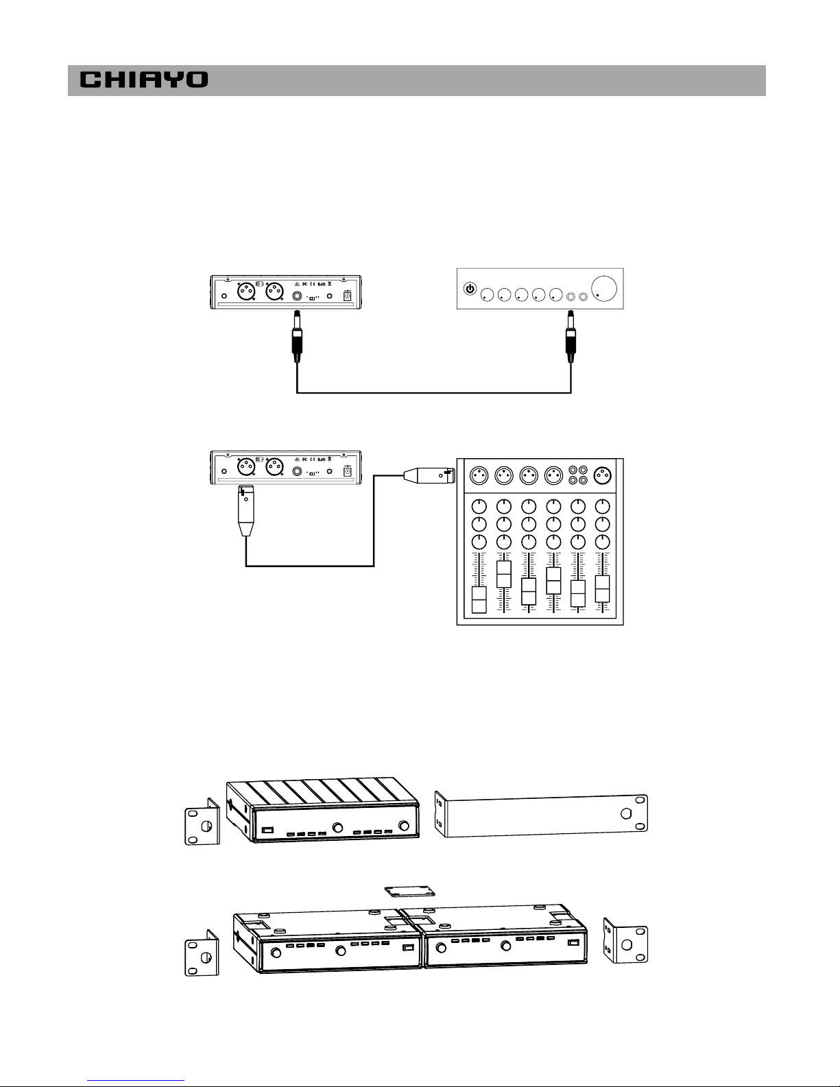
Audio output connection
There are two audio outputs on the back of the receiver, Mic-level balanced and Line-level
unbalanced. Use audio cable for the connection between the receiver and the amplifier/mixer.
Unbalanced audio connection: If the amplifier/mixer has a 6.3mm φphone jack, connect a
cable from the 6.3mm unbalanced audio output from the receiver to the amplifier/mixer.
Balanced audio connection: If the amplifier/mixer has an XLR input, connect a cable from
the balanced XLR audio output from the receiver to the amplifier/mixer input.
Unbalanced audio connection (6.3φ phone plug)
Balanced audio connection (XLR plug)
Rack mounting
The receiver can be cabinet-mounted by either one or two units. If only one receiver is to be
mounted, an optional kit is available and it's installed as shown in Fig 1. If two receivers are to
be mounted, they can be assembled by another kit and installed as shown in Fig 2.
Fig 1. Rack mount of one receiver
Fig 2. Rack mount of two receivers
AN T. B AN T. A DC IN
12 V
MI X E D OU TMI C OU T 1
1.G
2.
3.
MI C OU T 2 DI VE R S IT Y
1C H2C H
AN T. B AN T. A DC IN
12 V
MI X E D OU TMI C OU T 1
1.G
2.
3.
MI C OU T 2 DI V E R SI T Y
1C H2C H
ISO 9001|ISO 14001|OHSAS 18001
-6-
Parts and functions of handheld microphone DH-2400
1.Cartridge
2.Battery power LED
3.3-step power switch
(ON-MUTE-OFF)
4.LCD
5.Menu button
6.Setting button
7.Channel synchronizing button
8.Color cap
9.Battery compartment
10.Charging contacts
3-STEP power switch
Power status
ON
ON
MUTE
MUTE
OFF
Lock status
unlocked
locked
unlocked
locked
can’t be locked
To prevent other user from turning off the power, you may slide this switch to the right to lock
the microphone on stand-by or mute status. Slide to the left to unlock.
Battery installation & indicator
This microphone requires 2 x AA batteries to operate.
To install, remove the battery cover and slide the batteries into the battery compartment &
replace the battery cover.
Note: Batteries contain a corrosive acid that may leak and damage the microphone when
stored for a long period. Batteries should be removed from the microphone before storing
without use for more than 4 weeks.
When the microphone is switched ON, a blue LED②will blink once to denote the batteries
installed are in good condition. If the LED remains illuminated, it means the batteries are
weak and require replacement.
Channel synchronizing of the receiver and microphone
1. Unscrew the microphone’s lower housing
and then press and hold the synchronizing
button until LINK flashes on the LCD.
2. Press and press and hold the receiver’s
SYNC button until the frequency icon
appears. After successful channel
synchronizing, this icon will disappear
automatically.
►
►
FREQ
C H : 0 0 0
L I N K
SYNC
C H
FREQ CH.
RF AF
MHz
0 8 2
2482
-7-
Changing CHANNEL / FREQUENCY
1. Press-release MENU button until the
CHANNEL-FREQUENCY page appears.
2. Press and hold SET button until the channel
number flashes to denote readiness for
setting.
►
►
3. Press-release SET (UP) or MENU (DOWN)
button to select a new channel.
4. After a channel is chosen, wait about 3
seconds to store the setting.
►
Battery type setting
1. Press-release MENU button until the
CHANNEL-BATTERY TYPE page appears.
2. Press and hold SET button until NIMH or
AKLN flashes to denote readiness for setting.
►
►
3. Press-release SET or MENU button to
select either NiMH (rechargeable battery) or
AKLN (alkaline battery).
4. After a battery type is chosen, wait about 3
seconds to store the setting.
►
Important: NiMH battery must be selected when rechargeable battery is being used. Never
select AKLN (alkaline) when microphone is intended for charging as alkaline battery isn’t
rechargeable. Wrong battery selection will result in battery sensing electronics to display wrong
and misleading status information.
MHz
C H : 0 8 2
2482
MHz
C H : 0 8 2
2482
MHz
C H : 0 7 2
2472
MHz
C H : 0 7 2
2472
C H : 0 8 2
A K L N
C H : 0 8 2
A K L N
C H : 0 8 2
N I M H
C H : 0 8 2
N I M H
ISO 9001|ISO 14001|OHSAS 18001
-8-
RF power setting
1. Press-release MENU button until the
CHANNEL-RF POWER page appears.
2. Press and hold SET button until the RF
power figure flashes to denote readiness for
setting.
►
►
3. Press-release SET (UP) or MENU (DOWN)
button to choose an output level from 0db to
20db
4. After an output level is chosen, wait about 3
seconds to store the setting.
►
Important: Lower output power will reduce the RF transmission distance and higher output
power will extend the possible RF transmission distance. However, higher output power places
slightly more load on the battery and will reduce operating duration faster than lower output
power.
Parts and functions of belt-pack transmitter DB-2400
1. Antenna
2. LCD
3. Cover release button
4. Channel synchronizing button
5. Menu button
6. Setting button
7. High-impedance gain control (GT)
8. Low-impedance gain control (MT)
9. Battery compartment
10.Power switch
11.Battery power LED
12.Audio input connector
13.Charging contacts
Battery installation & indicator
This belt-pack requires 2 x AA batteries to operate.
To install, open the battery cover using the cover release buttons and insert the batteries into
the battery compartment.
Note: Batteries contain a corrosive acid that may leak and damage the belt-pack when stored
for a long period. Batteries should be removed from the belt-pack before storing without use for
more than 4 weeks.
C H : 0 8 2
R F 0 8
C H : 0 8 2
R F 0 8
C H : 0 8 2
R F 1 2
C H : 0 8 2
R F 1 2
1
2
3 3
8
6
7 4
5
9
10 11
12
13
-9-
When the transmitter is switched ON, the battery power LED○
11 will blink once to denote the
batteries installed are in good condition. If the LED remains illuminated the batteries have
expired and require replacement.
GAIN setting (GT|MT)
Gain control enables the user to set different output levels.
GT⑦is for the use of instrument with high impedance, such as guitar.
MT⑧is for the use of low impedance such as lapel or headset microphones.
Channel synchronizing of the receiver and transmitter
1. Open the cover and then press and hold the
synchronizing button until LINK flashes on
the LCD.
2. Press and hold the receiver’s SYNC button
until the frequency icon appears. After
successful channel synchronizing, this icon
will disappear automatically.
►
►
Changing CHANNEL / FREQUENCY
1. Press-release MENU button until the
CHANNEL-FREQUENCY page appears.
2. Press and hold SET button until the channel
number flashes to denote readiness for
setting.
►
►
3. Press-release SET (UP) or MENU (DOWN)
button to select a new channel.
4. After a channel is chosen, wait about 3
seconds to store the setting.
►
FREQ
C H : 0 0 0
L I N K
SYNC
C H
FREQ CH.
RF AF
MHz
0 8 2
2482
MHz
C H : 0 8 2
2482
MHz
C H : 0 8 2
2482
MHz
C H : 0 7 2
2472
MHz
C H : 0 7 2
2472
ISO 9001|ISO 14001|OHSAS 18001
-10-
Battery type setting
1. Press-release MENU button until the
CHANNEL-BATTERY TYPE page appears.
2. Press and hold SET button until NIMH or AKLN
flashes to denote readiness for setting.
►
►
3. Press-release SET or MENU button to
select either NiMH (rechargeable battery) or
AKLN (alkaline battery).
4. After a battery type is chosen, wait about 3
seconds to store the setting.
►
Important: NiMH battery must be selected when rechargeable battery is being used. Never
select AKLN (alkaline) when transmitter is intended for charging as alkaline battery isn’t
rechargeable. Wrong battery selection will result in battery sensing electronics to display wrong
and misleading status information.
RF power setting
1. Press-release MENU button until the
CHANNEL-RF POWER page appears.
2. Press and hold SET button until the RF
power figure flashes to denote readiness for
setting.
►
►
3. Press-release SET (UP) or MENU (DOWN)
button to choose an output level from 0db to
20db
4. After an output level is chosen, wait about 3
seconds to store the setting.
►
Important: Lower output power will reduce the RF transmission distance and higher output
power will extend the possible RF transmission distance. However, higher output power places
slightly more load on the battery and will reduce operating duration faster than lower output
power.
C H : 0 8 2
A K L N
C H : 0 8 2
A K L N
C H : 0 8 2
N I M H
C H : 0 8 2
N I M H
C H : 0 8 2
R F 0 8
C H : 0 8 2
R F 0 8
C H : 0 8 2
R F 1 2
C H : 0 8 2
R F 1 2
CHIAYO ELECTRONICS CO.,LTD.
Http://www.chiayo.com.tw|Email: sales@chiayo.com.tw
Office: 30, Lane 27, Section 4, Jen-Ai Road, Taipei 10685, Taiwan|Tel: 886-2-27415741|Fax: 886-2-27525242
Factory: 88, Chung-Hsiao Street 2, Chiayi 60080, Taiwan|Tel: 886-5-2711000|Fax: 886-5-5767611
12I1367

Other manuals for DWR-2420

1

This manual suits for next models

1

Other Chiayo Microphone manuals

Chiayo SQ-6100 IrDA User manual

Chiayo

Chiayo SQ-6100 IrDA User manual

Chiayo NH-3100 User manual

Chiayo

Chiayo NH-3100 User manual

Chiayo GMW-200 User manual

Chiayo

Chiayo GMW-200 User manual

Chiayo DH2400 User manual

Chiayo

Chiayo DH2400 User manual

Chiayo IrDA-9000 User manual

Chiayo

Chiayo IrDA-9000 User manual

Chiayo SQ-9000 IrDA User manual

Chiayo

Chiayo SQ-9000 IrDA User manual

Chiayo GM-243 User manual

Chiayo

Chiayo GM-243 User manual

Chiayo R-303 User manual

Chiayo

Chiayo R-303 User manual

Chiayo SDR-5900 User manual

Chiayo

Chiayo SDR-5900 User manual

Chiayo SQ-5100 IrDA User manual

Chiayo

Chiayo SQ-5100 IrDA User manual

Chiayo SQ-1016 User manual

Chiayo

Chiayo SQ-1016 User manual

Chiayo ITX2 User manual

Chiayo

Chiayo ITX2 User manual

Chiayo SQ-6100 IrDA User manual

Chiayo

Chiayo SQ-6100 IrDA User manual

Chiayo GMW-216 User manual

Chiayo

Chiayo GMW-216 User manual

Chiayo GM-200 User manual

Chiayo

Chiayo GM-200 User manual

Chiayo SDR-1932 User manual

Chiayo

Chiayo SDR-1932 User manual

Chiayo SQ-5016 User manual

Chiayo

Chiayo SQ-5016 User manual

Chiayo IWM-402 User manual

Chiayo

Chiayo IWM-402 User manual

Popular Microphone manuals by other brands

Studiomaster KR-12 instruction manual

Studiomaster

Studiomaster KR-12 instruction manual

Instarter 23267 instruction manual

Instarter

Instarter 23267 instruction manual

Beyerdynamic MCE 58 Product information

Beyerdynamic

Beyerdynamic MCE 58 Product information

MicW Audio iShotgun Manual for use and maintenance

MicW Audio

MicW Audio iShotgun Manual for use and maintenance

KEEPDRUM WS03 manual

KEEPDRUM

KEEPDRUM WS03 manual

Technaxx MusicMan PRO BT-X35 user manual

Technaxx

Technaxx MusicMan PRO BT-X35 user manual

Sennheiser ME 34 instruction manual

Sennheiser

Sennheiser ME 34 instruction manual

Monacor IMG STAGELINE ECM-306B/SW operating instructions

Monacor

Monacor IMG STAGELINE ECM-306B/SW operating instructions

Bosch MW1-RX Installation and user instructions

Bosch

Bosch MW1-RX Installation and user instructions

Boya BY-WM3D instruction manual

Boya

Boya BY-WM3D instruction manual

Kenwood MC-80 instruction manual

Kenwood

Kenwood MC-80 instruction manual

Uniden BM100 owner's manual

Uniden

Uniden BM100 owner's manual

WSTER WS-858 user manual

WSTER

WSTER WS-858 user manual

Gioteck TX-1 user manual

Gioteck

Gioteck TX-1 user manual

Wireless Pacific X10DR ELITE User's card

Wireless Pacific

Wireless Pacific X10DR ELITE User's card

Shure Centraverse Series Installation

Shure

Shure Centraverse Series Installation

Sennheiser MD 511 Instructions for use

Sennheiser

Sennheiser MD 511 Instructions for use

Palmer RIVER Series user manual

Palmer

Palmer RIVER Series user manual

manuals.online logo
manuals.online logoBrands
  • About & Mission
  • Contact us
  • Privacy Policy
  • Terms and Conditions

Copyright 2025 Manuals.Online. All Rights Reserved.