Crown SMX-6 Operating instructions

Troubleshooting — 1
Notes
Rev 3-97 * School
IQ System Troubleshooting
OVERVIEW
The purpose of this chapter is to provide detailed information about system
level troubleshooting of IQ Systems. Most problems with IQ occur at the time
of installation. Good installation techniques take care of most problems before
they happen. This chapter provides some installation tips, but it assumes little
about the quality of installation techniques. It is also important to remember that
how well a system sounds or operates depends heavily on good system design
and installation. The best troubleshooting skills may do very little for a poorly
designed audio system. This chapter deals with troubleshooting IQ compo-
nents from a control standpoint, not audio performance.
OBJECTIVES
At the completion of the lecture and labs for this chapter the student should be
able to meet the following list of objectives:
• List the steps of universal troubleshooting techniques.
• Describe each step of universal troubleshooting techniques.
• State the most common installation problems encountered with IQ.
• List the configuration parameters that must match between software and
interface hardware.
• State the maximum operating length RS232 and RS422.
• State the maximum loop capacitance for normal Crown Bus operation.
• State the valid range of loop addresses.
• Explain what a valid component identification is.
• List the software functions that can be used to troubleshoot IQ.
• Explain how Roll Call is a troubleshooting tool.
• Describe the proper method of taking a voltage measurement to check
Crown Bus wiring.
• State the expected voltages for normal, open, shorted, and reverse polarity
Crown Bus wiring.
• Describe the proper method of taking current measurements to check
Crown Bus signal waveforms.
• State the minimum current for a current high and the maximum current for
a current low.
• Explain how software break detection works.
• List the most likely reasons why you might see an Interface Not Found
message.
• List the most likely reasons why you might not find components on a loop.
• Explain what happens to loop communication when an IQ component loses
power.
• State what resources are available to help you troubleshoot an IQ problem.
SLIDES
1. Universal Techniques
• Symptom Recognition
• Symptom Elaboration
• Probable Faulty Block
• Probable Faulty Function
• Repair
• Retest

2 — Troubleshooting
Notes
Rev 3-97
@ Crown
2. Common IQ Problems
• Swith configuration
• RS232/422 cables
• Non-standard serial ports
• PC does not meet requirements
• Software configurations
• Design error or campatability problem
• Crown Bus wiring errors
• Crown Bus capacitance
3. Troubleshooting Tools
• Roll Call (File|New)
• Engage/Upload
• Break Detect
• Voltage Measurements
• Current Waveform Measurements
• Documentation
• Technical Support (1-800-342-6939/219-294-8200)
4. Voltage Measurement: OK
Figure 1
5. Voltage Measurement: Shorted
Figure 2
6. Voltage Measurement: Open
Figure 3
7. Voltage Measurement: Reverse Polarity
Figure 4
8. Current Measurement
Figure 5
9. Does The Software Run?
• PC Requirements
• Environment (Windows, DOS...)
• Corrupt or Incorrect Files
10. Is It Possible to Run a Roll Call?
• Demo Version
• Serial Port Parameters
11. No Interface Found?
• Interface off/unplugged
• RS232/422
• Serial port setup in software
• Interface setup
• Windows Control panel setup
• SMX in CLN mode
• RS232 smart switcher
12. Are All Components Found?
• Software support
• OIF/DLL files
• Interface compatability
• Power
• Loop wiring
• Capacitance
• Duplicate or invalid addresses
13. Factory Support Issues
• Hardware serviced only at Crown
• Upgrades
• Licensing of software
• Development products

Troubleshooting — 3
Notes
Rev 3-97 * School
UNIVERSAL TROUBLESHOOTING TECHNIQUES
There are some basic procedures which apply to troubleshooting at any level,
whether it be component level circuit board repair or very general system level
service.
Symptom Recognition
The first step in troubleshooting is to determine that a problem really exists. All
too often a problem exists in a system that is never identified and never fixed.
The long term result is an unsatisfied customer. On the other hand, a system
operator may expect a certain result and feels that there is something wrong
with the system when he does not get that result. Recognizing symptoms of an
actual problem may be very obvious or may be quite subtle. In either case a
solid understanding of how an IQ System operates is critical to determining if
a problem is real. Symptom recognition, then, is the determination that a
problem exists by virtue of the system response being different from the
expected response.
Example: Amplifiers in equipment room #1 do not respond to commands sent
from the computer.
Symptom Elaboration
Once you decide that a problem exists you need to try to find out as much about
the problem as possible by examining the nature of the symptoms. This step
in the process often involves some very basic testing to get you looking in the
right general area for the exact problem. Specifically is the process of defining
the exact nature of the problem.
Example: When taking a Roll Call all components appear except those in
equipment room #1.
Probable Faulty Block
Once you have gathered all the information you can about the specific nature
of the problem you can usually determine where to start looking. This step often
involves checking your symptoms against system documentation.
Example: Examine system prints and find that component in equipment room
#1 are all on Crown Bus loop 3 and they are the only components on loop 3.
Problem is likely to be a communication problem somewhere in loop 3.
Probable Faulty Function
At this point it is often necessary to use your troubleshooting tools to break the
problem down until you find out exactly what the problem is.
Example: Visually inspect cable connections for loop 3 at the interface and in
the equipment room. You locate a Crown Bus cable that has been pulled loose
from a PIP data input at Amplifier 13. An alternate method of testing if the DOS
software is used is to run a SEARCH on loop 3 using the IQ software. It would
reveal a “Break on loop 3 before Amplifier 13.” This would tell you where to go
to physically look for a cable problem.
Problem Verification & Repair
The final step once the problem is found is to fix it and test the system. There
have been times in every technician’s life where they think they have found the
problem, performed a repair, and found that something else was wrong. It is

4 — Troubleshooting
Notes
Rev 3-97
@ Crown
very important to verify that the system is, in fact, working after you perform a
repair.
Example: Plug the cable back into the PIP then run a Roll Call to verify that all
system components are on line then verify that the amplifiers respond to
commands sent from the computer.
COMMON IQ SYSTEM PROBLEMS
Most IQ System problems occur at the time of installation. Most of those are
related to hardware or software communication setup. Other than hardware or
software settings, loop capacitance is a significant factor. In many cases wire
selection is becomes a critical factor. In longer loops where capacitance is
questionable it may be necessary to add an IQ-RPT Repeater to the loop.
Hardware Setup
Switches are a necessary evil in the setup of any IQ System. Component
addresses must be a valid value with no duplicates of same type of component
on the same Crown Bus loop. Baud, parity, and any other hardware switch
settings on the component serving as system interface must be properly
configured. Parity should, except in very unusual circumstances, be off. The
computer, software, and RS232/422 cable must be capable of supporting the
baud selected at the interface. AC power must be available and the interface
must be on. RS232/422 cable must be connected at both ends to the proper
computer serial port as well as the proper IQ System component. You must
have a 16550 UART for the computer com port. The computer itself must meet
the minimum requirements for the type of software being used.
IQ components are not likely to fail, but it is not impossible. Lightening is a
respecter of no one. The most common type of hardware failure is opto-isolator
damage due to high voltage spikes from lightning or other power sources. The
only other major source of hardware failure is failure to follow proper static
handling procedures of components with exposed static sensitive electronics
such as PIP module and card cage components.
Software Setup
Most software parameters that affect whether or not you can communicate
properly with the system in DOS software are found on the F10 control panel
screen. In IQ For Windows both the program communication settings and the
Windows Control Panel effect communication. At a minimum those settings
include com port enable, com port number, IRQ number, Base Address, and
baud.
Crown Bus Loop
The Crown Bus is a communication standard based on the transmission of
proprietary IQ command protocol on a serial data loop. Although other media
may be used to transmit the protocol, IQ hardware uses 20 ma current as the
media to go into and out of components. Digital signals are, by their nature,
simply pulses of DC. This in turns means that data signals are polarity sensitive.
One of the most common mistakes made when wiring Crown Bus connections
is to reverse the polarity of a Crown Bus cable. A broken or unplugged cable
or polarity reversal anywhere in the loop consitutes a break in the loop. When
the IQ-INT II unit is used as the interface a common problem is to have the input
and output lines for one loop connected to the interface output of one loop and
the input of another loop at the interface.

Troubleshooting — 5
Notes
Rev 3-97 * School
Cable capacitance is another issue. In general Crown recommends that you
keep maximum loop capacitance at 30 nF or less, although in most cases a loop
will operate properly at up to 40 nF. To calculate loop capacitance add up the
total loop wire length, multiply that by the capacitance per foot (or meter) rating
of the cable used, and add 60 pF per component on the loop. Restart the
calculation at the output of each Repeater in the loop. RFI is rarely a problem
with twisted pair Crown Bus cable because the Crown Bus is usually a 20 ma
current loop. Induced noise may, however, be a consideration.
PROBLEM PREVENTION (INSTALLATION TECHNIQUES)
Good installation techniques will save you a great deal of trouble after the
installation is thought to be complete. The best way to install a large IQ System
is to test the system a rack at a time, then add racks to the loop(s) one at a time.
This may seem more time consuming, but in a large system you may save hours
of work later by running a ten minute check in the equipment room.
Always use proper static handling procedures. Never pull a PIP module out or
put one into an amplifier if the amplifier is powered up. It is best to always unplug
the amplifier and wait a few seconds before taking a PIP card in or out. If you
are involved in a situation where firmware is being upgraded always ensure that
a trained technician performs the actual chip replacement.
When you setup a component one of the parameters you always have to deal
with is the component address. To save time later it is always recommended
that you mark components with their loop address and annotate system
drawings to accurately reflect those addresses.
TOOLS AVAILABLE
There are many resources available to troubleshoot an IQ System problem. The
software has a number of powerful features, the hardware also has valuable
tools built in. A good visual inspection finds many problems before you have
to use any equipment or software. Basic test equipment such a voltage meter
can tell you a great deal, and if all else fails you can always resort to checking
documentation.
Roll Call
Roll Call is the first and most important tool you have in the software. When you
run a Roll Call the software establishes communication, first with the interface,
then each component on each loop of the interface. The Roll Call reports status
step by step. It gives you status of communication with the interface, running
status of components it finds, and inventory totals. Note that all the inventory
information in the world is of little value unless you know what you are supposed
to find. It is critical that you know what the inventory should be. You should be
able to run a Roll Call and find all the components that are connected into the
system, and you should be able to get that inventory consistantly.
When you perform a Roll Call the software establishes RS232 communication
with the interface first. The interface is interrogated and must report its identity
as a component type. This process must be completed before any further steps
may be taken. Even if the software you are using does not support the
component serving as system interface, the software should recognize that an
unidentified component is the interface.

6 — Troubleshooting
Notes
Rev 3-97
@ Crown
ONLINE Indicator
After running a Roll Call and finding components you need to be able to
maintain communication with the system. Each component has an ONLINE
indicator available in the software. This indicator is a software tool that lets you
know you are in contact with the desired unit. If the ONLINE indicator goes off
you should be able to reestablish contact by running a Roll Call, using
Control+E, loading a dataframe file, or by using On Line Search.
Engage (^E)
If you have either had and lost communication or you have loaded a dataframe
without successfully communicating you may engage the dataframe by using
Control+E. This key combination engages the dataframe and forces all the
settings in the software out through the com port of the computer. The settings
for each component that are in the inventory of the dataframe file will be forced
to the system. If the system is there and all loops and communication pathways
are intact all settings should be engaged and all components should come on
line. Part of the process of engaging the dataframe is to check each component
in the inventory and ensure that they are present and on line.
On Line Search (DOS Software Only)
The On Line Search feature, found on the F10 control panel screen, performs
a function which is similar to Roll Call. When you run a Roll Call the system takes
an inventory, uploads component settings, and fills in control blocks with data.
When you use On Line Search the software compares the inventory against the
actual system. This is done automatically at regular intervals. It serves to
automatically refresh On Line indicators. If a component drops off line for some
reason, such as power loss, the On Line Search feature will automatically
reestablish communication with that component when power is restored. It will
also restore communication to a whole loop of components if the loop becomes
broken and is later restored. While the software contains more components in
its inventory than are actually on line this feature will cause the software to
temporarily pause while the on line search is in progress.
On Line Search is the feature you want to use to build a dataframe file manually.
When a component is added to a dataframe manually the on line search feature
not only finds the component and brings it on line, but it also uploads the
settings from the component into the software and makes any changes
necessary to settings in the dataframe. On Line Search will upload settings
even if you are only reestablishing communication. On Line Search is a feature
that may be turned on and left on at all times in many systems, but it is important
to understand the effects of this feature so that the software does not surprise
you. Note that On Line Search does not actually locate or identify breaks; it
continuously verifies the dataframe inventory.
Break Detect
BreakDetectisafeaturethatcanbeswitchedonattheF10controlpanelscreen
of DOS software; it is always on in IQ For Windows. It allows the software to
automatically listen for signals from components that identify breaks. Before
you can understand what this feature really does it is important to understand
what happens in the system when a break occurs in the Crown Bus loop.
AllIQ components sense Crown Busdata input continuity. A logiclow is actually
a high current condition and a logic high is a low current condition. When a
component goes for a period of time without seeing a high current (more than
12 milliamperes) input the unit recognizes the condition as a break in commu-

Troubleshooting — 7
Notes
Rev 3-97 * School
nication. Because data flows one direction around the loop the component will
assume that it can still send a message out to downstream components and
back to the interface. The component begins to continuously dump its
identification. If there is continuity back to the interface data input the interface
will carry the data stream of that component’s identification through the RS232
line and back to the computer. When the Break Detect feature of the software
is enabled it will listen for such a stream and report it to the operator. Because
the information reported includes the loop address and type of component you
can tell that the break in the Crown Bus is in the line coming into the specified
component.
Break Detect works with breaks that result in loss of current continuity in the
Crown Bus cables. Remember that a break may be an open cable (positive or
negative side) or a polarity reversal of the cable. Note that a hardware failure
of the input isolator device or output current driver also constitutes a break.
Break Detect will not find a capacitance problem, nor will it find an RFI problem.
More specialized utility programs may be required to run specialized tests for
problems like that.
Break Detect is a feature you want on in most cases. It reports a break at the
time it occurs.
Search (DOS Software Only)
Another feature found on the F10 control panel screen that is used to diagnose
system communication problems is simply called Search. Search is a manual
break detection process that you can run at any time. It checks a specified loop
for continuity in the same manner as Break Detect. It is a feature you would use
if you were not able to establish loop communication initially, you missed the
alert on the screen, or you want to verify the break. To use Search you need to
select the loop to search then toggle the Search feature on. It goes off
automatically when it is done performing its check.
When you perform a Search you usually get one of three messages. If the loop
is intact and there are no problems it gives you a message that says the loop
is okay. If there is a break at the input of an IQ component with an address the
software will tell you the location of the break. If the break occurs at the input
to the interface or the input to a non-addressable item, such as a Repeater or
fiber optic receiver, a message will appear that says it cannot locate the break,
the break may be before the first component.
All Amps
A special set of features exist in the software that can prove particularly useful
in large amplifier systems. As much as Crown might like to sell systems with
large numbers of automatic mixers, relay cards, or other devices, most IQ
Systems with a relatively large number of components are primarily amplifier
systems. For this reason special All Amps features are in the software to turn
all amplifiers in the entire system on or off, mute or unmute, or all Data LED on
or off. The All Amps features actuate all amplifiers on any loop regardless of
address and regardless of whether they are in the dataframe inventory.
As a diagnostic tool the All Amps Data LED controls may be very helpful in
amplifier systems to locate a break if other software features such as Break
Detect or Search fail to locate the communication problem. When Data LED is
turned on for all amplifiers using the All Amps control, all amplifiers that receive
the message turn on their Data LED indicator. After forcing on Data LED

8 — Troubleshooting
Notes
Rev 3-97
@ Crown
indicators you perform a visual inspection of your amplifier racks until you find
the point where one amplifier has its Data LED on and the next one in the loop
is not lit. When you find this point you have located the break.
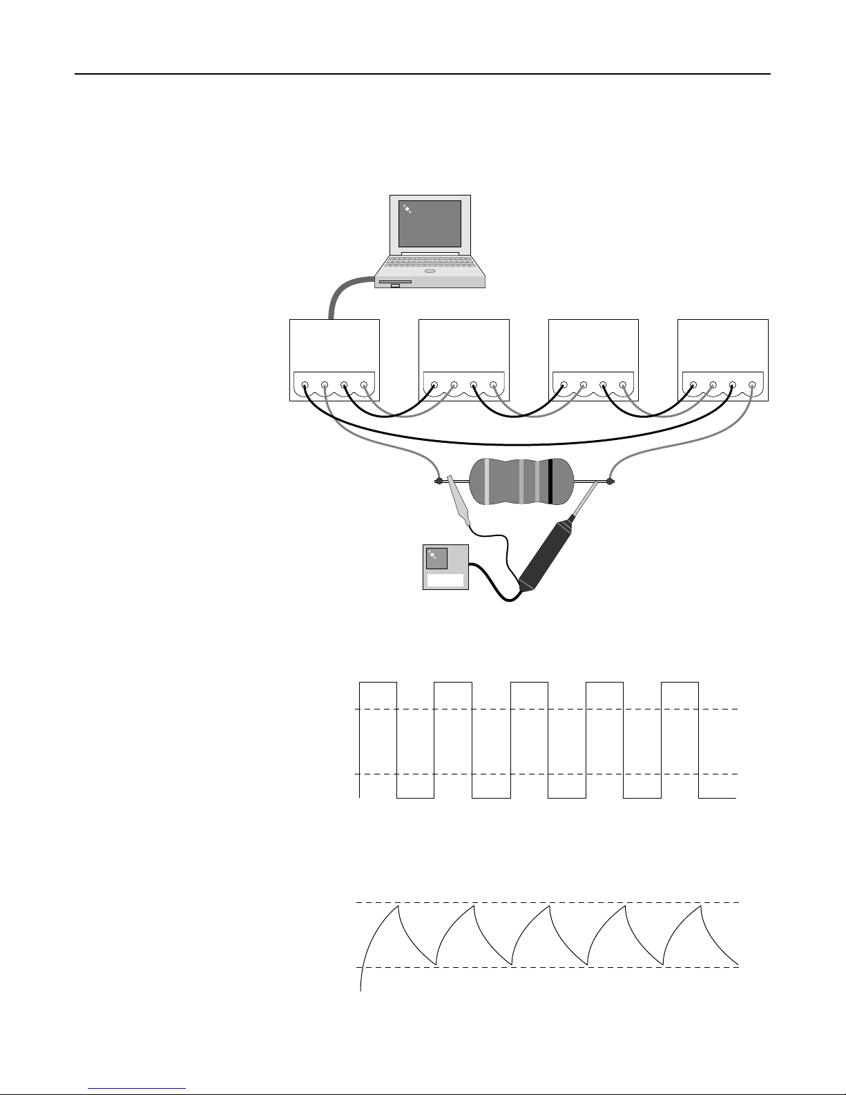
Expected Crown Bus Voltages
Another way of checking for a Crown Bus wiring problem is to use a DC voltage
meter and check the voltage across the positive and negative lines of the Crown
Bus cable. Figures 1 through 4 demon-
strate the various voltages you might see
under various loop wiring conditions.
If the cable is connected properly, as
shown in Figure 1, between two compo-
nents with good continuity,
proper polarity, and both of the
componentsarepoweredupand
operating you should expect to
see approximately 2.5 VDC
across the positive and negative
Crown Bus wires.
If polarity of the Crown Bus is
reversed you will see a voltage
drop corresponding to the drop
across a diode, or about 0.7
VDC. Figure 2 shows measure-
ments being taken at the point in
the loop where the cable is re-
versed.
If you have no voltage drop at all
the problem may be an open in
one of the wires between the
output of the upstream device
and the point of measurement
as shown in Figure 3. It could
alsobeashortbetween the posi-
tive and negative wires or a
shortedopto-isolatoratthedown-
stream input device, as shown in
Figure 4. Another possibility
would be the upstream device
may not be powered up. If cable
continuity is proven good and
the component is turned on and
plugged in the problem may be
a failure of the current driver
circuitry.
A high voltage condition (10 to
15 VDC) occurs when there is an
open between the point of mea-
surement and the downstream
input device, as shown in Figure
3. The open may be in the Crown
OUT IN
+–+–
SMX 1
OUT IN
+–+–
SMX 2
OUT IN
+–+–
SMX 3
OUT IN
+–+–
SMX 4
0.7 VDC
+
–
Loop polarity is reversed between SMX 2
and SMX 3. Break Detect reports "Break
Before SMX 2" because SMX 2 senses loss
of input continuity and sends break report
with component ID. Meter reads diode
voltage drop due to input optic isolator.
0.7 VDC
+
–
OUT IN
+–+–
SMX 1
OUT IN
+–+–
SMX 2
OUT IN
+–+–
SMX 3
OUT IN
+–+–
SMX 4
2.5 VDC
+
–
Loop is OK. Expected voltage is
approximately 2.5 VDC at each
input and output.
Figure 1. Loop Voltage Check
Figure 2. Loop Voltage Check With Cable Polarity Reversed

Troubleshooting — 9
Notes
Rev 3-97 * School
Bus cable or connectors, or it may mean an open opto-isolator at the input
device.
Crown Bus Wave Form Testing
When a loop problem exists and you have determined that the DC character-
istics of the Crown Bus are all good and that there are no breaks, it is time to
get serious and look at the data signal wave form. This check will tell you if there
is a capacitance or RFI problem on a loop.
General symptoms of a capacitance or RFI
problem on a loop would be partial or
inconsistant loop operation. In some cases it
may not be possible to establish communi-
cationatall,andinothercasesghost
components may appear at
a Roll Call that are not in the
system at all.
To perform this test you will
need to modify a loop cable
by adding a 100 ohm resis-
tor in series with the nega-
tive wire of the cable. You
will also need an oscillo-
scope to view the signal.
Signals may be generated
on the Crown Bus by run-
ning Roll Calls, loading
dataframes, or by discon-
necting a Crown Bus cable
at the input to a component
at the beginning of the loop.
Figure 5 shows a test rig
setup for wave form mea-
surement. Note that if an
ungrounded scope is used
it makes no difference
whether the resistor is in the
positive or negative leg, but
if a grounded scope is used
you must put the resistor in
the negative leg and the
negative lead of the scope
on the side of the resistor
electrically closest to the
output device.
Figure 6 shows what a good
data signal looks like. Note
that greater than 12 ma is
required for a current high
(data logic low) and current
level must drop below 4 ma
for a current low (data logic
high).
OUT IN
+–+–
SMX 1
OUT IN
+–+–
SMX 2
OUT IN
+–+–
SMX 3
OUT IN
+–+–
SMX 4
15 VDC
+
–
Loop is broken between SMX 2 and SMX 3.
Break Detect reports "Break Before SMX 2"
because SMX 2 senses loss of input continuity
and sends break report with component ID.
High voltage at the output driving open,
no voltage at input.
0 VDC
+
–
OUT IN
+–+–
SMX 1
OUT IN
+–+–
SMX 2
OUT IN
+–+–
SMX 3
OUT IN
+–+–
SMX 4
0 VDC
+
–
Loop is shorted between SMX 2 and SMX 3.
Break Detect reports "Break Before SMX 2"
because SMX 2 senses loss of input continuity
and sends break report with component ID.
No voltage is read at either connector due
to short. SMX 3 is protected by current limit.
0 VDC
+
–
Figure 3. Loop Voltage Check With Loop Open
Figure 4. Loop Voltage Check With Loop Shorted

10 — Troubleshooting
Notes
Rev 3-97
@ Crown
Figure 7 shows what a wave form may look like when the loop capacitance is
too high. Note that the waves are rounded and unable to reach magnitudes
required for reliable communication. In high capacitance situations the prob-
lem may result in loss of high current or low current values. When the problem
isextremely high RFI the problemismore likely to be alossof low current values.
OUT IN
+–+–
SMX 1
OUT IN
+–+–
SMX 2
OUT IN
+–+–
SMX 3
OUT IN
+–+–
SMX 4
100 Ω
+–
SCOPE
4 ma
Low
Current
12 ma
High
Current
Ideal Crown Bus Waveform Shape
High Capacitance Crown Bus Waveform Shape
4 ma
Low
Current
12 ma
High
Current
Figure 5. Loop Current Test
Figure 6. Ideal Loop Signal
Figure 7. Loop Signal With High Capacitance

Troubleshooting — 11
Notes
Rev 3-97 * School
Documentation
Crown provides instruction manuals for every hardware and software product
that is in regular production. These are resources that usually provide the
answers. The most complete and accurate information possible is compiled in
these documents to assist you with installation and operation. These docu-
ments are usually product specific and in many cases do not cover complex
system level situations that you have to deal with. We also update our
documentation from time to time and continually strive to provide the best
information possible. If you keep old manuals for reference keep in mind that
new documentation may correct errors or provide additional information that
older manuals may not have. There may be other considerations as well such
as product changes.
Crown Technical Support Group: 1-800-342-6939/1-219-294-8200
A team of people at the Crown factory exists for the purpose of providing
technical assistance with Crown products. If you need help the Technical
Support Group is available. Normal business hours (8 am to 5 pm EST) are kept,
but if you are working on a major project and feel that after hours assistance may
be needed you may contact us to make special arrangements. If you are calling
about a problem you are having with the system it is much easier to help you
if you have taken the time to check available documentation. It is also very
helpful if you have serial numbers, software revision numbers, or other relavent
information handy when you call. If a hardware product is defective we will
assist you in getting the product repaired. Refer also to the Factory Service
section later in this chapter. If a software product is defective you should call
us to make arrangements to take care of the problem. With software there are
often special procedures that are beyond the scope of conventional hardware
service procedures.
STEP BY STEP IQ SYSTEM TROUBLESHOOTING
There are a few basic questions that must all be answered yes to prove that an
IQ System is operating properly. Does the software perform a Roll Call? Does
the software find and identify an interface at Roll Call? Does the software find
all components in the system at a Roll Call? Do all components remain in
communication with the computer after Roll Call? If the answer to each of these
questions is yes, then any problems you are having are probably in the audio
path or in the way that components are programmed. To learn how to set up
a component to get a desired result refer to the applicable chapter of the text
book or the software and hardware manuals associated with that component.
Figure 8 is a troubleshooting flow chart. It is impossible to cover every possible
problem, however most of the more significant possibilities are explored. The
following sections walk through the block diagram in greater detail.

12 — Troubleshooting
Notes
Rev 3-97
@ Crown
Question 1: Does the software program run?
Yes: Proceed to question 2.
No: Proceed to question 1A.
Question 1A: Does the PC meet the minimum specifications?
Yes: Proceed to question 1B.
No: Get another computer.
Question 1B: Is the correct operating system being used?
Yes: Proceed to question 1C.
No: The DOS software packages usually operate properly on machines running
Windows 95, however this is not always true. It may be necessary to boot
directly to DOS. If in doubt, use a PC that meets the minimum requirements with
the specified operating system.
Question 1C: Are any files corrupted?
Yes: Re-install the program.
No: If the problem cannot be resolved contact Crown.
Figure 8. Troubleshooting Flow Chart
Does the
software run?
PC
Requirements
Operating
System
Corrupt
Files
Will it run
a Roll Call?
Demo
Software
Serial port
configuration
Do you find
the interface?
Off or
Unplugged
Correct Cable
Connected
Correct Port
Connected
Port
Active
Port
Setup
Interface
Setup
SMX in
CLN Mode
Do you find
all units?
Is the Whole
Loop Missing?
Loop
Wiring
Loop
Capacitance
System
Power
Fiber
Optics
Does everthing
stay on-line?
Valid
Addresses
OIF/DLL
Support
Component
Power
Mixer
Interface
Loop
Capacitance
EVERYTHING
IS OKAY
16550
UART
Loop
Capacitance
Mixer
Interface
PSI
Battery
Smart RS232
Switcher
N
Y Y Y Y Y
N N N N
Y
N
If none of these
are the problem
N

Troubleshooting — 13
Notes
Rev 3-97 * School
Question 2: Does the software perform a Roll Call?
Yes: Proceed to question 3.
No: Proceed to question 2A.
Question 2A: Is the software program a demonstration version only?
Yes: The program will not communicate with an actual system if it is a
demonstration only version.
No: Proceed to question 2B.
Question 2B: Is the serial port properly configured?
Yes: Check the computer’s BIOS settings. If the problem cannot be resolved
Contact Crown.
No: Check the Windows Control Panel for serial port configuration. Check the
software serial port configuration and ensure the proper port is selected that
you are not working offline. Check the computer’s BIOS.
Question 3: Does the software find the interface at Roll Call?
Yes: Proceed to question 4.
No: Proceed to question 3A.
Question 3A: Is the interface off or unplugged from the AC power source?
Yes: Restore power.
No: Proceed to question 3B.
Question 3B: Is the correct RS232/422 cable being used?
Yes: If a Drone is the system interface it is sometimes necessary to remove Pin
4 from the male connector on the standard RS232 cable. Proceed to question
3C.
No: Use the correct cable.
Question 3C: Is the RS232 cable connected correctly at both ends?
Yes: Proceed to question 3D.
No: Connect the cable properly. Make sure you are connected to the proper
port on the computer.
Question 3D: Is the com port active in software (you do not have Working Offline
checked)?
Yes: Proceed to question 3E.
No: Set the port to active or working offline unchecked.
Question 3E: Is the serial port configured properly in the IQ software, Windows
Control Panel, and the computer BIOS?
Yes: Proceed to question 3F.
No: Configure the computer.
Question 3F: Is the interface properly configured?
Yes: Proceed to question 3G.
No: Set baud to 9,600, 19,200, or 38,400. Note that maximum speed may be
limited by long RS232 runs. Ensure that the RS232/422 switch is set correctly.
Set parity to off, data bits to 8, stop bits to 1.
Question 3G: If an SMX-6 is used as interface, is it in CLN mode?
Yes: Use another component such as an INT II or PSI as the system interface
or, if no other interface is available, reset the SMX by powering it down and
temporarily disconnecting the battery.

14 — Troubleshooting
Notes
Rev 3-97
@ Crown
No: Proceed to question 3H.
Question 3H: Is an IQ-PSI the interface?
Yes: Replace the battery or use an AC adapter.
No: Proceed to question 3I.
Question 3I: Is an RS232 Switcher being used?
Yes: Try bypassing the switcher and connecting directly. Some smart switch-
ers are not compatible.
No: Reboot the processor of the component serving as system interface by
powering down the unit, waiting 30 seconds, then restoring power. If this
procedure does not take care of the problem try a different unit as system
interface. If that does not work or there is no other interface available contact
Crown.
Question 4: Does the software find all system components at Roll Call?
Yes: Proceed to question 5.
No: Proceed to question 4A.
Question 4A: Is the whole loop missing?
Yes: Proceed to question 4F.
No: Proceed to question 4B.
Question 4B: Are all components addressed properly?
Yes: Proceed to question 4C.
No: Remember that you may not have any two components of the same type
at the same address on the same loop and that addresses of 0 and 251-255
are not valid.
Question 4C: Does the software have valid OIF and DLL files for the component
that is missing?
Yes: Proceed to question 4D.
No: Load the proper files from disk or contact Crown to obtain the proper files.
Question 4D: Is power turned on at the missing component?
Yes: Proceed to question 4E.
No: Power the missing unit.
Question 4E: Is a mixer being used as system interface?
Yes: Remember that mixers should not be used as the interface in large
systems. You cannot use a mixer as an interface for IQ2 components.
No: Proceed to question 4F.
Question 4F: Is loop capacitance under 30 nF?
Yes: Proceed to question 4G.
No: Remember to add 60 pF per component to capacitance calculations. In
cases where total capacitance is marginal loop operation may be intermittent.
Question 4G: Is the loop wired properly?
Yes: Proceed to question 4H.
No: Verify all connections are properly made, no components have been
skipped, and that all connections observe proper polarity.
Question 4H: Is the system powered up?
Yes: Proceed to question 4I.

Troubleshooting — 15
Notes
Rev 3-97 * School
No: Often equipment located in remote locations may lose power without any
notification to the operator. Most IQ components have drop-out relays so that
if power is lost loop continuity will be maintained, but the components will still
remain off line.
Question 4I: Is fiber optic cabling being used?
Yes: The problem is likely to be a fiber termination or possibly a tranceiver. Try
running the loop on standard wire, or at least test the part(s) of the system that
are at distant locations by going to those locations and testing the loop a room
of components at a time. This will require taking the computer and interface to
the physical location(s) of the equipment on the loop. Note that just because
fiber optic cable is being used a Repeater may still be required.
No: Proceed to question 4J.
Question 4J: Is an IQ-INT II being used as system interface?
Yes: Check to make sure that a loop input and output are not connected across
two different interface loop connections.
No: Proceed to question 4O.
Question 5: Do all components remain on line with the computer?
Yes: From a communication standpoint the system is operating properly. If
problems occur with individual components that are not a function of system
design or programming contact Crown.
No: Proceed to quesion 5A
Question 5A: Does the computer have a 16550 UART for the com port?
Yes: Proceed to question 5B.
No: Install a com port board with the 16550 UART chip. This UART supports
higher speeds and includes additional memory buffers. It is commonly used
with high speed modems, however a standard RS232 com port is required for
IQ. If the problem continues proceed to question 5B.
Question 5B: Is loop capacitance under 30 nF?
Yes: Proceed to question 5C.
No: Remember to add 60 pF per component to capacitance calculations. In
cases where total capacitance is marginal loop operation may be intermittent.
Question 5C: Is a mixer being used as system interface?
Yes: Remember that mixers should not be used as the interface in large
systems. You cannot use a mixer as an interface for IQ2 components.
No: Proceed to question 5D.
Question 5D: DOS Software—Do you lose communication with the system
when you move the mouse or perform intense work with graphic objects?
Yes: There is probably a mouse driver conflict or internal computer hardware
problem. This may not be correctable without using a different computer. Try
a different mouse driver or try loading the mouse into a different memory area.
Crown recommends Logitech as the mouse of choice.
No: Proceed to question 5E.
Question 5E: Do you receive Break Detect warnings?
Yes: If you got past the first two questions without a problem there is likely to
be a loop capacitance problem or an intermittent connection somewhere in the
loop. Return to question 4 and proceed through the appropriate steps.
No: Contact Crown.

16 — Troubleshooting
Notes
Rev 3-97
@ Crown
FACTORY SERVICE
In the unlikely event of hardware failure, service for IQ System components
should be performed by factory personnel. Crown has over 100 authorized
warranty stations across the U.S.; however, IQ System components (and
microphones) should only be serviced at the Crown Factory. Also, all Crown
hardware carries a 3-Year Full No-Fault Warranty which is fully transferrable. To
obtain service from the factory ship the defective product to:
Crown Factory Service
1718 W. Mishawaka Rd Plant 2-SW
Elkhart, IN 46517
Please enclose a letter with a brief description of the problem, where to return
the repaired product, contact name, and daytime phone number. PLEASE ship
the unit in its original factory pack to avoid shipping damage. If you have thrown
away or misplaced your factory pack you may contact the Crown Parts
Department for replacement packing material. The Crown Parts Department,
Factory Service, and Technical Support Group may all be reached at:
Phone (North America): 800-342-6939
Phone (International): 219-294-8200
Fax: 219-294-8301
Hardware Policy
Crown reserves the right to decide if a malfunctioning component will be
repaired or replaced during the warranty period. In general Crown will only
replace a defective product if the product fails within the first two weeks of
installation or if the product has been repaired three or more times in the
warranty period (the most recent being at the Crown Factory). Advanced
replacements are only available through firms who have established credit
accounts with Crown.
Firmware upgrades are not considered warranty service and are chargeable
according to the terms established by the Crown Factory Service department.
The only exception to this is if the firmware itself is somehow defective and the
only way to repair the product is to upgrade the firmware version. If you have
additional questions about firmware upgrades contact Crown.
Software Policy
All Turbo and Sys-Config software is site licensed. When an order is placed for
any of these software packages the software is built to order with the site name
embedded in the program. Developmental software is only available through
an IQ Certified consultant, contactor/dealer, or customer.
Software for demonstration purposes is available at no charge from Crown.
Demo copies of IQ For Windows are fully functional except that the demo
software does not communicate with a real system. Demo copies of Turbo
software allow full operation, including communication, however we build in an
expiration date, thus it is temporary software. Contact Crown for details.
Crown has two types of software: development and release. Release software
is software that has been heavily tested and meets design requirements so that
it is as reliable as possible. For software to be released it must also have a
finished instruction manual. In the event that a “bug” is discovered in release

Troubleshooting — 17
Notes
Rev 3-97 * School
software it will not usually be fixed unless it not possible to circumvent, however
any defect found will be fixed in later versions. No additional features will be
added to release version software. With development software there may be
unidentified bugs, feature additions or changes, or there may be little or no
documentation on the software. Development software is usually only made
available for review or demonstration purposes, and rarely so even then. We do
not want to put questionable software in your hands.
A software upgrade is defined as an upgrade from one version level of software
to a higher version level. For example, going from IQ For Windows 1.0 to version
1.1 would be an upgrade. Charges will apply for software upgrades, however
upgrades are less expensive than new purchases. Contact the Crown Sales
department for specific information about upgrade charges.
REVIEW QUESTIONS
1. What is likely to be the problem if you start the software but cannot run a Roll
Call manually or automatically?
2. What is the most significant factor that determines maximum Crown Bus
length on twisted pair wire?
3. True or False: The Crown Bus is polarity sensitive.
4. List as many IQ components as possible that are static sensitive.

18 — Troubleshooting
Notes
Rev 3-97
@ Crown
5. Addresses are set by eight segment DIP switches on IQ components. What
addresses are not considered valid?
6. How can you quickly determine whether a communication problem is most
likely between the computer and interface or on the Crown Bus?
7. How does Break Detect work?
8. List as many conditions as you can think of that would constitute a break in
a Crown Bus loop.
9. If you measure 0.7 VDC across the positive and negative terminals of a Crown
Bus connection, what does this indicate?
10. What are the limitations of a mixer (SMX-6 or AMB-5) as system interface?
Other manuals for SMX-6
3
This manual suits for next models
4
Table of contents
Other Crown Mixer manuals

Crown
Crown MPX-6 User manual

Crown
Crown IQ system AMB-5 Quick start guide

Crown
Crown IQ system AMB-5 User manual

Crown
Crown IQ SMX-6 User manual

Crown
Crown CMHB-3077 BOWL User manual

Crown
Crown CT10153 User manual

Crown
Crown IQ system AMB-5 User manual

Crown
Crown SMX-6 User manual

Crown
Crown CT10049 User manual

Crown
Crown MRX-12 User manual
Popular Mixer manuals by other brands

Philips
Philips HL1618/00 user manual

Merck
Merck EMD Millipore NovAseptic Installation and user guide

EIBENSTOCK
EIBENSTOCK EHR 14.1 SK Original instructions

OBH Nordica
OBH Nordica Oh My Cake manual

VAN DER ENDE
VAN DER ENDE Enmix Light installation manual

Behringer
Behringer XENYX X1832USB quick start guide