Cruisair SMXIIAB Owner's manual
SMX II Control Systems (DX)
English
❖
OWNER/OPERATOR
Revised: 1-17-05
L-2362
For Direct Expansion SMX II Control Systems using
SMXIIAB, SMXir or the new SMXht keypad/displays.

3❖❖
❖❖
❖English
L-2362
Table of Contents
SMX II Control Systems
• Introduction
Introduction ......................................................................... 4
SMX II Control Systems • Operation 5
The SMXIIAB & SMXir Keypad/Display .............................. 5
The SMXir Remote Control ................................................ 6
Basic Operation 7
Power On ............................................................................ 7
System Off .......................................................................... 7
Selecting Setpoint .............................................................. 7
Displaying Temperature ...................................................... 7
Cool Mode .......................................................................... 7
Heat Mode .......................................................................... 7
Automatic Switchover Mode ............................................... 7
Manual Fan Speed Control ................................................. 7
Automatic Fan Speed Control ............................................. 7
Adjusting Brightness ........................................................... 7
Using The Humidity Control Program ............................... 7
Anti-Ice Routine .................................................................. 8
Seawater Temperature ....................................................... 8
Programming the SMX II System 8
To Enter, Use and Exit the Programming Mode .................. 8
Compressor Time Delay ..................................................... 8
Fahrenheit/Celsius Display ................................................. 8
Compressor Restart Differential ......................................... 9
Fan Response Differential .................................................. 9
Low Fan Speed Adjustment ............................................... 9
High Fan Speed Adjustment ............................................... 9
Fan Mode ......................................................................... 10
AC Line Voltage Calibration .............................................. 10
Temperature Calibration ................................................... 10
Factory Memory Reset ..................................................... 10
Humidity Control Program 10
Programming the Dehumidification Time ......................... 11
Programming the Overall Time Period .............................. 11
Recommended Humidity Control Settings ........................ 11
SMXIIAB & SMXir Keypad/Display
Programming Summary Table ....................................... 12
Fault Shutdowns and Error Messages 12
Fault Codes ...................................................................... 12
High-Pressure Shutdown ................................................. 12
Low-Pressure Shutdown .................................................. 12
Low-Voltage Shutdown ..................................................... 13
Software Error .................................................................. 13
Determining Your Software
Version and Revision Level ............................................ 13
Initial Start Up 13
SMXht Keypad/Display Basic Operation &
Programmer's Guide 14
Basic Operation ................................................................ 14
Programming .................................................................... 14
Factory Memory Reset ..................................................... 15
Fault Code Displays.......................................................... 15
SMXht Keypad/Display Programming Summary Table ..... 15
SMX II Control Systems
• Troubleshooting
SMX II Quick Troubleshooting Guide ................................ 16
System Troubleshooting ................................................... 16
SMX II Control Systems
• Maintenance
Condensate Drains ........................................................... 17
Air Filters .......................................................................... 17
Seawater Connections ..................................................... 17
Seawater Pump ................................................................ 17
Seawater Strainer ............................................................. 17
Refrigerant Gas ................................................................ 17
Winterizing the System ..................................................... 17
Owner’s Warranty Periods 18
Limited Warranty Periods 20
Cruisair Worldwide Service Dealer Locator 21
Copyright 2004 Dometic Corporation, All Rights Reserved - Every precaution has been taken in the preparation of this manual to insure its accuracy. However, Dometic Corporation assumes
no responsibility for errors or omissions. Neither is any liability assumed for damages resulting from the use of this product and information contained herein.

4❖❖
❖❖
❖English
L-2362
Warning
This manual contains essential information concerning
the operation of your SMX II control system. It is very
important that you read and understand the contents of
this manual before using the equipment, and it should
be kept on the boat for future reference. If you have any
questions about the contents of this manual, contact
your local Cruisair dealer or the Dometic Service
Department for assistance.
Introduction
The term “SMX II” refers to the overall product family of
keypad/display controls and to the power/logic circuit board
located in the a/c unit’s electrical box. There are three
different keypad/displays that can operate an SMX II control
system.
The three different keypad/displays are:
•SMXIIAB (previously known as SMX II) - rectangular in
shape and larger than the other two, this was the standard
for many years. (See
The SMXIIAB & SMXir Keypad/
Display
section.)
•SMXir - newer and smaller than the SMXIIAB, this contol
has a hinged cover and an optional remote control. (See
The SMXIIAB & SMXir Keypad/Display
section.)
•SMXht - the newest “High Technology” keypad/display,
this European style control fits into a decorative bezel and
has many new features. (See
SMXht Keypad/Display
Basic Operation & Programmer’s Guide
section)
If you have the new SMXht, familiarize yourself in general
with the operation and programming sections of this manual,
but go to the SMXht Keypad/Display Basic Operation &
Programmer's Guide section for specific information on that
control.
If you have an SMX Net control system, refer to the SMX Net
Control Systems (DX) Installation and Operation manual.
SMX II Control Systems • Introduction

5❖❖
❖❖
❖English
L-2362 Operation
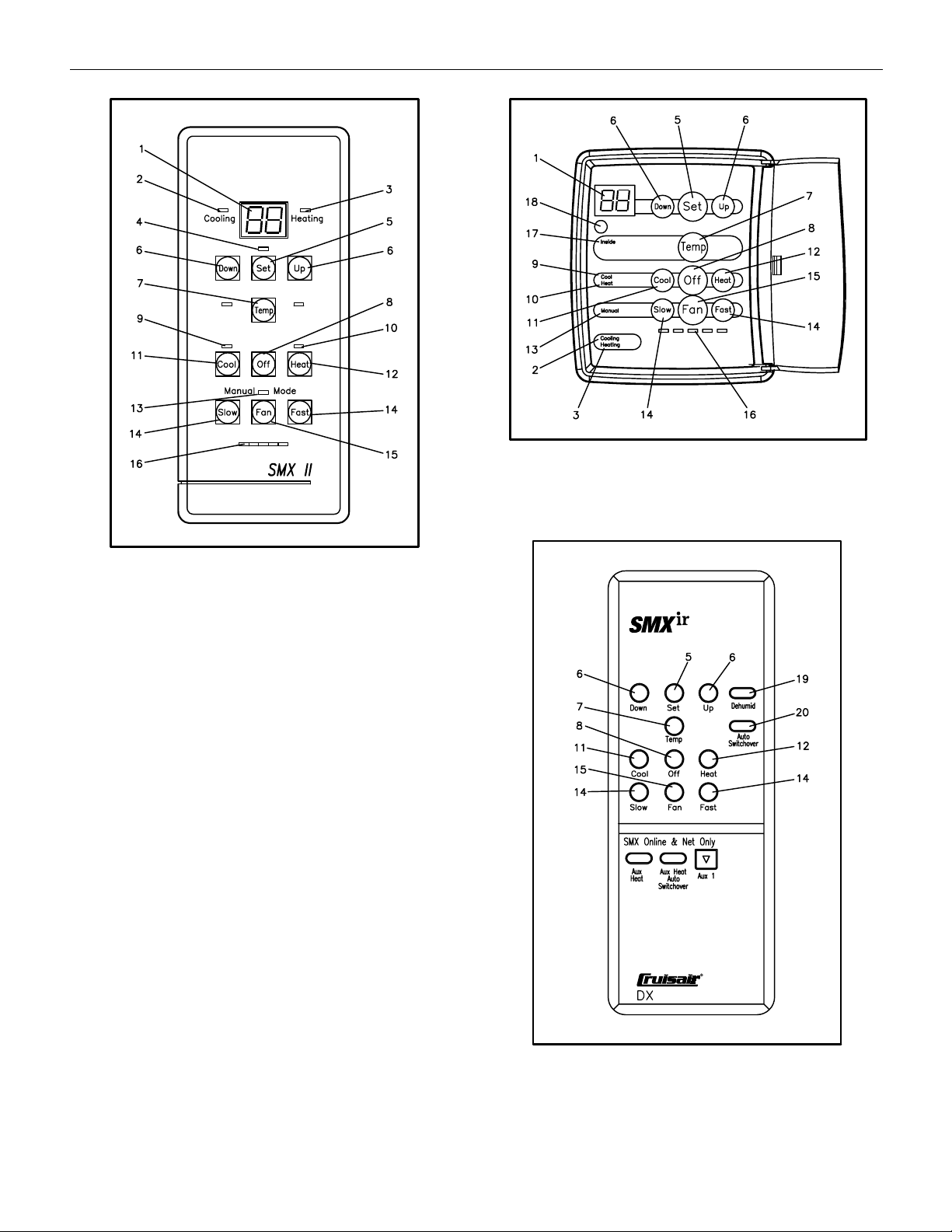
The SMXIIAB & SMXir Keypad/Display
The SMXIIAB and SMXir keypad/displays are designed for
user-friendly, logical operation. The button (or key) arrange-
ments on the SMXIIAB and the SMXir are similar, and these
keys perform the same respective functions. See next page
for keypad/display diagrams.
1. Data Display
Large LED readout which diplays the current setpoint,
temperatures, programmed values and error messages.
2. Cooling Indicator
Lights when compressor is running in Cool Mode.
3. Heating Indicator
Lights when compressor is running in Heat Mode.
4. Setpoint Indicator (SMXIIAB Display Only)
Lights when setpoint is displayed. Off when inside
temperature is displayed.
5. Set Key
Press the Set key to display your currently selected
setpoint (the temperature you wish to maintain in the
cabin). The Set key also is used to dim the Data Display.
6. Up and Down Keys
Press Up or Down to raise or lower the setpoint. Press
and hold keys for large changes. Note: if inside tempera-
ture is displayed, touching the Up or Down key will cause
the setpoint to be displayed.
7. Temp Key
Press once to display inside temperature. Press Temp
twice, and the display will alternate between inside
temperature and setpoint. Press again to return to inside
temperature only.
Hint
You can display temperature in degrees Fahrenheit or Celsius.
8. Off Key
Turns system off. Note that the Data Display remains on.
You can continue to adjust setpoint, display temperature
readings and activate the manual fan to circulate air
while the system is in the Off Mode.
9. Cool Mode Indicator
Lights when you press the Cool key to select the Cool
Mode.
10. Heat Mode Indicator
Lights when you press the Heat key to select the Heat
Mode.
11. Cool Key
Turns the system on in the Cool Mode.
12. Heat Key
Turns the system on in the Heat Mode.
Hint
Press both Heat and Cool at the same time, and the system
will automatically switch between Cooling and Heat Mode.
When in this Automatic Switchover Mode, both the Cool and
Heat indicators are lit.
13. Manual Fan Mode Indicator
Lights when fan is running in Manual Fan Mode.
14. Slow and Fast Keys
Control fan speed when the fan is in the Manual Fan
Mode. Pressing Slow or Fast key when in Automatic Fan
Mode will change the system into Manual Fan Mode.
15. Fan Key
Selects Manual or Automatic Fan Mode. Press once for
manual control. Press Fan again to select automatic fan
speed control. In this mode, the fan speed is controlled
by the microprocessor as a function of the difference
between setpoint and inside temperature. See the Fan
Response Differential programming section.
16. Fan Speed Indicators
Row of five small LEDs below Fan key that indicate the
current fan speed.
17. Inside Temperature Indicator (SMXir Display Only)
When illuminated, inside temperature is displayed. When
light is off, setpoint is displayed.
18. IR Receiver (SMXir Display Only)
Infrared remote receiver.
19. Dehumid Key (Remote Control Only)
Changes system into the Humidity Control Program.
20. Auto Switchover Key (Remote Control Only)
Places the system into Automatic Switchover Mode, so it
will change from cooling to heating as needed.
Definitions
LED - Light Emitting Diode. An indicator light used to denote
mode or operating status.
Setpoint - The desired room temperture that is set by pro-
gramming the SMX control.
IR - Infrared
SMX II Control Systems • Operation
6❖❖
❖❖
❖English
L-2362 Operation
SMXIIAB Keypad/Display
SMXir Keypad/Display
SMXir Remote Control
The SMXir Remote Control
The SMXir remote control keypad has the familiar layout of
the ten button SMX keypad, and performs most of the same
functions. The remote cannot be used to change program
settings. Programming must be done at the keypad/display.
In addition to the standard keys, the SMXir remote also has
two one-touch buttons that allow easy access to the humidity
control program and the Automatic Switchover Mode.
The remote has three buttons that are not used on SMX II
systems. The Aux Heat, Aux Heat Auto Switchover, and the
Aux 1 buttons are for SMX Net systems only.
The SMXir remote control must be pointed at the SMXir
keypad/display, which has the IR remote receiver. The
remote will not work if the SMXir keypad/display has the
optional full coverage door and the door is closed.

7❖❖
❖❖
❖English
L-2362 Operation
Basic Operation
Power On
When AC power is applied to the system at the circuit
breaker, the SMX II microprocessor performs a self-check
and retrieves the last operating configuration from perma-
nent memory. This process takes about four seconds, after
which the system will begin operating just as it had been
when power was last turned off.
System Off
Press the Off key to turn the system off. Note that the Data
Display remains energized even when the system is off. The
fan can be turned on manually when the system is in the Off
Mode.
Note
The SMX II has built-in protection against sudden power in-
terruptions. The system automatically stores the current op-
erating configuration in permanent memory every time any
changes are made. (The new operation mode must be in
affect for 30 seconds before it is saved into permanent
memory.) When AC power is lost, the SMX II system retains
these settings, and when AC power is restored it resumes
operation using the same settings as before.
Selecting Setpoint
Press the Set key and the current setpoint will be displayed.
Press the Up or Down key to change the setpoint.
Displaying Temperature
To display cabin temperature, press the Temp key. Press Temp
twice for an alternating display of inside temperature and
setpoint. Press again to return to inside temperature only.
Cool Mode
Press the Cool key to select Cool Mode. The Cooling Indicator
will light to show that you have selected the Cool Mode.
The Cooling Indicator will be lit whenever the system is in the
Cool Mode and the compressor is running. When the
compressor cycles off, the Cooling Indicator turns off, but the
Cool Mode Indicator remains on.
Heat Mode
Press the Heat key to select Heat Mode. The Heating
Indicator will light to show that you have selected the Heat
Mode.
The Heating Indicator will be lit whenever the system is in the
Heat Mode and the compressor is running. When the
compressor cycles off, the Heating Indicator turns off, but the
Heat Mode Indicator remains on.
Automatic Switchover Mode
Press the Cool and Heat keys simultaneously for Automatic
Switchover between Cool and Heat Modes. Both Cooling
and Heating Indicators will light when the system is in the
Automatic Switchover Mode.
For the SMXir Remote Control only - Press the Auto
Switchover key to enter Automatic Switchover Mode.
Note that the Cooling or Heating Indicator will come on when
the compressor is running to show that the system is running
in the Cool or Heat Mode.
Manual Fan Speed Control
Press the Fan key to select Manual Fan Mode. The Manual
Fan Mode Indicator will light to show that it is in the Manual
Fan Mode. Then use the Slow and Fast keys to select the
desired fan speed.
Note that you can use manual fan control to circulate air
even when the system is in the Off Mode.
Automatic Fan Speed Control
Press the Fan key until the Manual Fan Indicator turns off.
The system is now in Automatic Fan Mode. As the cabin
temperture deviates from the setpoint temperture, the
system will automatically adjust the fan speed. The fan will
increase speed as the difference between the two tempera-
tures increases, and slow down as the cabin temperature
approaches setpoint. Once setpoint is achieved, the com-
pressor cycles off and the fan continues running on low
speed. See the Fan Response Differential programming
section.
Adjusting Brightness
Pressing the Set key repetitively will dim the LED display.
Keep pressing Set to return to full brightness.
Using The Humidity Control Program
When activated, the Humidity Control Program automatically
turns the air conditioning system on at timed intervals to
remove moisture from the air. The system is programmed at
the factory for average values. To change the factory
settings, see the Humidity Control Program section.
To start the Humidity Control Program:
• Press Off.
• Press Cool, Heat and Fan keys simultaneously.
For the SMXir Remote Control only
- Press the
“Dehumid” key to enter Humidity Control Program.
• The Data Display will flash “HU”, indicating that the
program is active.
• To halt the program, press any key. The “HU” message
will stop flashing.

8❖❖
❖❖
❖English
L-2362 Operation
Safety Note
Whenever the system is in the Humidity Control Program, all
of the system safeguard controls remain active. For example,
if the seawater flow fails or if line voltage falls below preset
limits, the system will automatically shut down. Or, if AC
power is interrupted, the system will automatically resume
operation in the Humidity Control Program when power is
restored.
Anti-Ice Routine
The SMX II control will occasionally shut down the compres-
sor in the Cool Mode to allow any ice that may have formed
on the evaporator coil to melt. The Anti-Ice Routine shutdown
will occur only when the inside cabin temperature falls below
70°F (21°C).
During the ten minute cycle period, the compressor will shut
off for 15 seconds for each degree below 70°F. For example,
if the inside temperature is 67°F, the compressor will shut off
for 45 seconds, and then run for nine minutes and 15
seconds, repeating on ten minute intervals.
Seawater Temperature
The basic principle behind an air conditioner is the move-
ment of heat. In an air conditioner, heat is removed from the
inside cabin air and transfered to the seawater. In reverse-
cycle heating, the refrigerant flow is reversed and heat is
extracted from the seawater and discharged into the living
space. The efficiency of the system operation depends on
both seawater and cabin temperatures.
In Cool Mode, the air conditioner will operate most efficiently
in seawater temperatures below 90°F (32°C). At higher
seawater temperatures, the unit will operate, but at a
reduced capacity. A high-pressure shutdown may occur at
higher seawater temperatures.
In Heat Mode, the opposite is true. As the seawater gets
colder, there is less heat available, and the heating efficiency
is reduced. Full heating capacity is obtained at approximately
55°F (13°C) seawater temperature. Performance drops to
about 50% of rated capacity in 40°F (4.4°C) water. Below
this, the system pressure can be so low that the unit will shut
down on low-pressure fault. This problem is compounded
when the cabin is also cold. See the Fault Shutdowns and
Error Messages section.
Warning
Do not operate your air conditioning unit in water that is
colder than 38°F (3.3°C). Doing so could lead to water
freezing in the condenser coil which can cause damage
to the unit.
Programming the SMX II System
SMX II control systems are programmed at the factory for
average values. Some of the programmable functions may
need to be adjusted to suit each individual application and
the operator’s personal preferences. (The SMXir Remote
Control can not be used to program the system.)
To Enter, Use and Exit the Programming Mode
• To enter the Programming Mode: Press Off, then press
Set. Successful entry into the Programming Mode is
indicated by the presence of a decimal point to the right of
the two displayed characters.
• See the following table and each individual program for
specific instructions on using each programmable
function. Press the keys indicated to select that particular
function.
• Once a programmable function has been selected, then
use the Up and Down keys to raise, lower or change its
setting.
• Press Off to exit the Programming Mode.
Compressor Time Delay
(Factory Default: 0 seconds)
This function is used when there is more than one unit on
the boat. To prevent electrical overload due to multiple
compressors starting simultaneously when turning on power
to the system, or when power is interrupted, each SMX II unit
should be programmed with a different Compressor Time
Delay.
Time delay can be set in one-second increments. On older
systems (before 8/98) the time delay is set in ten-second
increments, up to 70 seconds.
• Upon entering the Programming Mode, press the Down,
Set and Up keys simultaneously. The delay in seconds will
be displayed.
At initial power-up, you will see the countdown for each
compressor on the Data Display, if you are in the Temp
Mode. The countdown will not appear in the Set Mode.
Fahrenheit/Celsius Display
(Factory Default: Fahrenheit)
Temperature can be displayed in degrees Fahrenheit or
Celsius.
• Upon entering the Programming Mode, press the Down,
Temp and Up keys simultaneously.
Note
If you switch from Fahrenheit to Celsius for temperature dis-
plays, the Compressor Restart Differential will also operate
on degrees Celsius. Thus, the factory set Compressor Re-
start Differential will be 1.5° Celsius, which is too much. To
correct this, reset the differential value from 12 to 6. This will
provide a differential of 0.75° C, or about 1.4° F.

9❖❖
❖❖
❖English
L-2362 Operation
This will also affect the Fan Response Differential, which is
factory set at a value of 4, or 0.5° Fahrenheit. When chang-
ing from Fahrenheit to Celsius, you should reset the Fan Re-
sponse Differential from 4 to 2. This will provide a fan
differential of 0.25° C, or about 0.5° F.
Compressor Restart Differential
(Factory Default: 12 = 1.5°)
The Compressor Restart Differential is the temperature
change needed for the compressor to cycle on and off. The
factory setting of 1.5° Fahrenheit should be adequate for
most applications. Differential selections are available in
increments of 1/8°. Thus, to change the setting one degree,
you should add or subtract 8 (for 8-eighths). If the tempera-
ture display is changed from Fahrenheit to Celsius, then the
default should be changed from 12 to 6, which is about 0.75°
Celsius.
• Upon entering the Programming Mode, press the Slow
and Fan keys simultaneously. The Compressor Restart
Differential will be displayed.
Hint
Be careful not to set your compressor restart differential too
low, since it will cause the compressor to start and stop quite
often. This will place an undue load on your electrical system
and may shorten the life of the compressor.
Fan Response Differential
(Factory Default: 4 = 0.5°)
When the fan is in the Automatic Fan Mode, its speed is
governed by how much the room temperature differs from
the setpoint. The fan runs faster when the difference is
greater. As the room cools or warms, and the temperature
approaches setpoint, the fan slows down automatically. The
Fan Response Differential can be adjusted from 1/4° to 4°, in
1/8° increments. If the temperature display is changed from
Fahrenheit to Celsius, then the default should be changed
from 4 to 2, which is about 0.25° Celsius.
The fan speed range is divided by the SMX II microproces-
sor into five equal increments. If the Fan Response Differen-
tial is set at 1/2°, then the fan speed will change 20% for
each 1/2° of temperature deviation from setpoint. Lowering
the fan speed differential will cause the fan to change speed
more frequently as temperature changes. Raising the fan
speed differential will result in slower fan speed changes for
a given temperature change. The factory setting of 1/2°
Fahrenheit is good for most applications, but you may wish to
try a slightly higher setting in your salon and a lower setting
in your stateroom.
• Upon entering the Programming Mode, press the Cool
and Slow keys simultaneously. The differential will be
displayed in increments of 1/8°.
Note
If the Compressor Restart and the Fan Response Differentials
are both set to the factroy default, or a comparable range, and
the Automatic Fan Mode is on, then the fan will not run at high
speed unless the cabin temperature rises 2.5° Fahrenheit
above setpoint.
Note
On SMX II systems built before 8/98, press Slow, Fan and Fast
simultaneously to adjust Fan Response Differential.
Low Fan Speed Adjustment
(Factory Default: 38)
You can adjust the lowest fan speed to suit individual
preferences. For instance, you may wish to decrease the low
fan speed setting in your stateroom to minimize fan noise.
• Upon entering the Programming Mode, press the Down
and Set keys simultaneously. The current low speed
reference number will be displayed (factory set
at 38).
Hint
You should normally keep the low fan speed at the highest
possible setting, consistent with a comfortable noise level, for
most efficient operation of your system. Running the fan
speed too slow may have an adverse affect on the system
and may cause the evaporator coil to freeze.
High Fan Speed Adjustment
(Factory Default: 60)
A blower will often reach its highest speed at a voltage lower
than full line voltage. For example, at a line voltage of 120V,
the blower might reach its fastest speed at 110V. At higher
voltages, the bower speed will not increase significantly.
The High Fan Speed Adjustment allows you to set the
maximum high speed voltage to the threshold of the blower
high-speed response. SMX II devides the fan speed voltage
steps into five equal increments (between the low speed and
high speed adjustments). Accurately setting the High and
Low Fan Speed Adjustments can help ensure that each fan
speed increment step results in a noticeable change of fan
speed.
• Upon entering the Programming Mode, press the Set and
Slow keys simultaneously. The current high-speed
reference number will be displayed (factory default is 60).
• While listening to the fan noise level, use the Up key to
raise the displayed value past the point that you can hear
an increase in the fan noise level.
• Press the Down key to lower the voltage until you hear a
drop in fan speed, then raise that number up by 2 or 3 to
ensure that it is set at the highest speed.

10 ❖❖
❖❖
❖English
L-2362 Operation
Fan Mode
(Factory Default: Continuous)
You can select continuous or intermittent fan operation.
Select “C” and the fan will run continuously while the system
is on. Select “I” for intermittent operation and the fan will
cycle on and off with the compressor.
• Upon entering the Programming Mode, press the Down,
Fan and Up keys simultaneously.
Hint
If you select intermittent fan operation, you should relocate the
thermistor from the return air grill to a cabin wall where it can
best sense the average room temperature. Check with your
dealer or call the Cruisair Applications Department for more
information.
AC Line Voltage Calibration
The SMX II control assembly has a built-in voltmeter that
senses AC line voltage. The microprocessor automatically
responds to sustained low-voltage conditions by shutting
down the air conditioning system to prevent compressor
damage. At installation, the SMX II voltmeter should be
calibrated to line voltage within +/- 1%. To check or re-
calibrate AC line voltage:
• Upon entering the Programming Mode, press the Down
and Up keys simultaneously. Line voltage will be displayed
in as the last two digits of the voltage. On 115V systems,
95V appears as “95”, 100V as “00”, and 120V as “20”. On
230V systems the last two digits of 1/2 of line voltage will
be displayed, therefore, 190V will appear as “95”, 200V as
“00”, and 230V as “15”.
• To check accuracy or to calibrate, turn off all on-board AC
loads and measure the line voltage with an accurate
voltmeter.
Temperature Calibration
The temperature sensor should be within one or two degrees
of actual room temperature. To check or re-calibrate the
sensor:
• Upon entering the Programming Mode, press the Set and
Up keys simultaneously. The sensed temperature will be
displayed.
• Place an accurate thermometer beside the sensor and
compare the temperatures.
Factory Memory Reset
Use Factory Memory Reset to restore all programmed
functions to the factory default settings.
To restore programmed functions to the default factory
settings:
• Press the Off, Set and Fan keys simultaneously.
• Press the Set key.
• After a delay, the memory will be reset from stored values.
After another delay, the display will come back on nor-
mally.
Humidity Control Program
The Humidity Control Program automatically operates the air
conditioning system for a programmed time period to help
control humidity in the boat. This dehumidification feature
works in three stages:
1) The fan comes on at high speed to circulate air for ten
minutes.
2) The fan then drops to low speed, and the compressor
cycles on in the Cool Mode to dehumidify.
3) After the dehumidification cycle, the system turns off. The
process repeats according to the programmed time period.
The compressor time delay setting will govern when the
dehumidification cycle starts. Every one-second of compres-
sor delay equals a six-minute advance into the dehumidifica-
tion cycle.
The factory default settings are:
Precirculation cycle ......................... 10 min.
Dehumidification cycle .................... 30 min.
Overall time period ........................... 12 hours
The factory settings are adequate for most moderate
climates and boats. For very humid climates, shorten the
overall time period and extend the dehumidification time. In
dry climates, select longer a overall time period between
cycles and a shorter dehumidification time. The
precirculation cycle time should not be changed.

11 ❖❖
❖❖
❖English
L-2362 Operation
Programming the Dehumidification Time
(Factory Default: 30 minutes)
The dehumidification time determines how long the com-
pressor runs in the Dehumidification Mode. You can select
10, 20, 30, 40, 50 or 60 minutes. Select a longer dehumidifi-
cation time in climates with high humidity.
• Upon entering the Programming Mode, press the Temp
and Set keys simultaneously. The display will show the
dehumidification time period in minutes.
Programming the Overall Time Period
Factory Default: 12 hours)
The overall time period determines how often the system
performs the dehumidification process. You can select
intervals of 2, 4, 6, 8, 10, 12, 14 or 16 hours. Chose a shorter
time period in climates with high humidity.
• Upon entering the Programming Mode, press the Temp
and Up keys simultaneously. The display will show the
overall time period in hours.
Recommended Humidity Control Settings

12 ❖❖
❖❖
❖English
L-2362 Operation
Fault Code Meaning Result
LO / AC Operating voltage remained Shutdown
(or 200V) below 100V for three minutes
for 230V system)
HI / PS* Head pressure above 425 PSI Shutdown
LO / PS* Suction Pressure below 30 PSI Shutdown
PE Program error in software Shutdown
* Note: The “PS” in the high-pressure and low-pressure
fault warning should not be confused as “P5” on the SMX II
LED Data Display.
SMXIIAB & SMXir Keypad/Display Programming Summary Table
Fault Shutdowns and Error Messages
The SMX II control contains built-in safeguards designed to
protect your air conditioning system. These are described
below.
Hint
Your system must be equipped with a high-pressure switch
and low-pressure switch for the high- and low-pressure shut-
down to operate. You should check with your dealer to make
sure these important protective devices are installed properly.
Fault Codes
If an operational failure occurs, the display will flash one of
the following fault code messages. Fault code displays are
cancelled by pressing the Off key.
High-Pressure Shutdown
In the Cool Mode, if head pressure rises above 400-425 PSI
(28-30 kg/cm
2
) (usually caused by loss of cooling water flow,
refrigerant gas overcharge or a fouled condenser) the SMX II
will attempt three restarts, then shut down the entire system.
The display will alternately flash “HI/PS”. This is a sustained
shutdown, and even when the pressure lowers after shut-
down, the system will remain off until reset by pressing the
Off key.
In the Heat Mode, a rise in head pressure above the set limit
(usually caused by poor airflow or incorrect charge) will
cause the compressor to cycle off for two minutes, allowing
the heat in the coil to dissipate. This prepares the system for
recycling in the Heat Mode. The compressor will then
continue to cycle, based on input from the high-pressure
switch, until the cabin temperature reaches setpoint, after
which compressor cycling is automatically restored to normal
operation.
Low-Pressure Shutdown
When installed, the optional low-pressure switch is moni-
tored by the SMX II control. The low-pressure switch opens
when the suction pressure drops below 30 PSI (2.11 kg/
cm
2
), and resets at 45 PSI (3.16 kg/cm
2
). The low-pressure
fault routine operates differently in the Cool and Heat Modes.
Cool Mode:
When the low-pressure switch first opens, the unit will run for
two minutes, then shut down for 50 seconds. It will do this
four times. If the switch has not closed, the unit will shut
Programmable Function Keystroke Combination Factory Setting Range
Compressor Time Delay Down & Set & Up 0 0 to 70 sec.
Fahrenheit/Celsius Display Down & Temp & Up F F or C
Compressor Restart Differential Slow & Fan 12 4 to 24
Fan Response Differential Cool & Slow 4 2 to 8
(Slow & Fan & Fast Before 8/98)
Low Fan Speed Adjustment Down & Set 38 2 to 57
High Fan Speed Adjustment Set & Slow 60 41 to 99
Fan Mode Down & Fan & Up C C or I
AC Line Voltage Calibration Down & Up - ± 1%
Temperature Calibration Set & Up - ± 1%
Factory Memory Reset Off & Set & Fan, then Set
HU Precirculation Temp & Down 10 Min. 10 Min.
HU Dehumidification Temp & Set 30 Min.
HU Overall Time Period Temp & Up 12 Hrs.
See Humidity
Control Program
Note: See the SMXht section for progamming that keypad/display.

13 ❖❖
❖❖
❖English
L-2362 Operation
Likewise, the self-diagnostic routine runs continuously
whenever the SMX II system is on. If a system fault is
detected, the system shuts down, and the “PE” error
message appears.
If this message occurs, contact your nearest Cruisair dealer,
or call the Factory Service Department for assistance.
Please read the next paragraph before calling.
Determining Your Software
Version and Revision Level
Prior to calling a dealer or the factory for service assistance,
it’s helpful to know the software version and revision level for
the SMX II system. To display this information:
• Press Off, then Set.
• Then press the Cool and Down keys simultaneously. The
display will show the version number.
• Press Up once. The display will show the revision level
number.
down for 15 minutes, and alternately flash “LO/PS” on the
display. After 15 minutes of shut down, the cycle stats again
in which the unit runs for two minutes and then shuts down
for 50 seconds.
If, after 18 attempted compressor starts, the low-pressure
switch does not stay closed, the unit will go into a sustained
shutdown and flash “LO/PS”.
If the low-pressure switch closes at any time before the
sustained shutdown, the unit will then operate normally.
Heat Mode:
If the low-pressure switch opens, the fan will automatically
change to low speed to try and raise system pressure. It will run
for 11 minutes in this mode. Note that the fan speed can not be
adjusted at this time. Any attempt to raise fan speed will result in
“LO/PS” being flashed, while the unit continues to run.
After 11 minutes, the unit will run for two minutes, then shut
down for 50 seconds. It will do this four times. If the switch
has not closed, the unit will shut down for 15 minutes, and
flash “LO/PS” on the display. After 15 minutes of shut down,
the cycle stats again in which the unit runs for two minutes
and then shuts down for 50 seconds.
If, after 18 attempted compressor starts, the low-pressure
switch does not stay closed, the unit will go into a sustained
shutdown and flash “LO/PS”.
If the low-pressure switch closes at any time before the
sustained shutdown, the unit will then operate normally.
Low-Voltage Shutdown
The low-voltage protection feature is always active. If AC line
voltage drops and remains below the limit, 100 volts for a
115V system or 200 volts for a 230V system, for more than
three minutes, the SMX II shuts down the entire system. The
display will flash “LO/AC”. This is a sustained shutdown, and
the system will not resume operation even if the line voltage
rises to normal levels. To reset, press the Off key.
Hint
For the low-voltage shutdown function to work properly, the
SMX internal voltmeter should be calibrated. This should be
done when the system is installed. To check or recalibrate
line voltage, see the AC Line Voltage Calibration section.
Software Error
Whenever power is applied to the SMX II, the microproces-
sor goes through an automatic self-check and software
loading process. If all is well, the SMX II loads the most
recent operating configuration from its internal memory, and
turns on normally. If a program fault is found during the self-
check, the error message “PE” (Program Error) will be
displayed.
Initial Start Up
The following instructions apply to both self-contained and
remote condensing systems.
1. Open the seacock (seawater inlet valve).
2. Turn on the circuit breaker for the air conditioner. If a
pump relay is installed, the breaker for the pump must
also be turned on.
3. Set the system for cooling or heating at the SMX II
keypad, and adjust temperature setting so the unit will
turn on.
4. Verify that water is flowing from the overboard discharge.
If more than one unit is installed, then check all such
discharges.
5. Allow unit to run for ten minutes at high fan speed.
Check the temperature differential between discharge
and return air by placing an accurate thermometer in
front of the discharge grill and then in front of the return
air grill.
In the Cool Mode, the difference between the discharge
and return should be 15 - 20°F (8.3 - 11.1°C), with
normal ambient air and water temperatures. In the Heat
Mode the differential can be as high as 25°F (13.9°C).

14 ❖❖
❖❖
❖English
L-2362 Operation
SMXht Keypad/Display Basic Operation
& Programmer's Guide
This section deals specifically with the new SMXht keypad/
display. Much of this keypad/display’s operation and
programming is similar to the older SMXIIAB & SMXir.
General operation and programming is covered in more
detail in the previous sections of this manual, and that
information should be reviewed prior to operating the new
SMXht. The following pages are specific to the new keypad/
display.
Basic Operation
Turning the System On:
Press the POWER or MODE keys to turn the system on. In
three seconds, the system will start operating in whatever
mode it was running prior to the last shut down. Press the
MODE key prior to three seconds (while the display is
flashing) to change mode before system starts, or any time
to change the mode while the system is on. The modes
available are: Cool, Heat Auto Switchover (automatically
switches from Cool to Heat Mode), or Dehumidification
Mode. A solid dot will light up next to the words COOL or
HEAT when the compressor is on and running in that mode.
Selecting the Setpoint:
Press the Up or Down Arrow keys to adjust the setpoint
(press and hold keys to scroll); wait three seconds after
powering up system. The word SET will appear in the display
while setpoint is being adjusted. The setpoint range is 55-
99°F (10-40°C). After selecting the desired setpoint tempera-
ture, if no buttons are pressed for three seconds, the display
will automatically revert back to showing the inside cabin
temperature. Inside cabin temperature is continuously
displayed.
Adjusting the Fan Speed:
The Fan key is used to adjust the fan speed while in Manual
Fan Speed Mode and to switch from Manual to Automatic
Fan Speed Modes. The fan may be run manually whether the
system is on or off. The word MANUAL appears in the
display while in that mode. Automatic Fan Speed Mode may
be operated only when the system is on. Fan behavior also
depends on how the Fan Mode function is programmed - “C”
for continuous or “I” for intermittent running with the compres-
sor (see
SMXht Keypad/Display Programming Summary
Table
).
Dimming the Display:
Press the MODE and Up Arrow keys simultaneously and
repeatedly to select the display brightness setting.
Backlight Mode:
While in the Sleep Mode (backlight is off, see function #20)
press any button to light the display, and then operate as
usual.
Important Memory Function:
After changing modes, programming settings, setpoint, etc.,
wait at least 30 seconds before turning off main power
supply in order for new settings to be maintained in memory.
Programming
SMXht must be in the Off Mode prior to entering Program-
ming Mode; pressing the POWER key turns the display off or
on. Once in the Off Mode, then:
1. Simultaneously press and hold the MODE and Down
Arrow keys for three seconds. The word “PROG” will flash
in the display while the buttons are being held. Success-
ful entry into the Programming Mode is indicated when
the word “PROG” stops flashing, and a flashing “1”
appears in the display.
2. Use the Up or Down Arrow keys to scroll until the desired
program Function Number is displayed. (See
SMXht
Keypad/Display Programming Summary Table
.)
3. Press the MODE key to enter the desired function. The
current value and the word “PROG” will be displayed.
4. Use the Up or Down Arrow keys to change the value of
that program.
5. Press the POWER key to save the new settings, exit the
Programming Mode, and return to the Off Mode.
Note: If SMXht is programmed for displaying °C (rather than
the factory setting °F), then functions 3 & 4 should be
adjusted. For function 3, the factory setting of 12 (or 1.5°F)
should be changed to 7 (7/8 = 0.8°C). For function 4, the
factory setting of 4 (or 0.5°F) should be changed to 2 (2/8 =
0.3°C). For these functions, 1°F (or 8) = 0.6°C (or 5).
SMXht Keypad/Display (shown here with bezel, which is sold
separately).

15 ❖❖
❖❖
❖English
L-2362 Operation
Factory Memory Reset
To restore all programming functions to the Factory Setting,
first switch to Off Mode and then simultaneously press and
hold the POWER and MODE keys. Hold keys for three
seconds while “00” flashes in the display. Successful
memory reset is indicated by a “1” flashing back and forth
across the display; release keys. System returns to the Off
Mode.
NOTE: Performing a Factory Memory Reset will not change
the value of Function Numbers 21 & 22. Also note that
Function Number 2, which displays Fahrenheit or Celsius,
reverts back to °F each time.
Fault Code Displays
If an operational failure occurs, such as low voltage or high/
low pressure, a flashing fault code message will be dis-
played. Fault code displays are canceled by pressing the
POWER key. (See
Fault Code Summary Table
.)
SMXht Keypad/Display Programming Summary Table
Fault Code Summary Table
E
16 ❖❖
❖❖
❖English
L-2362 Troubleshooting
SMX II Quick Troubleshooting Guide
Problem: SMX display not on
Possible Solution:
1. Turn circuit breaker on
2. Check CX/CXP cable and connections
3. Replace keypad/display
4. Replace Power/Logic board
Problem: Erratic temperature display
Possible Solution:
1. Perform a Factory Memory Reset
2. Check temperature sensor, cable and connection
3. Ensure the temperature sensor is installed properly
4. Calibrate temperature
5. Replace Power/Logic board
Problem: Erratic system operation
Possible Solution:
1. Perform a Factory Memory Reset
2. Check CX/CXP cable and connections
3. Check temperature sensor, cable and connection
4. Replace keypad/display
5. Replace Power/Logic board
Warning
The Power/Logic board operates at 115VAC or 230VAC.
Make sure the power is off before removing the cover of
the Power/Logic box.
Contact an authorized Cruisair servicing dealer if the
problem continues, or for replacement parts.
System Troubleshooting
Before you call for service, review this list. It may save you
time and expense. This list contains common occurrences
that are not a result of defective workmanship or materials. If
you need service after trying these procedures, call your
nearest Cruisair dealer.
Situation
The unit will not operate at all.
Problem/Solution
1. Blown fuse or tripped circuit breaker. Replace fuse with
time delay type or reset breaker. Check for correct sizing.
2. Low voltage to unit. Check shore power supply and
rating of electrical power cord to boat.
SMX II Control Systems • Troubleshooting
Situation
Air from the unit does not feel cool in the Cool Mode or warm
in the Heat Mode.
Problem/Solution
1. The selector switch is set for Fan only. Switch the system
into the Cool or Heating Mode.
2. The thermostat is set incorrectly. Set the thermostat for a
cooler or warmer setting.
3. Water flow is restricted. Clear restriction. Clean strainer.
Situation
The unit operates but the cabin fails to cool normally.
Problem/Solution
1. Dirty air filter. Clean lint screen or air filter.
2. The thermostat is set too high. Reset the thermostat to a
cooler setting.
3. The evaporator coil has iced. Turn the system to Fan only
for five minutes, then restart.
Situation
Compressor cycles on and off.
Problem/Solution
1. Dirty air filter. Clean lint screen or air filter.
2. Water flow restriction. Clear restriction. Clean strainer.
Situation
Water dripping inside cabin.
Problem/Solution
1. Condensate drain is clogged. Clean out drain holes.
2. Blockage in hose. Clear hose. Check downhill routing of
hose.

17 ❖❖
❖❖
❖English
L-2362 Maintenance
Condensate Drains
At least once every three months, check the condensate drains
for obstructions by pouring a quart of water rapidly into the
condensate pan. If it does not drain completely within 30
seconds, check the drain outlets for clogging. Remember that
many air conditioning units have two drains and hoses, one at
each end of the drain pan.
Air Filters
At least once a month, check the lint screen or filter behind
the return air grill or on the face of the cooling/heating unit
and clean if necessary.
Seawater Connections
Verify that all seawater connections are tight, and check for
water flow from each unit’s overboard discharge.
Seawater Pump
If the seawater pump has a plastic pump head, then the
impeller is made of either plastic or rubber, and should be
inspected after 300 hours of operation. Replace the impeller
if it is worn. Whereas, if the pumps head is made of bronze,
then the impeller is too, and regular maintenance is not
needed as often.
Seawater Strainer
Check the seawater strainer daily. Remove any debris.
Refrigerant Gas
The refrigerant gas used in the air conditioning system is
adequate for the life of the system. Routine “seasonal”
charging of the system is not typically necessary.
Winterizing the System
Close the seacock and remove the inlet water hose from the
air conditioner. Allow all water to drain from the system.
Loosen the screws on the pump head to allow the water to
drain from the pump. Drain and clean the seawater strainer.
SMX II Control Systems • Maintenance

18 ❖❖
❖❖
❖English
L-2362
Owner’s Warranty Periods
As hereinafter described, Dometic Corporation limits the duration of any implied warranty to the duration of the underlying
express warranty and also disclaims any liability for consequential or incidental damages arising from any application,
installation, use or malfunction of any warranted product.
Section I
What does the Limited Warranty cover?
Products manufactured by Dometic Corporation (Dometic)
are under limited warranty to be free from defects in work-
manship or materials under normal use and service with the
obligation of Dometic under this limited warranty being
limited to replacing or repairing any component(s) which
shall disclose defects within the time limits defined in
Section III and which, upon examination by Dometic, shall
appear to the satisfaction of Dometic to be defective or not
up to specifications.
This Limited Warranty is made in lieu of all other express
warranties, obligations, or liabilities on the part of
Dometic. In addition, Dometic shall not be responsible
for any incidental or consequential damages.
In those
instances in which a cash refund is made, such refund shall
effect the cancellation of the contract of sale without reserva-
tion of rights on the part of the purchaser. Such refund shall
constitute full and final satisfaction of all claims which
purchaser has or may have against Dometic due to any
actual or alleged breach of warranty, either express or
implied, including, without limitation, any implied
warranty of merchantability or fitness for a particular
purpose. Some states do not allow the exclusion or limita-
tion of incidental or consequential damages so the above
limitation may not apply to you. The terms and conditions of
this warranty shall be governed by the laws of the Common-
wealth of Virginia.
The Dealer is not an agent for Dometic except for the
purpose of administering the above warranty to the extent
herein provided, and Dometic does not authorize the dealer
or any other person to assume for Dometic any liability in
connection with such warranty, or any liability or expense
incurred in the replacement or repair of its products other
than those expressly authorized herein. Dometic shall not be
responsible for any liability or expense except as is specifi-
cally authorized and provided in this section.
Dometic reserves the right to improve its products through
changes in design or material without being obligated to
incorporate such changes in products of prior manufacture,
and to make changes at any time in design, materials, or
part of units of any one year's model, without obligation or
liability to owners of units of the same year's model of prior
manufacture.
This warranty gives you, the purchaser, specific legal rights,
and you may also have other rights which vary from state to
state. You also have implied warranty rights, including an
implied warranty of merchantability, which means that your
product must be fit for the ordinary purposes for which such
goods are used.
The duration of any implied warranty
rights is limited to the duration of the express warranty
as found in Section III.
Some states do not allow limitations
on how long an implied warranty lasts, so the above limita-
tion may not apply to you.
Section II
What does this Limited Warranty not cover?
This Warranty Shall Not Apply to:
1. Failures resulting from improper installation or use
contrary to instructions.
2. Failures resulting from abuse, misuse, accident, fire, or
submergence.
3. Any part manufactured by Dometic which shall have
been altered so as to impair its original characteristics.
4. Any parts which fail as a result of misuse, improper
application or improper installation.
5. Items not manufactured by Dometic, i.e., items which are
purchased from another manufacturer and supplied as
received by Dometic without alteration or modification
except as any part of an Dometic-manufactured unit or
component.
6. Components or parts used by or applied by the pur-
chaser as an integral part of products not manufactured
by Dometic.
7. Warranty does not cover damage to components that
comprise a Custom Wrapped Box Evaporator refrigera-
tion system (aka: catch boxes, fish boxes, etc.) when the
box is installed in such a way that the customer can
move it. These damages may include, but are not limited
to: crimped refrigerant linesets (copper tubing or flexible
linesets), refrigerant leaks, moisture ingression into the
refrigeration system, subsequent damage to condensing
unit from being operated with low refrigerant charge or
moisture in the system, broken refrigerant connections,
broken thermostat sensors, and/or broken constant
pressure valves.
Installation and application of Dometic components is not
warranted by Dometic because Dometic has no control or
authority over the selection, location, application, or installa-
tion of these components.
Section III
What is the period of coverage?
See the Limited Warranty Periods, document # L-0694, for
the period of coverage.

19 ❖❖
❖❖
❖English
L-2362
L-0123 Revised: 10-16-03
All Dometic components bear a data plate on which there
are model and serial numbers. The serial number is date
coded. To determine whether or not any Dometic component
is in warranty, proceed as follows:
1. Determine the manufacture date of the component from
the serial number on the data plate. If you are not familiar
with the date code, write or call the Dometic Customer
Service Department at (804)746-1313, to obtain the
manufacture date. The hours of the Customer Service
Department are 8:00 am - 5:00 pm (USA, Eastern Time
Zone) Monday through Friday excluding holidays.
2. It is possible that there might exist a considerable time
lag between the date a component is manufactured and
the date it is put in service. In such instances, the date of
manufacture could indicate that the item is out of
warranty. However, based on the date the equipment is
first put in service, the item may still be covered by the
Dometic warranty described in Section I. For proof of
date put in service, Dometic will require a copy of the bill
of sale of the Dometic equipment from the installer or
new boat dealer to the original owner.
Section IV
How do you get service? Please Read the follow-
ing Warranty Procedure.
WARRANTY PROCEDURE
If the failure of a Dometic component is determined to be
covered under the Dometic warranty and the time in service
is determined to be within the warranty time limit, the owner
has the following three options:
1. Preferred option: Have a Dometic authorized Servicing
Dealer perform the work needed. The customer should
call Dometic's Service Department for a recommenda-
tion as to the closest dealer. If the customer already
knows an authorized servicing dealer, the dealer should
be contacted directly.
2. If the customer contacts Dometic's Service Department
for a Servicing Dealer and Dometic has no one in that
particular area, Dometic will authorize the use of a local
service company and Dometic will work with the local
company to assist in any way possible.
3. The customer may send his equipment back to the
factory to have the repair work done. Dometic will make
every effort to return the equipment to the customer
within a three week time period. If the claim represents a
legitimate warranty problem, Dometic will pay the freight
both ways. Dometic prefers option one and two, if at all
possible.
The customer may contact the Dometic Service Department
at (804) 746-1313.
WARNING
Dometic Corporation (Dometic) manufacturers of Cruisair, Grunert, Marine Air,
Sentry and Tundra Products, makes the following safety warnings concerning the
application, installation, use and care of its products. Although these warnings are
extensive, there may be specific hazards which may arise out of circumstances
which we have not outlined herein. Use this as a guide for developing an
awareness of potential hazards of all kinds. Such an awareness will be a key
factor in assuring your SAFETY and comfort.
ELECTRICITY - Many Dometic products operate on 115, 230 or 440 volt AC
power. Such voltages can be LETHAL; therefore, the chassis, cabinets, bases,
etc., on all components must be grounded together and connected to the vessel's
grounding system. Sparks can occur as switches, thermostats and relays open
and close in the normal operation of the equipment. Since this is the case,
ventilating blowers for the removal of hazardous fumes or vapors should be
operated at least 5 minutes before and during operation of any Dometic product or
group of Dometic products. All electrical connections must be covered and
protected so accidental contact cannot be made by persons using the equipment,
as such contact could be LETHAL.
ELECTROLYSIS - Electrical leakage of any component can cause electrolytic
deterioration (electrolysis) of thru-hull components which could result in leakage
serious enough to sink a vessel which could result in loss of life. All Dometic
components must be kept clean and dry and checked periodically for electrical
leakage. If any electrical leakage is detected, the component should be replaced
or the fault causing the leakage corrected before the component is put back into
service.
GAS - CRUISAIR, MARINE AIR, GRUNERT and TUNDRA components utilize R-22
(Chlorodifluoromethane), R134a refrigerant (Tetrafluoroethane), R-407C (which
contains Diflouromethane (HFC-32), Pentafluoroethane (HFC125), and 1.1.1.2 -
Tetrafluoroethane (HFC134a)), R404A (R125/R143a/R134 (44%/52%/4%)), or
R417a, which are non-toxic, non-flammable gases; however, these gases contain
no oxygen and will not support life. Refrigerant gas tends to settle in the lowest
areas of the compartment. If you experience a leak, evacuate all personnel, and
ventilate area. Do not allow open flames in the area of leaks because refrigerant
gas, when burned, decomposes into other potentially LETHAL gases. Refrigerant
components operate at high pressure and no servicing should be attempted
without gloves, long-sleeved clothing and eye protection. Liquid refrigerant gas
can cause severe frost burns to the skin and eyes.
VENTILATION - To cool or heat air, CRUISAIR, MARINE AIR and GRUNERT
components are designed to move air through a heat exchanger by a blower or
propeller fan. This design necessarily produces a suction on one side of the air
handling component and a pressure on the other side. Air handling components
must be installed so that the suction-pressure action does not: (1) pressurize an
area to the extent that structural failure occurs which could cause harm to
occupants or bystanders, or (2) cause a suction or low pressure in an area where
hydrogen gas from batteries, raw fuel vapor from fuel tanks, carbon monoxide
from operating propulsion engines, power generators or heaters, methane gas
from sewage holding tanks, or any other dangerous gas or vapor could exist. If an
air handling unit is installed in such a manner that allows potentially lethal gases
or vapors to be discharged by the air handling unit into the living space, this could
result in loss of life.
Maximum protection against the introduction of dangerous gases or vapors into
living spaces can be obtained by providing living spaces which are sealed from all
other spaces by use of airtight bulkheads and decks, etc., and through the
introduction of clean air into the living space. Bear in mind that the advent of air
conditioning, whether it be for cooling or for heating, naturally leads to the practice
of closing a living space tightly. Never close all windows and doors unless
auxiliary ventilating systems, which introduce clean outside air into the living
space, are used. Always leave enough window and door openings to provide
adequate ventilation in the event potentially lethal gases or fumes should escape
from any source.
CONDENSATE - All cooling units produce water condensate when operating on
the cooling cycle. This water must be drained from the cooling unit overboard. If
condensate is allowed to drip on a wooden structure, rotting or decay and
structural failure may occur which could result in loss of life. If condensate is
allowed to drip on electrical components, deterioration of the electrical compo-
nents could result in hazardous conditions. When an air conditioning system is in
operation, condensate drains may be subjected to negative pressure. Always
locate condensate drains as far as possible from points where engine waste and
other dangerous gases are exhausted so no such dangerous gases can be drawn
into the condensate drains.
Warning
Never sleep in a closed area on a boat when any equipment, which functions as a
result of the combustion of a volatile fuel, is in operation (such as engines,
generators, power plants, or oil-fired heaters, etc.). At any time, the exhaust
system of such devices could fail, resulting in a build-up of LETHAL gases within
the closed area.
20 ❖❖
❖❖
❖English
L-2362
* The box denotes the part of the warranty that pertains to this particular product.
Please read and keep this document with your important paperwork. Use it as a reference in the future. If you have any
questions, please contact the Dometic Corporation Service Department at (804)746-1313 for clarification.
Note: Any model or replacement part that has been installed due to a warranty failure will carry onlythe remainder of the
original warranty. All warranties begin when the customer takes possession of the equipment. The warranty is extended to all
owners of the equipment commencing the date the original owner takes possession of it. Proof of original purchase may be
required. Fuses and MOV’s are used as safety devices to protect Cruisair equipment against over-current conditions caused by
lightning or inductive switching environments. These are not covered under warranty. We reserve the right to change our
warranty policies and procedures as well as our warranty allowances without notice.
Cruisair Direct Expansion (DX)
and Modulating Systems
• New, complete system installation using any member of
the SMX family.
The warranty includes the pump.
2 year warranty including Parts and Labor
• New, complete system installation using an electro-
mechanical control (3-knob).
The warranty includes the pump.
1 year warranty including Parts and Labor
• New, complete model sold as a partial system retrofit to
an existing system.
Includes SMX family.
1 year warranty including Parts and Labor
Cruisair Tempered Water
• New, complete system installation using any member of
the SMX family.
2 year warranty including Parts and Labor
NOTE: Excludes pump which has a 1 year warranty
• New, complete model sold as a partial system retrofit to
an existing system.
Includes SMX family.
1 year warranty including Parts and Labor
Sentry Battery Chargers
• New SM and FR series installation.
2 year warranty including Parts and Labor
• New G-series installation.
1 year warranty including Parts and Labor
Refrigerators/Freezers/Fish Boxes
The below warranty periods do not apply to systems that are
installed as described in Section II, item #7, of the Owner’s
Limited Warranty, document # L-0123.
• New installation of entire system including condensing
unit, line sets, evaporator, etc.
1 year warranty including Parts and Labor
• New complete model sold as a partial system retrofit to an
existing Cruisair system.
1 year warranty including Parts and Labor
• New installation of condensing unit only, with line sets,
evaporators, etc. done by others i.e. not Cruisair pre-
charged line sets and evaporators.
1 year warranty including parts and labor on
mechanical and electrical parts of condensing unit
only.
Replacement Parts
• Replacement parts and components - example: A-509,
40401-30.
90 day warranty, Parts only
• Replacement Compressors for other than Tempered
Water Systems - example: R3101-16T, DX equipment -
installed in an existing Cruisair system or a competitor’s
system.
1 year warranty including Parts and Labor
• Replacement compressors for Tempered Water - example:
30130-36 installed in an existing Cruisair system.
1 year warranty including Parts and Labor
• A Tempered Water compressor - example: 30130-36
installed with competitor’s equipment.
90 day warranty, Parts only
Revised: 8-19-04 L-0694
Limited Warranty Periods
This manual suits for next models
2
Table of contents


