Cruise control AP900Ci Operating and maintenance instructions

ORANGE
CAN-BUS CONNECTION
BLUE/ WHITE
BLUE
Accelerator
Control Module (CM)
Ignition
+12V
1
T-harness
Diagnostic
socket
CAN High
pos. 6
CAN Low
pos. 14
Engine control
module
OBD
connector
OBD connector is most
common connection point of
CAN-bus wires
By installation refer
connection points
shown on model specific
installation manual
of Beijer Automotive
delivered with the system!
The OBD adapter supplied
with the GC90Ci kit must
not be used. Wires must be
soldered behind the OBD
connector!
Model specic T-harness
will be connected between
connectors of accelerator
pedal
If analog inputs activated
connect them like described
on chapter 8 and 9.
ProTeam OÜ
Männiku tee 104,
11216 Tallinn, Estonia
Tel: +372 672 6308
www.proteam.ee
CRUISE CONTROL AP900Ci/ GC90Ci
QUICK INSTALLATION MANUAL

AP900Ci/ GC90Ci quick installation manual ProTeam OÜ
1Switch ignition ON.
2Switch speed limiter ON (push CM back)
4Press and release brake pedal 4 times,
then release SET
Buzzer sounds 1 low 2 high tones
Buzzer sounds 4 low tones
7
4x high + low tones 4x high tones
Test not passed.
Check if the right
vehicle is selected for
programing and repeat
the test. Sometimes will
test pass easier if on step
1 to start the engine.
OK! Test passed –
go to chapter 3
Pedal Learning Mode
SOFTWARE UNLOCK
Always required!
2
6
3Press and hold SET (lift CM up and hold)
SET
ON
Now will buzzer give in series 3 long beeps.
Immediately press brake pedal when beep starts.
Immediately release brake pedal when beep stops.
5
Until software isn’t unlocked
is the tone of audible signals
vibrating.
When software is
unlocked is the tone of
audible signals clear
Look software unlock video:

AP900Ci/ GC90Ci quick installation manual ProTeam OÜ
PEDAL LEARNING MODE
Always required!
Switch ignition ON.
(don’t start the
engine)
Switch speed limiter
ON (push CM back)
Press and hold the
BRAKE pedal
Press the SET key
4 times
(lift CM up 4x)
Press the RES key
1 time
(press CM down 1x)
Release BRAKE
pedal
Press the SET key
1 time
(lift CM up 1x)
Gently press the accel-
erator to full throttle
(by some cars 95%*)
1X
HIGH
HIGH
LOW
HIGH
LOW
. . .
1X
LOW
4x
HIGH
LOW
LOW
LOW
. . .
Press the SET key
4 times
(lift CM up 4x)
Press 1x RES key
(press CM down 1x)
Release accelera-
tor pedal
Press and hold the
BRAKE pedal
Release BRAKE
pedal
Pedal learning
performed
If the
programming
does not
go through
as described or the
tones do not match,
start programming from
beginning.
* Pressing the pedal
95% is easy if to insert
a piece of cardboard
under the pedal
3
1X
LOW
2X
HIGH
Installation is done!
Go to test drive.
1X
HIGH
LONG
HIGH

AP900Ci/ GC90Ci quick installation manual ProTeam OÜ
DIAGNOSTIC MODE
Optional!
4
Test 1: switch ignition ON
Test 2: start engine
Switch speed limiter
ON (push CM back)
Release SET key
Press and hold
SET key
(lift CM up)
1X
LOW
Diagnostics 1:
CM, brake signal,
clutch signal
Operate every function of CM: lift up,
press down, pull forward, press memory
buttons- the system must respond to
every action with beep signal.
If there no signal check CM and
the wiring of it.
Press brake pedal- the system must
respond with beep signal.
If there no signal check connection of
CAN wires or by analog connection check
brake wires.
Press clutch pedal- the system must
respond with beep signal.
If there no signal use
clutch pedal switch.
Diagnostics 2:
Accelerator pedal control,
vehicle speed signal
Press and hold SET key- wait until engine
speed increases. Release set and press
brake pedal- engine speed drops idle.
Press and hold SET key- wait until
engine speed increases.
Release SET - engine speed
remains on constant level.
Press and hold RES key- engine speed
decreases.
If not perform pedal learning.
Drive at least 30 km/h - when speed
signal is received will the system give
pulsating beep signals and the led on
the central unit is ashing
If not check CAN wires or learn speed
or use analog speed signal.
Switch the ignition completely OFF to
exit Diagnostics
Switch the ignition completely OFF to
exit Diagnostics

AP900Ci/ GC90Ci quick installation manual ProTeam OÜ
INIT ADJUSTMENT Optional
Release BRAKE
pedal.
Drive at least 40
km/h
Press SET key 1
time
(lift CM up)
3X
HIGH
LOWER
3X
LOW
HIGH
With the init can be adjusted how aggressive or slow the limit speed is reached.
When the init is set to high, it will rst go over the limit speed and then slow down again and stabilize at
the limit speed. When the init is set to low, it will rst slow down a bit and then stabilize at the limit speed
Press RES 1x -
init decreases 1 step
HIGHER
Press SET 1x -
init increases 1 step
Press SET key 4
times
(lift CM up 4x)
Press briey
BRAKE pedal
Stop safely the
vehicle
Press and hold
BRAKE pedal
Release BRAKE-
setup completed.
LONG
HIGH
2X
HIGH
5
Switch ignition ON.
(don’t start the
engine)
Switch speed limiter
ON (push CM back)
Press and hold the
BRAKE pedal
Press SET key 4
times
(lift CM up 4x)
4x
HIGH
1X
LOW
2X
HIGH
Press 3x RES key
(press CM down 3x)
By every press of CM system responses with number
of beeps corresponding to activated init level

AP900Ci/ GC90Ci quick installation manual ProTeam OÜ
6GAIN ADJUSTMENT Optional
Whit the gain can be adjusted how the limiter will react driving on the limit speed.
When the gain is set to high the speed will be steady but you will feel the throttle all the time.
When the gain is set to low the limiter will be continuously moving around the limit speed.
Release BRAKE
pedal.
Drive at least 40
km/h
Press SET key 1
time
(lift CM up)
3X
HIGH
LOWER
3X
LOW
HIGH
Press RES 1x -
gain decreases 1 step
HIGHER
Press SET 1x -
gain increases 1 step
Press SET key 4
times
(lift CM up 4x)
Press briey
BRAKE pedal
Stop safely the
vehicle
Press and hold
BRAKE pedal
Release BRAKE-
setup completed.
LONG
HIGH
2X
HIGH
Switch ignition ON.
(don’t start the
engine)
Switch speed limiter
ON (push CM back)
Press and hold the
BRAKE pedal
Press SET key 4
times
(lift CM up 4x)
4x
HIGH
1X
LOW
2X
HIGH
Press 4x RES key
(press CM down 4x)
By every press of CM system responses with number
of beeps corresponding to activated gain level

AP900Ci/ GC90Ci quick installation manual ProTeam OÜ
1Switch ignition OFF
2Press and hold SW1 of central unit
3Switch ignition ON
5Press and hold brake and clutch pedal (if exists),
press SET key 1 time (lift CM up 1x)
2 beeps
1 beep signal, LED on central
unit ashes
Central unit searches CAN signals
71 long beep 3 short beeps
CAN-signals not found.
Repeat the procedure.
OK! CAN-signals found
Release pedals, switch
ignition OFF.
To complete setup perform
Software unlock (Ch. 2)
CAN SEARCH. Needed to perform only when
chapter 2 ”Software unlock” will not succeed.
7
6
4Release SW1
SET
When chapter 2 “Software unlock” will not succeed try to nd suitable CAN software with CAN search
function. CAN search is successful only if suitable software is stored to internal memory of speed
limiter. Because of limited capacity not every software is stored to internal memory. If CAN search
isn’t successful go to step 8 and install limiter using analog signals.
If CAN-signals found but
system still doesn’t work
press on that point SET key
once- system will start to
search next suitable CAN-
software.

AP900Ci/ GC90Ci quick installation manual ProTeam OÜ
ACTIVATING ANALOG MODE
Perform only if CAN signals not available!
8
When analog mode activated must analog wires be connected according chapter 9.
Press and hold SW1 of
central unit and
switch ignition ON
ON
Switch speed limiter ON -
2 beeps, release SW1
In analog mode must in addition to T-harness be connected following wires:
ORANGE ignition (+12V when ignition switched ON)
BLUE vehicle speed pulse (ground pulses which frequency depends of vehicle speed)
BROWN hot side of brake switch (+12V always or when ignition ON)
BROWN/WHITE cold side of brake switch (+12V when brake pedal pressed)
VIOLET clutch switch wire whree state of ground will change when pedal is pressed (usually grounded when
pedal is peressed but is working also when grounded when pedal is not pressed).
Main diagram on chapter 9
When all wires are connected must be performed following setup steps:
Chapter 3: Pedal learning
Chapter 10: Learning of speed signal
Optionally can be performed chapter 4 diagnostic and chapter 5 and 6: init and gain adjustment.
If speed limiter is in analog mode but it’s needed to activate CAN mode just perform CAN search according chapter 7.
When CAN software will be found turns limiter to CAN mode and starts to work without performing “Software unlock”.
RES x 1
Press RES key once
(CM down):
4 short beeps
ANALOG MODE
IS ACTIVATED
2x
HIGH
4x
HIGH

AP900Ci/ GC90Ci quick installation manual ProTeam OÜ
ORANGE
ANALOG CONNECTIONS
Brake pedal
Speed pulse
BROWN/ WHITE
BROWN
BLUE
YELLOW
Yellow wire is not in use.
If on dedicated installation manual is
recommended to use pul-up resistor to boost
speed signal connect the resistor between
Orange and Blue wire.
Resistor
NOISE SUPPRESSER
DO NOT REMOVE
Ignition
+12V
9
Accelerator
pedal
High
signal
(voltage) of
accelerator
pedal
Ground of
accelerator
pedal
YELLOW
BROWN
RED
WHITE
GREEN
If model specic T-harness is used connect it like
shown on chapter 1.
Above is shown most common connection of
universal pedal harness.
On wire of high signal of accelerator pedal is
usually (but not always) 2 times or 0,7V higher
voltage than on low signal wire.
For example could the voltages on signals wires
be in idle - full throttle position:
High signal: 1,4V - 4,0V
Low signal: 0,7V - 2,0V
or
High signal:1,3V - 4,2V
Low signal: 0,6V - 3,5V
Control Module (CM)
Engine control
module
Low
signal
(voltage) of
accelerator
pedal
Clutch pedal
VIOLET

AP900Ci/ GC90Ci quick installation manual ProTeam OÜ
LEARNING OF SPEED SIGNAL
Switch ignition ON
and start the engine
Switch speed limiter
ON (push CM back)
Press and hold the
BRAKE pedal
Press the SET key
4 times
(lift CM up 4x)
Press the RES key
2 times
(press CM down 1x)
Release BRAKE
pedal
Drive 72 km/h Press the SET key
1 time
(lift CM up 1x)
2X
HIGH
2X
LOW
4X
HIGH
Press SET key 4
times
(lift CM up 4x)
Press briey BRAKE
pedal
Stop safely the
vehicle
Press and hold
BRAKE pedal
Release BRAKE-
setup completed.
Procedure
completed
10
Learning of speed signal must be
performed in analog mode but with
the same procedure is possible to
calibrate speed signal also in CAN
mode.
2X
HIGH 4X
HIGH

AP900Ci/ GC90Ci quick installation manual ProTeam OÜ
The Cruise Control is equipped with an error code generator. In case Cruise Control switches o or does not switches
on for an abnormal reason will error code indicated with beeps:
Number of
beeps Description of error
1 control function is pressed for more than 20 seconds
2 acceleration speed is more then 9 kph per second
3 speed drops below 33 km/h
4 speed exceeds 250 km/h
5 speed drops below 75% of the current set speed
6 speed exceeds 150% of the current set speed
7 throttle pedal not calibrated
8 speed increases abnormally
ERROR CODES
11
This manual suits for next models
1
Table of contents
Popular Automobile Accessories manuals by other brands
Horn Tools
Horn Tools HSW995GRAPPLATE Mounting instructions
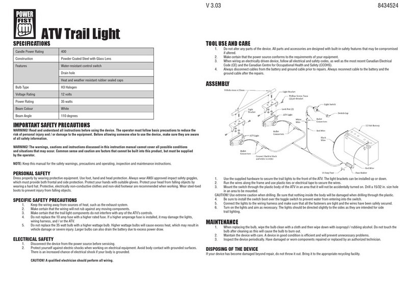
Power Fist
Power Fist 8434524 quick start guide
Nex-tech
Nex-tech GPS Speedometer Head Up Display quick start guide
Caraudio-Systems
Caraudio-Systems RL-LR17-TF manual
Let's Go Aero
Let's Go Aero HexCap manual
Air Lift
Air Lift Performance 3P installation guide
