Shurco ShurCover User manual

Sheeting System w/SMART3™
P/N 1127925

Shur-Co®, LLC Terms & Conditions
SHIPPING. Orders are shipped F.O.B.
from the Shur-Co®, LLC sites listed below. No full freight is
allowed or prepaid shipment accepted unless quoted and approved in
writing prior to acceptance of the order. All shipments are made by the most
reasonable means in accordance with size and weight of order, unless speci-
fi ed routing instructions are furnished by the customer. Shipments are made
daily via courier. Claims for shortages must be made within 10 days. All claims
for damages or loss in transit must be made with the carrier. No collect calls
will be accepted. To ensure delivery of orders, we need your full street address
and phone number. When you receive your shipment, examine it carefully. Be
sure all cartons listed on the delivery sheet are accounted for. Large items may
be packaged separately. If a carton is damaged, open it and inspect the con-
tents before signing for delivery. If merchandise is damaged, describe damage
on the delivery receipt. Failure on your part to document damaged or missing
merchandise on the delivery receipt releases the carrier of all liability; repair or
replacement will be the customer’s responsibility.
WARRANTY. We warrant all new products are free of defects in materials and
workmanship.* This warranty is effective if products are properly installed and
used for the purpose for which they were intended and applies to the original
buyer only. Except as set forth above or in any product-specifi c warranty docu-
mentation, we make no other warranties, express or implied, including but not
limited to warranties of merchantability of fi tness for a particular use.
Returns of a product for warranty must be accompanied by a Return Mer-
chandise Authorization number (RMA#), obtained by by calling UK Customer
Service at 01795 473499, and sent, with freight paid by us, to Shur-Co®UK
Ltd., Donovan House, Unit 41, Rochester Airport Estate, Rochester, Kent ME1
3QX. All products returned without an RMA# will be refused. When we issue
the RMA#, we will also issue a call tag to have UPS (or other freight company)
pick up the product. C.O.D. returns not accepted. We will pay no storage fees
for a warranty product return prior to pick by us or the freight company. If a
warranty product return is scheduled to be picked up by us, we will pick up the
product at our earliest convenience.
If a product returned is found, in our judgement, to be defective in material
or workmanship, our obligation under this warranty is limited to the repair or
replacement of the product, which will be made by us. Repair or replacement
will be at our discretion, with replacements being made using current products
performing in the equivalent function. Labor charges, other than those incurred
at our factory, including, but not limited to, any labor to install a repaired or re-
placement product, are not covered under this warranty. All expenses associ-
ated with delivering defective products to our factory and delivering repaired or
replacement products from our factory to the owner will be paid by us.
If the product returned is found, in our judgement, to be non-warrantable, the
owner will be contacted to authorize repair work, purchase of a replacement
product or return of the product, all of which will be at the owner’s expense.
Payment authorization must be received by us before any non-warrantable
product is repaired, replaced or returned. All expenses associated with deliver-
ing the repaired non-warrantable product, a replacement product or the non-
warrantable product from our factory to the owner will be paid by the owner.
In no event will we be liable for any damages of any kind to person, product or
property, including but not limited to indirect, incidental, special, consequential
or punitive damages, or damages for loss of profi ts or revenue, even if we
have been advised of the possibility of such damages. There are no warran-
ties for used products or products that have been repaired, altered, modifi ed
or subjected to misuse, negligence or accident. We will not repair or replace
products that fail or malfunction due to ordinary wear and tear, except as ex-
pressly noted in a product-specifi c warranty. Use of non-Shur-Co®, LLC parts
in conjuction with Shur-Co®, LLC products will void this product warranty.
*Certain products have specifi c warranties that differ from this warranty, for example motors and elec-
tronics. Product-specifi c warranty documentation is available for these items. In the event of a confl ict
between this warranty and a product-specifi c warranty, the product-specifi c warranty will govern.
RETURN POLICY. All sales fi nal. See WARRANTY above for return details.
OTHER. All prices, product listings, sizes, weights and manufacturing details
are subject to change without notice. No person is authorized to modify the
foregoing conditions of sale whatsoever.
SHUR-CO® of NORTH DAKOTA
1746 4th Ave. NW
West Fargo, ND 58078
Ph 877.868.4488 | Fax 701.277.1283
SHUR-CO® of OHIO
1100 N. Freedom, St. Rt. 88 & 14
Ravenna, OH 44266
Ph 866.356.0242 | Fax 330.297.5599
SHUR-CO® of TEXAS
34505 I-10 West, S. Frontage Rd.
Brookshire, TX 77423
Ph 866.689.0039 | Fax 281.934.3311
SHUR-CO® UK, Ltd.
Unit 41 Rochester Airport Estates
Laker Rd., Rochester, Kent ME1 3QX
Ph +44 (0)1795.473499
Fax +44 (0)871.272.8278
For more info, log on to our website:
www.shurco.com
Corporate HQ and Outlet Store
SHUR-CO® of SOUTH DAKOTA
2309 Shur-Lok St., PO Box 713
Yankton, SD 57078-0713
Ph 800.474.8756 | Fax 605.665.0501
ShurTite™ Service Centers
SHUR-CO® of CANADA
490 Elgin St., Unit #1
Brantford, Ontario N3S 7P8
Ph 800.265.0823 | Fax 519.751.3997
SHUR-CO® of SIOUX FALLS
47184 258th St., Suite B
Sioux Falls, SD 57107
Ph 844.573.9322 | Fax 605.543.5469
SHUR-CO® of ILLINOIS
Ph 866.356.0246 | Fax 217.877.8270
SHUR-CO® of OHIO
Ph 866.356.0242 | Fax 330.297.5599
SHUR-CO® of COLORADO
10220 Brighton Rd., Unit #1
Henderson, CO 80640
Ph 866.355.9173 | Fax 303.289.2298
SHUR-CO® of FLORIDA
3353 SE Gran Park Way
Stuart, FL 34997
Ph 800.327.8287 | Fax 772.287.0431
SHUR-CO® of ILLINOIS
3993 E. Mueller Ave.
Decatur, IL 62526
Ph 866.356.0246 | Fax 217.877.8270
SHUR-CO® of IOWA
3839 Midway Blvd.
Ft. Dodge, IA 50501
Ph 866.356.0245 | Fax 515.576.5578
SHUR-CO® of MICHIGAN
5100 Lakeshore Dr.
Lexington, MI 48450
Ph 800.327.8287 | Fax 772.287.0431
SHUR-CO®, LLC SERVICE AND DISTRIBUTION CENTERS
P/N 1124308 Rev. D

UK HELP LINE: +44 (0) 1795 473499
Thank you for buying this sheetinging system from Shur-Co®We ap-
preciate your condence in our products. Please read and thoroughly
understand this manual before installing and/or operating this system.
Pay particular attention to important safety and operating instructions,
as well as warnings and cautions. The hazard symbol is used to
alert users to potentially hazardous conditions and is followed by cau-
tion, warning or danger messages.
Failure to READ AND FOLLOW INSTRUCTIONS could result in fail-
ure of your system and/or personal injury. Your trailer requirements
may, however, call for minor variations to these instructions.
Please inspect your sheeting system periodically; repair or replace
worn or damaged parts.
QUESTIONS? CALL OUR HELP LINE:
+44 (0) 1795 473499
MON-FRI 8 AM-5 PM CENTRAL TIME
We at Shur-Co® are concerned with your safety and the safety of all
those operating this system. Therefore, we have provided safety de-
cals at various locations on your sheeting system. Keep decals as
clean as possible at all times. Replace any decal that has become
worn or damaged, painted over or otherwise difcult to read. Replace-
ment decals are available through Shur-Co® dealers.
SAFETY INSTRUCTIONS
To prevent rust, paint all exposed metal, such as weld seams and/or
metal exposed by grinding or cutting, with corrosion-resistant paint.
ShurCover Sheeting System
P/N 1127925
!
MESSAGE TO OWNERS
SAFETY
RUST PREVENTION
Hardware Identication/Box Preparation..................................... 1
Sheet Installation...................................................................... 2-3
Center Pole Drive Motor.............................................................. 4
Web Spool & Drive Motor......................................................... 5-8
SMART3™ Wireless Receiver ............................................... 9-13
System Setup ....................................................................... 14-16
Replacement Parts............................................................... 17-20
1. Aluminum Welder
2. #3 Phillips Insert Bit or #3 Phillips Screwdriver
3. Band Saw or Hack Saw
4. Torque Wrench
5. Socket Wrench
6. 17mm Socket
7. 17mm Combination Wrench
8. 8mm Socket or Nut Driver
9. 1/2" Socket
10. 19mm Socket
11. 19mm Combination Wrench
12. Tape Measure
13. Pencil
14. Electric Drill
15. 8mm Drill Bit (for 3/8" self-tapping screws)
16. 10mm Drill Bit (for 3/8" cap screws)
17. Air or Electric Wrench w/9/16” Socket
18. 9/16" Combination Wrench
19. 9/16" Socket
20. 5mm Drill Bit
21. 1/2" Combination Wrench
22. #2 Phillips Screw Driver
23. 3/8" Hex Driver
24. Wire Crimp Tool
25. 13mm Socket
26. 10mm Socket
Optional: Hot Knife, Spray Paint, Caulk or Rubber Sealant
TABLE OF CONTENTS
TOOLS REQUIRED
1.
Always wear safety glasses during installation.
2. Keep body and clothing clear of moving parts.
3. Use only OSHA-approved ladders or scaf-
folding during installation process.
4. No other use of this system is authorized,
except as designed.
SAFETY INSTRUCTIONS

UK HELP LINE: +44 (0) 1795 473499
P/N 1127925
Hardware Identication
1
1700398 - Self-Drilling Screw - 1/4" x 3/4"
1705461 - Cap Screw - M12 x 1.75 x 130
1705355 - Cap Screw - M10 x 1.5 x 150
1700407 - Hex Nut - 3/8"
1705556 - Cap Screw - M10 x 1.5 x 65
remove sharp edges on top
rail - paint all exposed metal
C
D
E
F
G
B
M
N
A
H
1704338 - Self-Tapping Screw - 1/4" x 1"
1704931 - Flanged Nylon Lock Nut - 5/16"
1705378 -
Self-Tapping Screw - 5/16" x 3/4"
1705357 - Cap Screw - M10 x 1.5 x 45
- CL10
1700419 - Nylon Lock Nut - 5/16"
CAUTION
Box extensions (tip tops), if used, must be
secured to truck box. System could blow off if
box extensions are not secured to box.
!
SHEET INSPECTION
BOX PREPARATION
Measure sheet. Determine sheet length and width with slight
tension applied. Compare with length and width stated on paper
attached to sheet. If sheet length and width do not match what
is on paper, do not proceed. Call your local dealer or call Shur-
Co® Customer Service at +44 (0) 1795 473499.
Prepare body before installing ShurCover sheeting system. Re-
move or grind any sharp edges smooth to prevent sheet dam
age.
To prevent rust, paint all exposed metal, such as weld seams
and/or metal exposed by grinding or cutting, with corrosion-
resistant paint.
1700434 - Lock Washer - 3/8"
O
1705371 - Cap Screw - M5 x 12
1700428 - Flat Washer - 5/16"
P
Q
1705350 - Lock Washer - M10
1705347 - Fender Washer - 10.5 x 30
V
W
X
1705361 - Nylon Lock Nut - M10 x 1.5 -
CL10
1705373 - Nylon Lock Nut - M12 x 1.75
T
1701176 - Flat Washer - 3/8"
U
1705555 - Nylon Lock Nut - M10 x 1.5
Y
1700400 - Self-Tapping Screw - 3/8" x 1"
1702926 - Cap Screw - 5/16" x 7/8"
S
Z
I
1705370 - Cap Screw - M10 x 1.5 x 60 - CL10
1705353 - Machine Screw - M6 x 10
1705349 - Nylon Lock Nut - M8 x 1.25
1705550 - Carriage Bolt - M8 x .50
1705551 - Flanged Cap Screw - M6 x 16
R
L
K
J
1705376 - Flanged Cap Screw - M5 x 16
a

UK HELP LINE: +44 (0) 1795 473499
P/N 1127925
2
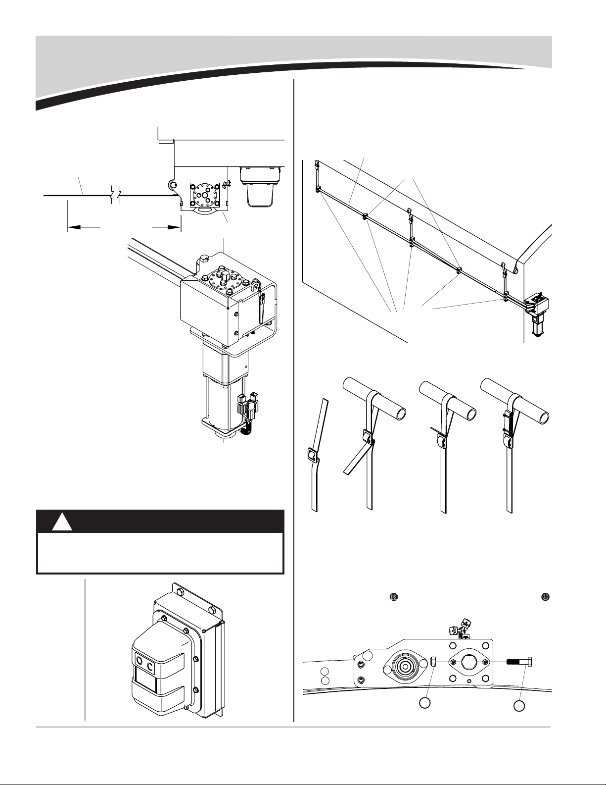
STEP 2: Install double
support arch if
required (not
supplied).
Sheet Installation
STEP 3: Cut center pole, pull bar and xing bar to length. Add
holes per print.
STEP 4: Verify ends of center pole are cut at 90°.
STEP 5: Insert center pole plug assembly into center pole.
Make sure face of assembly is square to center pole.
STEP 6: Weld center pole plug assembly onto end of center
pole.
NOTE: Keyway
must be 180°
from 5mm hole.
cut to length
90°
keyway
hole
center pole
plug
6.5 x3.5
Item Part # Description
1. 1123980 Center Pole Plug - UK
2. 1701354 U-Clamp
3. ______ Center Pole
4. ______ Pulling Bar
5. ______ Fixing Bar
6. ______ Sheet (not shown)
D. 1700398 Self-Drilling Screw - 1/4" x 3/4"
1
2
3
5
4
STEP 1: Install plastic
sheet to both
hoods (not
supplied).
uhmw
D
UK HELP LINE: +44 (0) 1795 473499
P/N 1127925
3
Sheet Installation - continued
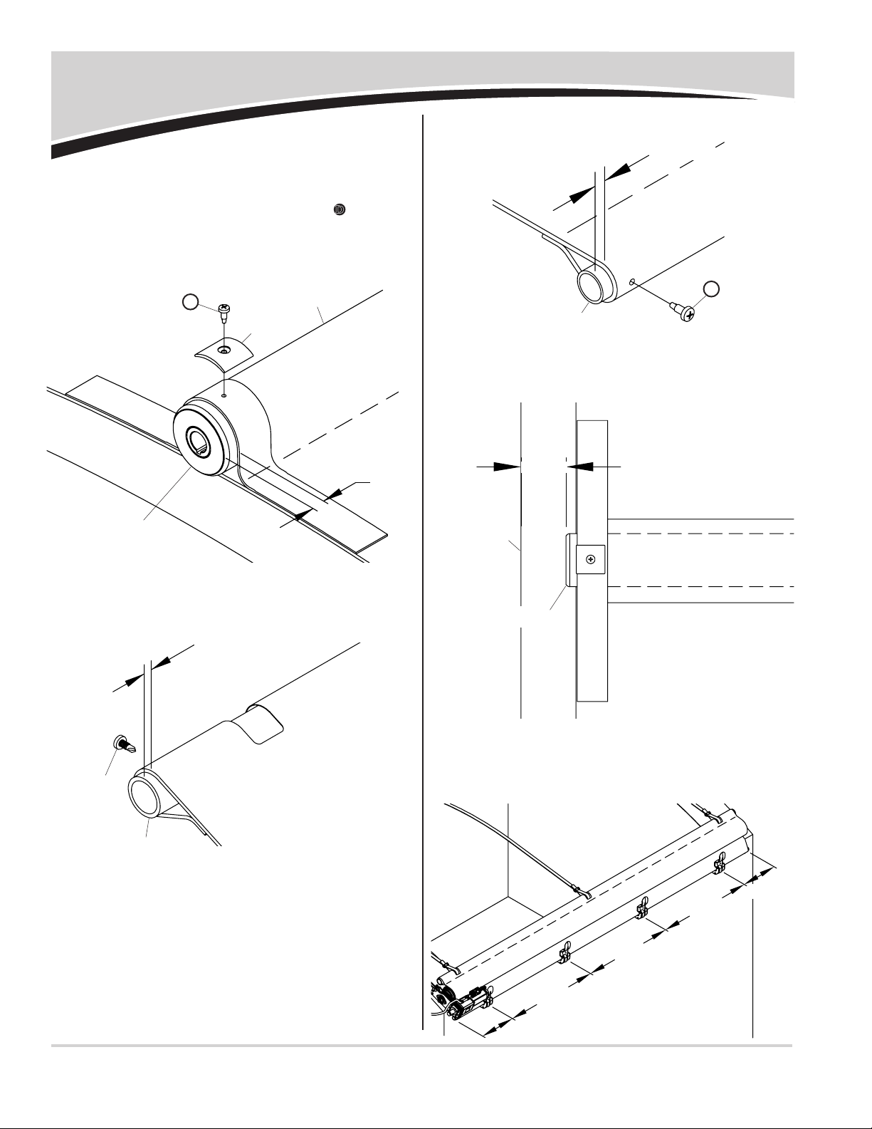
STEP 11: Secure xing bar to box using preferred method. If
using sheet stops, mount rst and last sheet stops
320mm from edge of sheet. Equally space remaining
sheet stops.
STEP 7: Insert center pole into center pole pocket on sheet.
Align hole in center pole with hole in sheet and secure
sheet to pole with U-clamp and screw D. Pull sheet
tight and repeat on other end of pole. Install third U-
clamp and screw at center of center pole.
STEP 8: Fasten pull bar to sheet with self-drilling screw. Align
hole in sheet with hole in bar and secure. Pull sheet
tight and repeat on other end.
STEP 9: Repeat step 7 for xing bar.
STEP 10: Place sheet on top of box with xing bar hanging over
right side of box. Move sheet forward or backward
until center pole insert plug is 75mm from front face
of hood.
75mm
self-
drilling
screw
sheet
pull bar
fixing bar
sheet
sheet
front of
hood
center pole
16mm
u-clamp
center pole
center pole
pocket
9.5mm
9.5mm
D
D
320mm
320mm
evenly space
evenly space
evenly space
UK HELP LINE: +44 (0) 1795 473499
P/N 1127925
4
Center Pole Drive Motor
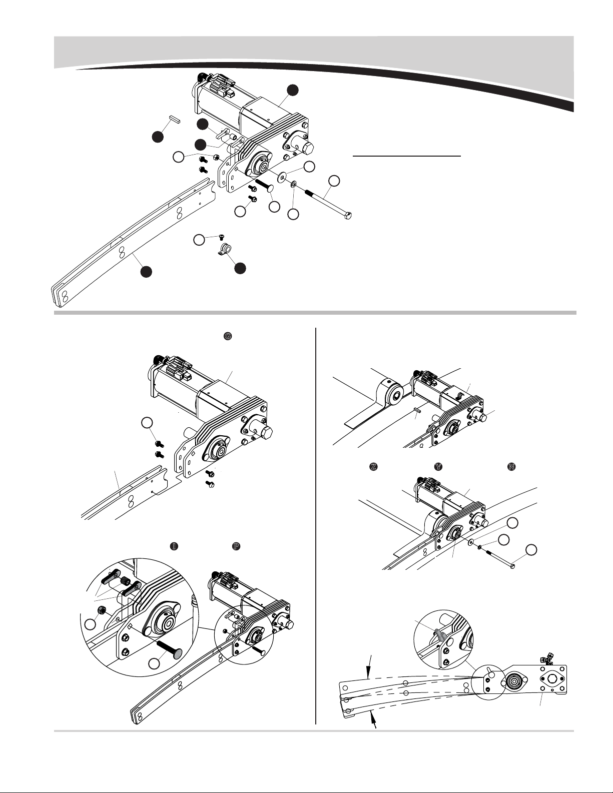
STEP 3: Install center pole drive motor. Insert key stock into
center pole plug keyway. Align keyway on drive shaft
by turning manual override shaft clockwise or coun-
terclockwise and insert shaft into center pole plug.
motor
key
motor
center pole
rotate to align
manual override
shaft to keyway
1
10
Item Part # Description
1. 1124987 Center Pole Pivot Arm Assembly - High Rise
1124981 Center Pole Pivot Arm Assembly - Low Rise
2. 1124968 Center Pole Drive w/Motor
1124978 Center Pole Drive w/Motor - Reverse Roll
3. 1705344 Wire Clip - 1/2"
4. 1124985 Center Pole Cam
5. 1124982 Bushing - 1/2" x .334" x 1/2"
6. 1123996 Key Stock - 1 1/4"
B. 1705353 Machine Screw - M6 x 10
G. 1705551 Flanged Cap Screw - M6 x 16
I. 1705550 Carriage Bolt - M8 x 1.25 x .50
N. 1705355 Cap Screw - M10 x 1.5 x 150
P. 1705349 Nylon Lock Nut - M8 x 1.25
Y. 1705350 Lock Washer - M10
Z. 1705347 Fender Washer - 10.5mm x 30mm
2
5
6
STEP 1: Align holes in pivot arm with holes in center pole drive
and fasten loosely with screws G.
STEP 2: Loosely fasten bushing and cams to center pole drive
with carriage bolt I and lock nut P.
center pole drive
pivot arm
cams &
bushing
3
STEP 5: To adjust pivot arm and drive/motor assembly to be
in contact with hood, rotate cams upward until tight.
Tighten all fasteners securely.
adjust pivot arm
drive/motor
assembly
rotate cams upward
N
Z
Y
I
G
B
P
G
I
P
N
Z
Y
STEP 4: Secure drive motor to center pole with fender washer
Z, lock washer Yand cap screw N. Torque bolt to
54 Nm.
UK HELP LINE: +44 (0) 1795 473499
P/N 1127925
STEP 1:
Remove motor assembly from spool bracket pre-
assembly by removing four 5/16" anged lock nuts.
5
Web Spool & Drive Motor
Item Part # Description
1. 1124434 Spool Bracket - 5.25" UK
1124805 Spool Bracket - 5.25" UK - RR
2. 1705381 Spool Web Guide
3. 1123999 Spool Assembly - 5.25" - UK
4. 1120679 Motor Spacer
5. 1705252 Spool Motor - UK
1705453 Spool Motor - UK - RR
6. 1705460 Spool Roller - UK
7. 1124436 Spool Cover - 5.25" - UK
8. 1124043 Bushing Spacer - 1 3/16"
9. 1805587 Webbing - 6m x 25mm - Front
10. 1805588 Webbing - 12m x 25mm - Rear Ridged
11. 1805589 Webbing - 18m x 25mm - Rear - Trailer
12. 1705581 ShurCover Decal
C. 1705371 Flanged Cap Screw - M5 x 12
F. 1705378 Self-Tapping Screw - 5/16" x 3/4"
J. 1700400 Self-Tapping Screw - 3/8" x 1"
M. 1705370 Cap Screw - M10 x 60
O. 1705461 Cap Screw - M12 x 130
Q. 1704931 Flanged Lock Nut - 5/16"
S. 1700407 Hex Nut - 3/8"
U. 1705361 Lock Nut - M10
V. 1705373 Lock Nut - M12
W. 1700434 Lock Washer - 3/8"
1
4
5
2
6
7
8
NOTE: Steps
1 and 2 are for
pre-assembled
spool brackets
only. All others
start at step 3.
STEP 2: Remove web spool and plastic washer from spool
bracket pre-assembly by removing four screws F.
motor
shaft
spool bracket
spool bracket
plastic washer
web spool
skip to step 5 if using preassembled spool bracket
911
10
web spool
flanged
lock nut
F
S
W
OF
C
J
M
U
V
C
3
Q
12

UK HELP LINE: +44 (0) 1795 473499
P/N 1127925
6
Web Spool & Drive Motor - continued
STEP 5C: Mark and drill 8mm holes in (minimum) 4 locations.
8mm holes
STEP 5B: Position top of bracket approximately 300mm below
installed pull bar when in closed position.
STEP 5A: Align edge of bracket ush with side of trailer or edge
of mounting bracket.
300mm
edge of
bracket
edge of
trailer
spool bracket
pull bar
STEP 4: Fasten spool web guide to spool bracket with six
screws C.
spool
bracket
spool web guide
STEP 3: Fasten spool roller to spool bracket with M12 cap
screw O and lock nut V.
spool
bracket
spool
roller
STEP 5: Determine location for spool bracket on front of box.
NOTE: Custom bracket may be required for boxes with
radius and diagonal corners.
O
V
C

UK HELP LINE: +44 (0) 1795 473499
P/N 1127925
7
STEP 7: Insert motor shaft through plastic washer and hole
in spool bracket. Secure with four 5/16" anged lock
nuts Q.
Web Spool & Drive Motor - continued
web spool
motor
shaft
spool
bracket
STEP 6: Install web spool and plastic washer into spool bracket.
Secure with impact wrench and screws F.
spool bracket
plastic washer
web spool
top view
spool
bracket
NOTE: Use lock washers and nuts if possible. Minimum wall
thickness of 4.75mm is required when using self-tapping
screws Jwithout lock washers Wand nuts S.
STEP 5D: Secure spool bracket to trailer with impact wrench
and four self-tapping screws J.
spool bracket
F
Q
J
J
W
S
UK HELP LINE: +44 (0) 1795 473499
P/N 1127925
8
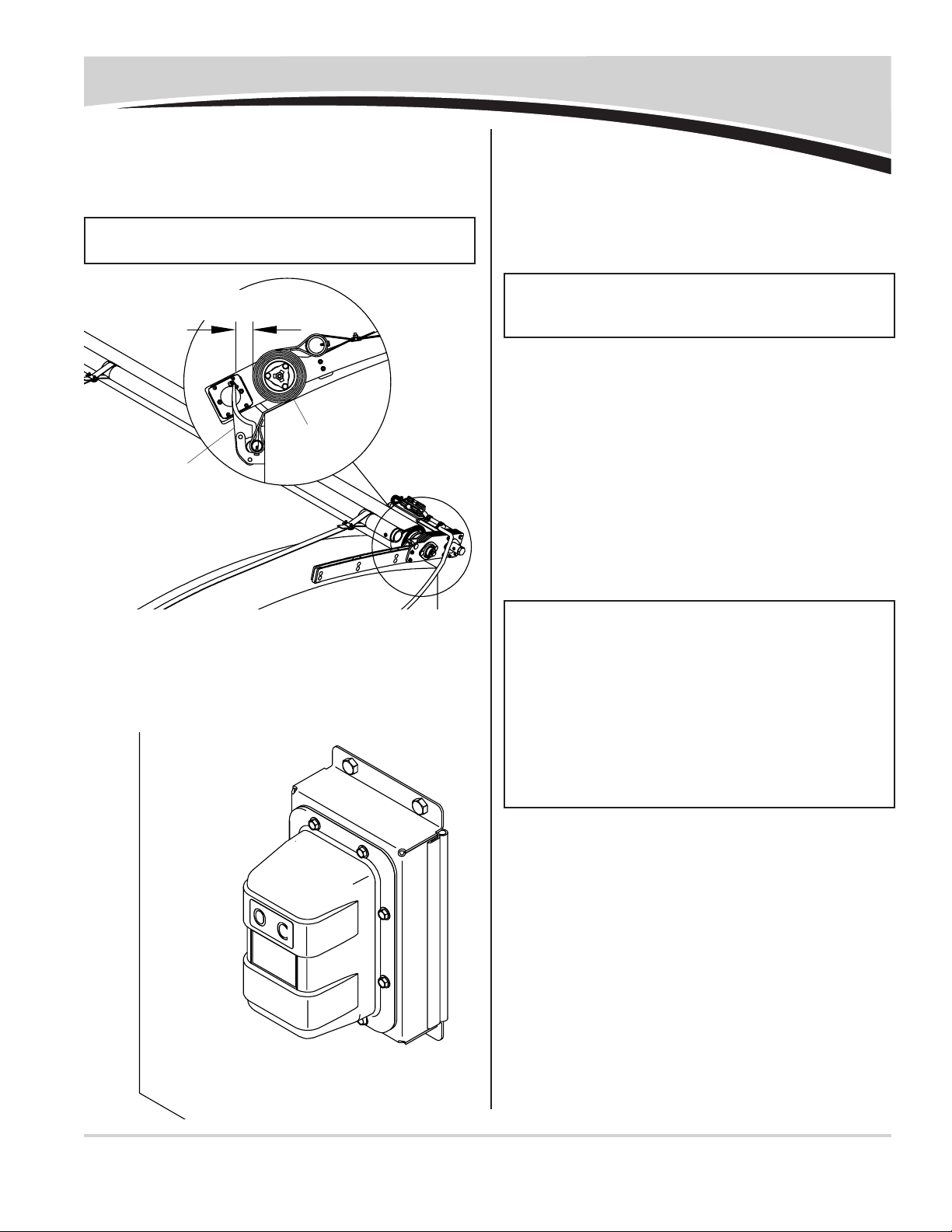
STEP 11: Rotate web spool until yellow screw M can be installed
into holes on bottom of spool. Install screw and secure
with nut U.
Web Spool & Drive Motor - continued
STEP 10: Push webbing and spacers back into spool and secure
with M8 x 120 cap screw and lock washer. Tighten
screws.
STEP 9: Route webbing through spool bracket web guide and
insert bushing spacers into loops.
spool
bracket
web guide
insert bush-
ing spacers
into loops
webbing
STEP 8: Rotate web spool so M8 x 120 screw is facing forward.
Remove screw and loosen other two screws so two
bushing spacers can be removed.
web spool
remove
bushing
spacers
m8 x120
cap screw
M
U
m8 x120
cap screw

UK HELP LINE: +44 (0) 1795 473499
P/N 1127925
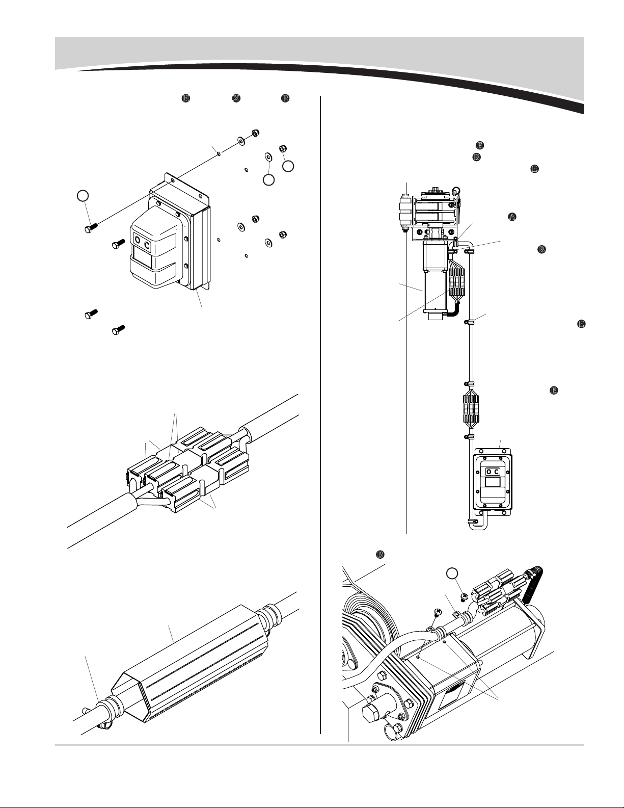
9
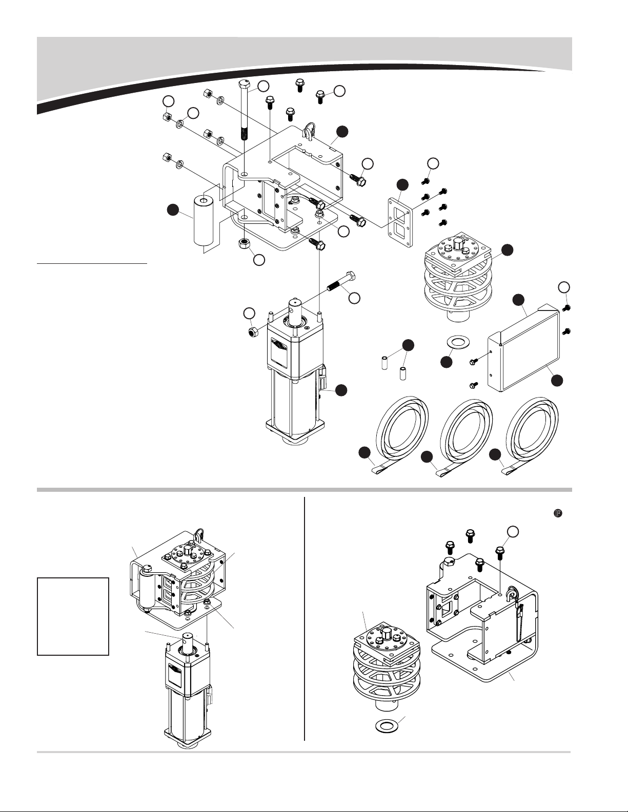
SMART1+™ Wireless Receiver
Follow these steps if wiring wireless receiver onto front skin of
trailer. Skip to step 10 if wiring behind skin of trailer.
STEP 1: Determine mounting location for wireless receiver
bracket. Bracket has manual switch and should be
located where easily accessible and safe to operate
sheet, (typically on driver side of front skin, where it
can be reached without climbing on trailer).
Verify wire lengths before drilling holes. Dual-con-
ductor red (+) and black (-) wire must reach 24V DC
power supply. Two marked 3-conductor wires must
reach junction boxes on spool motor or center pole
drive motor. Observe full motion of center pole motor
and supply enough wire for motor to reach fully open
and closed sheet positions.
STEP 2: Using holes on receiver as guide, mark and drill four
5mm holes.
manual
switch
wireless
receiver
driver side
of front skin
holes in
receiver
Item Part # Description
1. 1125035 Velcro® Cable Cover
2. 1126867 SMART3™ Remote
3. 1125047 Jumper Wire - Spool - Standard
1125048 Jumper Wire - Arm - Standard
1125049 Jumper Wire - Spool - Reverse Roll
1125050 Jumper Wire - Arm - Reverse Roll
4. 1127919 SMART3™ Wireless Receiver
5. 1705808 Wire Clip - 5/8"
6. 1705376 Wire Clip - 1/2"
7. 1120817 Female SMARTwire™ - 13.3 mm²- 1.9m
1704994 Female SMARTwire™ - 13.3 mm²- 12m
1704988 Female SMARTwire™ - 13.3 mm²- 19.8m
1704989 Female SMARTwire™ - 21.2mm²- 27.4m
1125396 Female SMARTwire™ - 21.2mm²- 30m
8. 1704757 Harness Lock Pin
9. 1701595 End Plug - 1"
A. 1705376 Flanged Cap Screw - M5 x 16
B. 1705353 Machine Screw - Pan Hd. - M6 x 10
E. 1704338 Self-Tapping Screw - 1/4" x 1"
H. 1702926 Cap Screw - 5/16" x 7/8"
R. 1700419 Nylon Lock Nut - 5/16"
X. 1700428 Flat Washer - 5/16"
5
4
2
3
1
H
E
XR
8
7
9
6
A
B
gear
box
spool
bracket
wire
runs
UK HELP LINE: +44 (0) 1795 473499
P/N 1127925
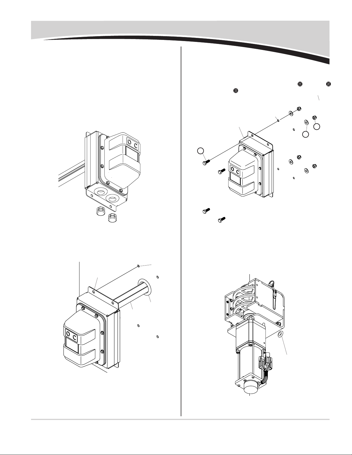
10
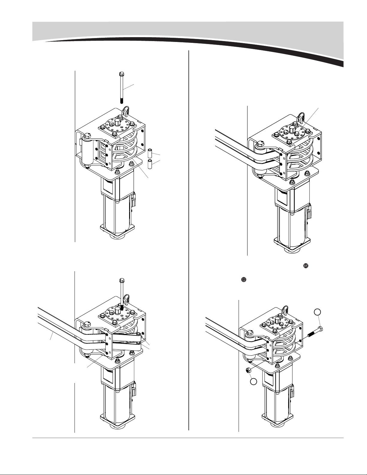
SMART1+™ Wireless Receiver - continued
STEP 4: Connect jumper wire between wireless receiver wire
mandel spool and wire connected to spool motor.
Connect wire ends to matching colored wire ends.
STEP 3: Align holes on wireless receiver with holes on trailer.
Fasten with screws H, washers X and nuts R.
STEP 6: Route connected wires from spool motor to wireless
receiver. Secure wire to bottom of spool bracket with
5/8" wire clip and screw E. Secure to gear box with
1/2" wire clip and screw B. Secure wire to trailer with
5/8" wire clips and self-drilling screws E.
hole in
trailer
spool motor
wireless receiver
wireless receiver
white
black
green
secure 3-conductor
jumper wire w/5/8"
wire clips & screws E
velcro®
cable wrap
not shown
STEP 5: Cut Velcro® cable wrap into six 6" pieces. Wrap around
wire connections. Secure wire with wire clips.
wire clip w/
self-drilling
screw
velcro®
cable wrap
STEP 6A:
Secure wire to motor with 1/2" wire clips and screws
B
,
fastening through existing holes in motor assembly.
wire clip
holes in motor
X
R
H
B
secure wire to
trailer w/5/8"
wire clips &
screws E
secure w/1/2"
wire clips &
screws A
secure w/1/2"
wire clips &
screws B

UK HELP LINE: +44 (0) 1795 473499
P/N 1127925
11
SMART1+™ Wireless Receiver - continued
CAUTION
From this point, spool, sheet and webbing
may move and become tight.
!
STEP 8: Route dual-conductor red (+) and black (-) wires to
24V power supply and connect in best way. Secure
wire with wire clips and self-drilling screws.
NOTE: For tipping trailers, route female SMARTwire™ on
box to trailer pivot, then back to 24V power supply on trailer
frame. Add circuit breaker if 24V power supply is not already
protected with one. Align breaker with red (+) lead, placing
as close as possible to power source.
SKIP TO SYSTEM SETUP.
STEP 9: Determine mounting location for wireless receiver.
NOTE: Receiver has manual switch. Locate where easily
accessible and safe to operate sheet, typically on driver side
of front skin where it can be reached without climbing on
trailer.
to 24v
power
supply
wire clips
& screws
STEP 7: Repeat steps 4 through 5 for center pole drive motor.
center pole drive motor
wireless receiver
spool drive/
motor assembly
jumper wire
STEP 10: Using holes on receiver
as guide, mark and
drill four 5mm holes as
shown.
STEP 11: Measure as
shown from
top left 5mm
hole. Mark
and drill
51mm hole.
28mm
64mm
drill
51mm
hole
5mm hole
lock pin
UK HELP LINE: +44 (0) 1795 473499
P/N 1127925
12
STEP 14: Align holes on wireless receiver with holes on trailer.
Fasten receiver to trailer with screws H, washers X
and nuts R.
STEP 13: Install 1 1/2" rubber grommet into 81mm hole. Pass
three wires through rubber grommet and align holes
in bracket with drilled holes. STEP 15: Drill hole in location shown and install rubber grommet
with 14mm ID (grommet not supplied).
SMART1+™ Wireless Receiver - continued
rubber
grommet
three
wires
hole in
bracket
drilled
hole
hole in trailer
wireless receiver
grommet
STEP 12: Pull all three wires out of rubber grommets on bottom
of receiver bracket. Insert two 1" plugs into rubber
grommets.
Verify wire lengths before drilling holes. Dual-con-
ductor red (+) and black (-) wire must reach 24V DC
power supply. Two marked 3-conductor wires must
reach junction boxes on spool motor or center pole
drive motor. Observe full motion of center pole motor
and supply enough wire for motor to reach fully open
and closed sheet positions.
H
X
R
UK HELP LINE: +44 (0) 1795 473499
P/N 1127925
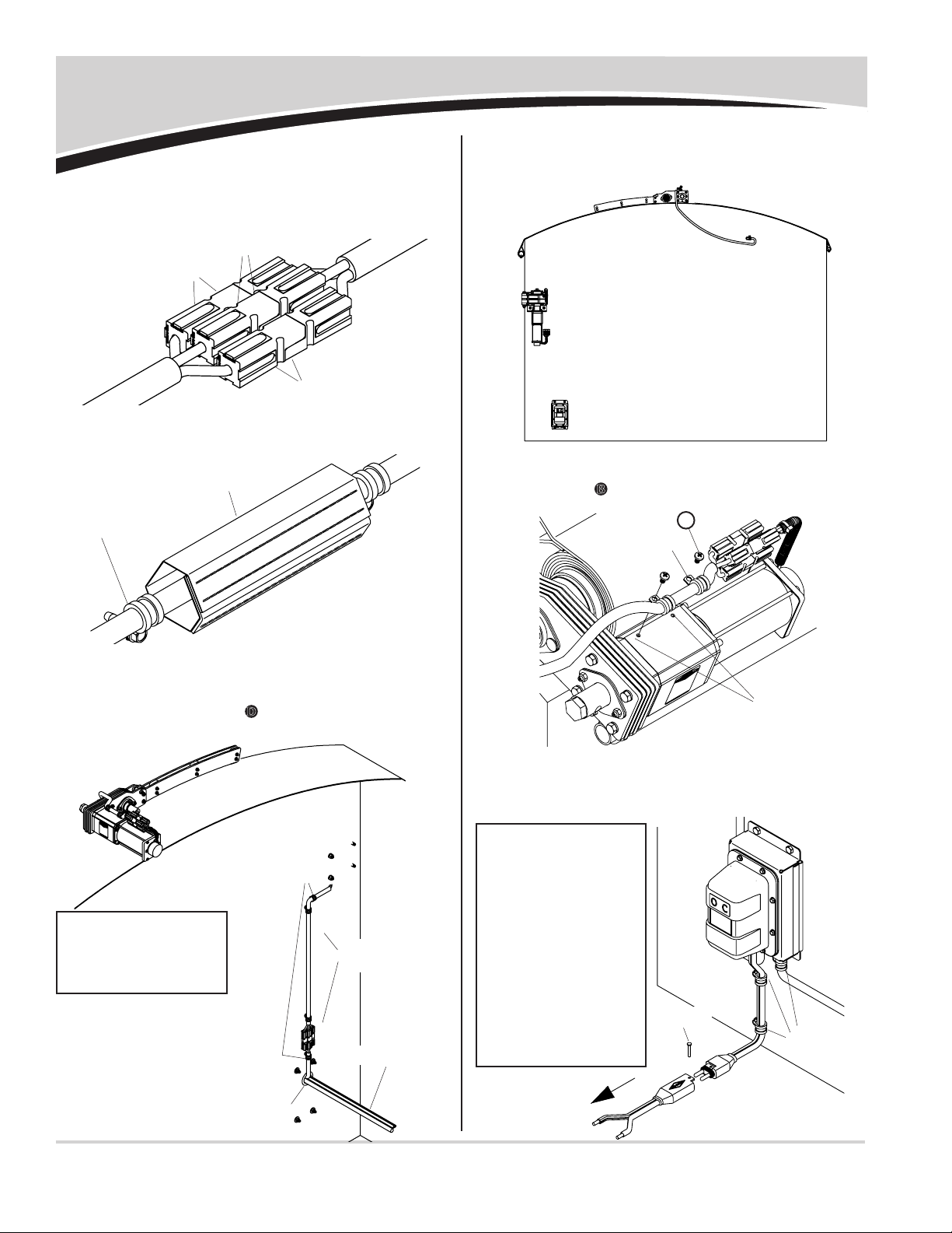
13
SMART1+™ Wireless Receiver - continued
STEP 18: Route 3-conductor wire marked for spool motor
through rubber grommet and to junction box on spool
motor. Secure wire to bottom of spool bracket with
wire clip and screw D. Secure wire to trailer with wire
clips and self-drilling screws.
NOTE: Use care to
prevent damage to front
skin while securing wire
clips and drilling holes.
3-strand wire
inside of
trailer shown
grommet
wire clips
& screws
NOTE: For tipping
trailers, route female
SMARTwire™ on box to
trailer pivot, then back
to 24V power supply on
trailer frame. Add circuit
breaker if 24V power
supply is not already
protected with one. Align
breaker with red (+)
lead, placing as close
as possible to power
source.
to 24v power
supply
wire clips
& screws
STEP 16: Connect jumper wire between wireless receiver wire
mandel spool and wire conncected to spool motor.
Connect wire ends to matching colored wire ends.
white
black
green
STEP 17: Cut Velcro® cable wrap into six 6" pieces. Wrap around
wire connections. Secure wire with wire clips.
wire clip w/
self-drilling
screw
velcro®
cable wrap
velcro®cable
wrap not shown
STEP 19A:
Secure wire to motor gear with 1/2" wire clips and
screws B, fastening through existing holes in motor.
wire clip
holes in motor
STEP 20: Route dual-conductor red (+) and black (-) wires to
24V power supply and connect in best way. Secure
wire with wire-clips and self-drilling screws.
STEP 19: Repeat steps 15 to 16 for center pole drive motor,
securing wire to box with wire clips and M6 screws.
lock pin
B
UK HELP LINE: +44 (0) 1795 473499
P/N 1127925
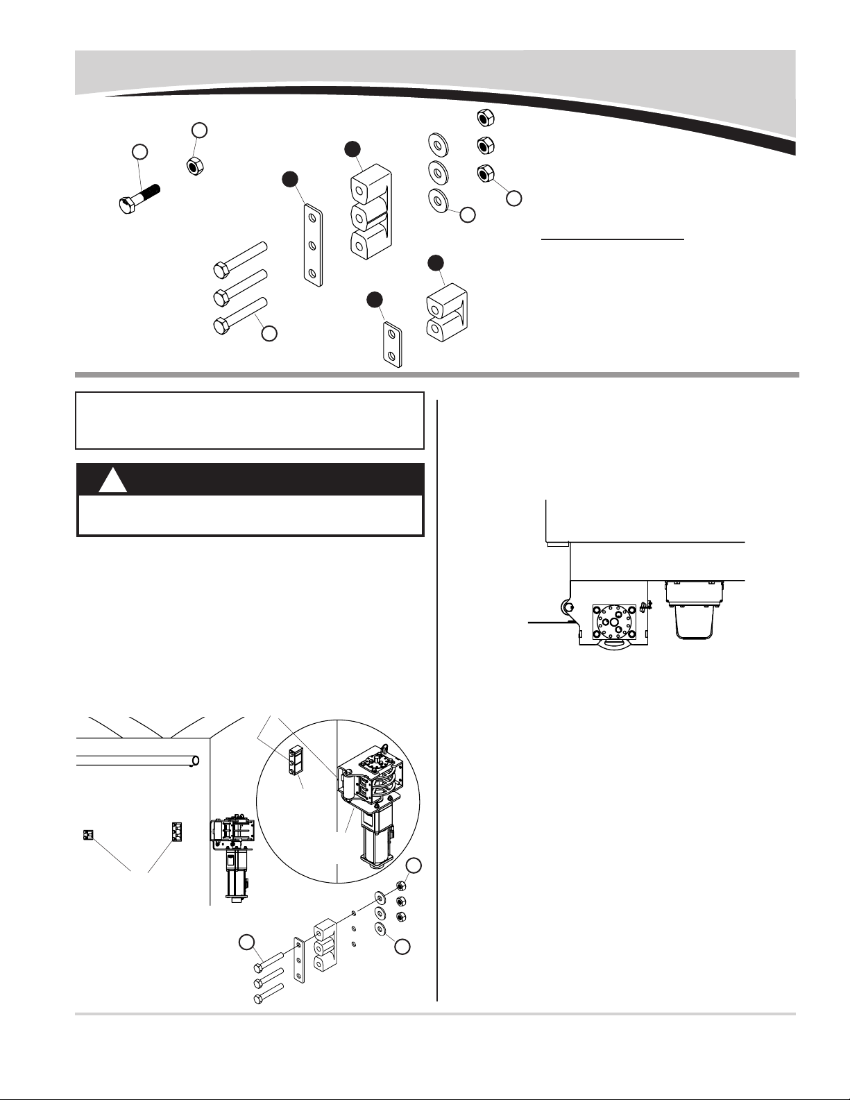
14
System Setup
STEP 3: Press and hold Open button on wireless receiver
to release motor breaks. Pull webbing out of spool
bracket until webbing has been unwound from spool.
Bolt marked with red end will be in this location. Two
people may be required to safely complete this step.
red mark
NOTE: Add circuit breaker if 24V power supply is not
already protected with circuit breaker. Align breaker with red
(+) lead and place as close to power source as possible.
CAUTION
From this point, spool, sheet and webbing
may move and become tight.
!
STEP 1: Unplug white quick-disconnects for motor wire from
white control box wire, for spool and center pole
motors. This will allow motor breaks to be energized
(released) without running motors.
STEP 2:
Install web guide blocks on side of box. Install at correct
height in reference to spool to extend life of webbing. Dur-
ing operation, webbing should be centered in openings
when entering spool bracket.
web
guide
block
web guide blocks
align center hole in web guide
w/notch in spool bracket
spool
bracket
fasten web
guide to
trailer as
shown
Item Part # Description
1. 1705554 Webbing Strap Guide - Large
2. 1705553 Webbing Strap Guide - Small
3. 1124992 Webbing Strap Guide Plate - Large
4. 1124989 Webbing Strap Guide Plate - Small
K. 1705357 Cap Screw - M10 x 45 - GD10
L. 1705556 Cap Screw - M10 x 65
T. 1705555 Nylon Lock Nut - M10
U. 1705361 Nylon Lock Nut - M10 - GD10.9
a. 1701176 Flat Washer - 3/8"
1
3
4
2
K
U
L
a
T
La
T
UK HELP LINE: +44 (0) 1795 473499
P/N 1127925
15
System Setup - continued
STEP 7: Thread webbing through guides and secure webbing
to pull tube. Do not cut webbing to length at this time.
Connection may need to be adjusted but should be
secured to take full torque of motor.
webbing
web guide
blocks
these two web guides maybe be
positioned higher on trailer to
reduce wind whip during travel
STEP 8: Reconnect white quick-disconnect for center pole
motor. Quickly press and release Open button on
wireless receiver until hole in center pole motor is
lined up with hole in drive sprocket. Insert M10 x 45
cap screw K and secure with M10 nylon lock nut U.
STEP 6: Reconnect white quick-disconnect for spool motor
wire. Press and hold close button. Allow webbing to
roll up on spool until 2430mm mark reaches bracket.
Two people may be needed to safely complete this
step.
STEP 4:
Stretch webbing and mark 2540mm from spool bracket.
STEP 5: Fasten spool bracket
cover to spool brack-
et with four M5 x 12
anged screws.
WARNING
Use extreme caution working by spool. Keep
hands and fingers clear of all moving parts
and pinch points.
!
2540.0mm
webbing
spool bracket
SECURE WEBBING TO PULL TUBE
step 1 step 2 step 3 step 4
K
U
UK HELP LINE: +44 (0) 1795 473499
P/N 1127925
16
System Setup - continued
STEP 11: With sheet still in fully open position, release webbing
clamps (not supplied) and remove all slack from web-
bing and sheet. Re-secure webbing.
STEP 12: Connect any quick-disconnects that were discon-
nected in previous steps. Open and close sheet using
Open and Close buttons and review operation.
NOTE: During operation, webbing and spool will unwind
until all of webbing is unwound and will act as stop. This will
be fully open location of sheet.
STEP 13: If adjustments are needed, close sheet, disconnect
center pole motor wire from white control wire and
press and hold Open button. Pull some webbing from
spool and release button. Release webbing clamps
and make necessary adjustments. Re-secure clamps.
STEP 14: Connect quick-disconnects and verify operation.
STEP 10: Unplug white quick-disconnect for motor wire on cen-
ter pole motor. Press and hold Open button, this will
release motor breaks. Unwind any remaining webbing
from spool until marked bolt is in far left location. Two
people may be needed to safely complete this step.
STEP 9: Press and hold Open button until center pole reaches
fully open position, just short of reaching sheet stops.
This will protect sheet from damage from rubbing
against stops.
NOTE:
Stop center pole early if you would prefer to prevent
center pole arm assembly from hanging past side of box.
roll-over
bracket
center pole
stop center pole short
of roll-over bracket
NOTE: As a nal check, run sheet open and closed in
Express Mode. System should stall when fully open
and fully closed. One second after stalling, SMART3™
electronics will disconnect power to motors. You can check
this by stalling motor in open and closed positions and listen
carefully for solenoid under black wireless receiver cover to
click after one second of stall.
SMART3™ Operator’s Instruction Guide and ShurCover™
Operating Instructions are available on our web site:
http://www.shurco.co.uk.

UK HELP LINE: +44 (0) 1795 473499
P/N 1127925
Replacement Parts
17
SHEET COMPONENTS
Item Part # Description
1. 1123980 Center Pole Plug - UK
2. 1700398 Self-Drilling Screw - 1/4" x 3/4"
3. 1701354 U-Clamp
4. ______ Center Pole
5. ______ Pulling Bar
6. ______ Fixing Bar
7. ______ Sheet (not shown)
2
1
3
4
6
5
SYSTEM SETUPS
Item Part # Description
1125374 Webbing Guide Kit - Single
(Includes 2, 4, 2 of 5, 6 & 7)
1125375 Webbing Guide Kit - Double
(Includes 1, 3, 3 of 5, 6 & 7)
1. 1705554 Webbing Strap Guide - Large
2. 1705553 Webbing Strap Guide - Small
3. 1124992 Webbing Strap Guide Plate - Large
4. 1124989 Webbing Strap Guide Plate - Small
5. 1705556 Cap Screw - M10 x 65
6. 1705565 Nylon Lock Nut - M10
7. 1701176 Flat Washer - 3/8"
8. 1805587 Front Strap - 6m
9. 1805588 Rear Strap - 12m
10. 1805589 Rear Strap - 18m
1
3
4
2
6
7
5
8910
Table of contents
Other Shurco Automobile Accessories manuals


Popular Automobile Accessories manuals by other brands


Hoffmann
Hoffmann monty 2300 Operation manual

DEFA
DEFA eConnect user manual

DEFA
DEFA 411102 Fitting instructions

Whispbar
Whispbar K693W Fitting instructions

AEM Performance Electronics
AEM Performance Electronics 2001-2005 Honda K Series instruction manual

Renault
Renault 77 11 423 432 installation instructions


