CruizCore XG1350 User manual

User Manual Rev1.1
CruizCore®XG1350
Digital Gyroscope
2013. 05. 20
CopyrightMicroinfinity Co., Ltd.
http://www.minfinity.com
Contact Info.
EMAIL: support@minfinity.com, TEL: +82 31 546 7426 FAX: +82 31 546 7409

CruizCore®XG1350 USER MANUAL
Microinfinity reserves all rights in this document and its subject matter. The recipient acknowledges these rights and assures the use of this document only for the purpose it was delivered.
ii
BLANK
PAGE

CruizCore®XG1350 USER MANUAL
Microinfinity reserves all rights in this document and its subject matter. The recipient acknowledges these rights and assures the use of this document only for the purpose it was delivered.
iii
Contents
1. Introduction.............................................................................................................................1
2. Hardware Description.............................................................................................................3
2.1. System Description...........................................................................................................3
2.2. Part List Included with this Kit...........................................................................................3
2.3. Cable Pin-out....................................................................................................................4
2.3.1. USB Cable...................................................................................................................4
2.4. Mounting Information (Coordinate System)......................................................................4
2.5. Sensor Start-up.................................................................................................................5
3. Software Description..............................................................................................................6
3.1. Output Data Format..........................................................................................................6
3.2. Monitoring Program..........................................................................................................6
3.2.1. Installation ...................................................................................................................6
3.2.2. Main Window...............................................................................................................7
3.2.3. Rate Window...............................................................................................................7
3.2.4. Angle Window..............................................................................................................7
3.2.5. Acceleration Window...................................................................................................7
3.2.6. Compass Window........................................................................................................8
3.2.7. Data Window...............................................................................................................8
3.2.8. Icon Toolbar.................................................................................................................8
4. System Characteristics ........................................................................................................10
4.1. Physical Characteristics .................................................................................................10
4.2. Environmental Characteristics........................................................................................11
4.3. Electrical Characteristics ................................................................................................12
4.4. Performance Characteristics..........................................................................................13

CruizCore®XG1350 USER MANUAL
Microinfinity reserves all rights in this document and its subject matter. The recipient acknowledges these rights and assures the use of this document only for the purpose it was delivered.
iv
List of Figures
Figure 1: CruizCore®XG1350.......................................................................................................1
Figure 2: CruizCore®XG1350 part list. .........................................................................................3
Figure 3: Type A USB connector. ..................................................................................................4
Figure 4: CruizCore®XG1350 coordinates system.......................................................................5
Figure 5: Program main window....................................................................................................6
Figure 6: Rate window...................................................................................................................7
Figure 7: Angle window. ................................................................................................................7
Figure 8: Data window...................................................................................................................8
List of Tables
Table 1: CruizCore®XG1350 part list description..........................................................................3
Table 2: USB connector type Apin-out..........................................................................................4
Table 3: CruizCore®XG1350 physical characteristics. ...............................................................10
Table 4: CruizCore®XG1350 environmental characteristics.......................................................11
Table 5: Judgment criteria of environment and mechanical test.................................................11
Table 6: CruizCore®XG1350 electrical characteristics. ..............................................................12
Table 7: CruizCore®XG1350 performance characteristics.........................................................13

CruizCore®XG1350 USER MANUAL
Microinfinity reserves all rights in this document and its subject matter. The recipient acknowledges these rights and assures the use of this document only for the purpose it was delivered.
v
BLANK
PAGE

CruizCore®XG1350 USER MANUAL
Microinfinity reserves all rights in this document and its subject matter. The recipient acknowledges these rights and assures the use of this document only for the purpose it was delivered.
1
1. Introduction
The CruizCore®XG1350 is a fully self-contained MEMS digital gyroscope and accelerometer
based on the CruizCore® R1 Series platform. Compared with the R1 Series, the XG1350 was
designed with convenient packaging and communication interfaces to allow its use as a
standalone sensor(see Figure 1). It provide USB, the output and baud rate are adjustable for
the customers’ convenience. The XG1350 includes a MEMS gyroscope, 3axis accelerometer,
internal voltage regulation, data acquisition and signal processing circuitry, communication
interfaces and a RISC microprocessor running our patented error correcting algorithm. Because
it uses MEMS sensors, it has the advantage of being light weight, small size and consuming low
power. The XG1350 is packaged in a hard case for increasing protection against external
impact. The XG1350 uses an adaptive reduced order Kalman filter to stabilized angular rates
and heading angles, virtually eliminating the most common errors (i.e. bias drift, scale factor,
temperature effects). The XG1350 has a 50Hz bandwidth and can precisely measure angular
rates up to ± 100 deg/sec, it can also measure rates up to ± 150 deg/sec with lesser accuracy.
The start-up time is less than one second, which is used to compute bias parameters; it does
not require further calibration thereafter. The XG1350 is the best single axis rate measuring
solution for navigation applications.
The CruizCore®XG1350 has the following features:
Ultra low bias drift
High resolution and accuracy
Outstanding scale factor linearity
Fast start-up
Fully self-contained
Digital output (USB)
Low power consumption
Low cost
Roughed and compact package
User friendly monitoring and testing program
Figure 1: CruizCore®XG1350.

CruizCore®XG1350 USER MANUAL
Microinfinity reserves all rights in this document and its subject matter. The recipient acknowledges these rights and assures the use of this document only for the purpose it was delivered.
2
NOTICE: We recommend extensive testing of this product before using it in a final
application. Specifically, this product should be tested in the same environmental
conditions that it is intended to be used. Furthermore, we strongly recommend caution
when using our product in sensitive applications that can cause injures, death or
property damage due to the wrong operation of this product, which may be caused by
unexpected environmental changes such as temperature, shock, excessive and
continuous vibration, etc. These applications include but are not limited to:
Aircraft equipment
Air vehicles
Aerospace equipment
Underwater vehicles
Medical equipment
Transportation equipment
Disaster prevention/crime prevention equipment
Applications which require especially high reliability and accuracy
Disclaimer and Limitation of Liability for Damages.
Microinfinity shall not be liable, under any circumstances, for any special, indirect, incidental,
consequential, or contingent damages for any reason, whether or not the buyer has been
advised of the possibility of such damages.
CruizCore®XG1350 USER MANUAL
Microinfinity reserves all rights in this document and its subject matter. The recipient acknowledges these rights and assures the use of this document only for the purpose it was delivered.
3
2. Hardware Description
2.1. System Description
The CruizCore®XG1350 is compact, light, low-power consuming digital gyroscope and
accelerometer. It uses a MEMS rate and acceleration sensor. It has internal power regulation to
minimize the power noises. The input voltage range of 4.75 V to 5.25 V is acceptable for power
supply.
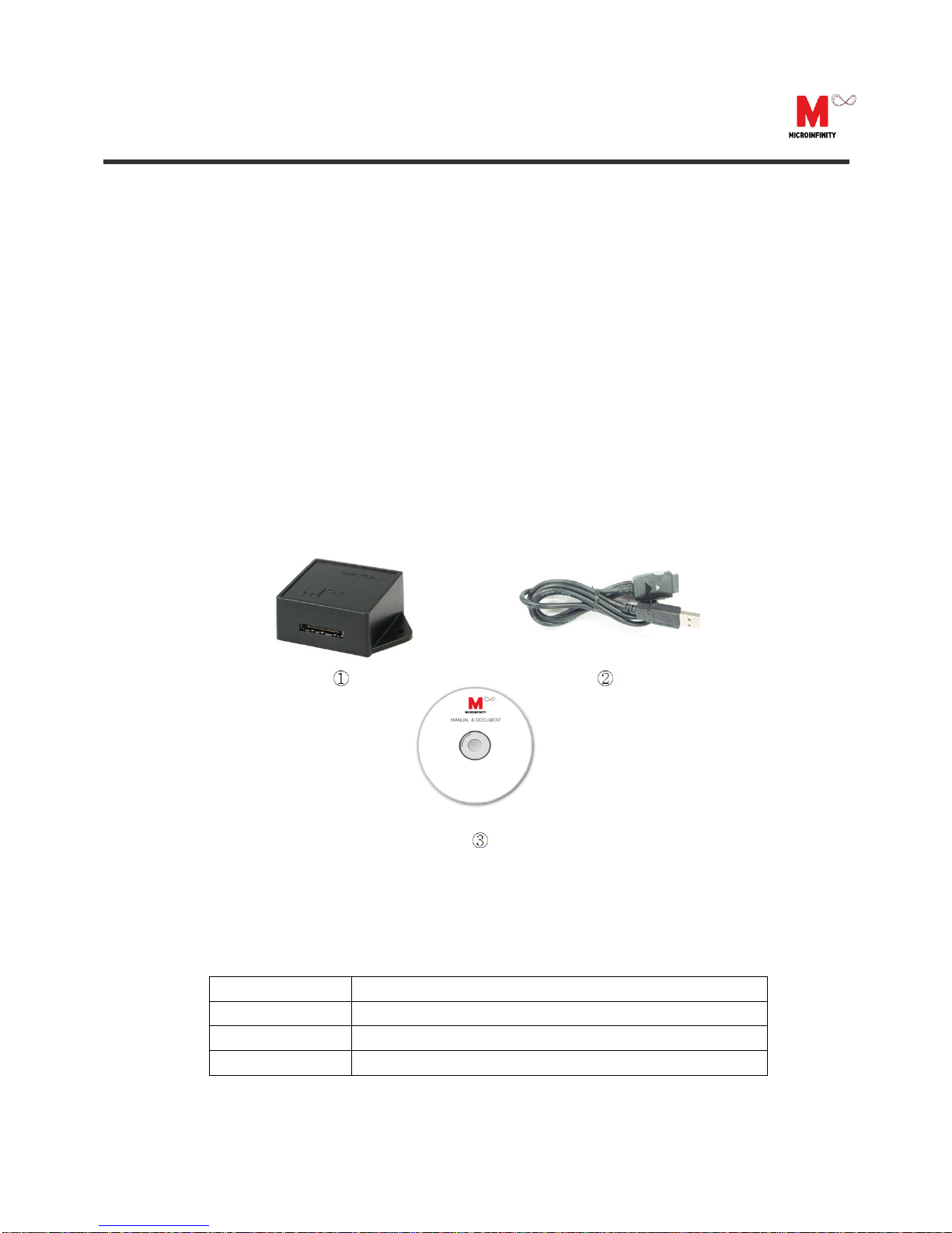
2.2. Part List Included with this Kit
The CruizCore®XG1350 is a full developer’s kit intended to facilitate testing and understanding
the CruizCore® R1 Series. Therefore it includes all the necessary cables and software needed
for that purpose. The list of materials included with this kit is shown in Figure 2 and described
in Table 1:
Figure 2: CruizCore®XG1350 part list.
Table 1: CruizCore®XG1350 part list description.
Item Number
Description
1
CruizCore®XG1350
2
USB cable
3
CD-ROM (includes User Manual and sensor testing program)

CruizCore®XG1350 USER MANUAL
Microinfinity reserves all rights in this document and its subject matter. The recipient acknowledges these rights and assures the use of this document only for the purpose it was delivered.
4
2.3. Cable Pin-out
For convenience, the CruizCore®XG1350 can communicate with external devices using two
different interfaces: USB cable.
2.3.1. USB Cable
The CruizCore®XG1350 USB connection is of type A (see Figure 3), the pin-out description is
presented in Table 2.
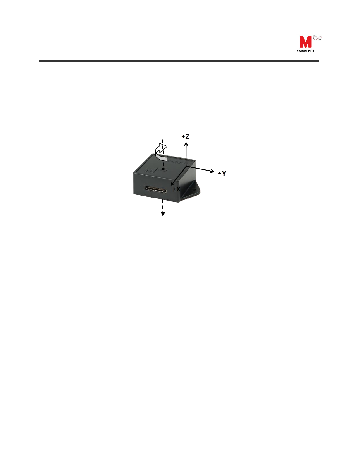
2.4. Mounting Information (Coordinate System)
The CruizCore®XG1350 coordinate system has its sensitive axis perpendicular to the device
flatter area (see Figure 4), therefore the gyro will show a positive angular rate (and angle
increment) when its sensitive axis is rotated in the clock-wise direction (other coordinate
systems are available as an option). Incorrect mounting can produce misalignment errors that
have similar effect as scale factor errors, and therefore can be treated as such. If the error is
significant we recommend re-calculating the scale factor using a single-axis rate table.
Table 2: USB connector type A pin-out.
Contact Number
Typical Wiring Color
Signal Name
1
Red
VBUS(5V)
2
White
D-
3
Green
D+
4
Black
GND
Figure 3: Type A USB connector.
CruizCore®XG1350 USER MANUAL
Microinfinity reserves all rights in this document and its subject matter. The recipient acknowledges these rights and assures the use of this document only for the purpose it was delivered.
5
2.5. Sensor Start-up
The CruizCore®XG1350 startup time is less than one second, it internally compensates for
errors due to changes in temperature. However, sudden temperature changes shortly after
powering-on the unit can cause static rate errors. If such temperature chances are expected, we
recommend leaving the gyro stationary for about 1 second after startup.
Figure 4: CruizCore®XG1350 coordinates system.

CruizCore®XG1350 USER MANUAL
Microinfinity reserves all rights in this document and its subject matter. The recipient acknowledges these rights and assures the use of this document only for the purpose it was delivered.
6
3. Software Description
3.1. Output Data Format
The CruizCore®XG1350 provides rate, angle and acceleration outputs. The information is
packed in an 15 –byte data packet, which is transmitted to external devices at the specified
baud rate. For more details about the output formatting, refer to the “CruizCore®R1 Series
Technical Manual”
3.2. Monitoring Program
Microinfinity Co., Ltd. provides a monitoring program. For convenience, the program displays
the parsed data in numerical and graphical forms and allows saving the data for subsequent
analysis. The following explanation is based on the Monitoring Program version 1.0. This
program has been tested under Microsoft Windows XP SP3.
3.2.1. Installation
The monitoring program is provided in the accompanying CD. The program can be installed
using the Setup_XG1350MonitoringProgram.exe executable file. The installing and monitoring
program requires the .NET framework 4.0 installed in the computer.
Caution1: You must install “.net framework 4.0”before run this software. We provided “.net
framework 4.0”install file at this software install package or you can download at Microsoft
homepage.
Figure 5: Program main window.
Caution2: Run as an administrator in Windows 7.

CruizCore®XG1350 USER MANUAL
Microinfinity reserves all rights in this document and its subject matter. The recipient acknowledges these rights and assures the use of this document only for the purpose it was delivered.
7
3.2.2. Main Window
The main window (see Figure ) displays the information related to the CruizCore®XG1350 in
five different formats or windows: rate, angle, acceleration, compass, and angle/acceleration
data.
3.2.3. Rate Window
This window shows the yaw rate of rotation data in graphic mode (see Figure 6).
3.2.4. Angle Window
This window shows the angle or integrated rate (see Figure 7).
3.2.5. Acceleration Window
This window shows acceleration data. (see Figure 8).
Figure 6: Rate window.
Figure 7: Angle window.
Figure 8: Acceleration window.

CruizCore®XG1350 USER MANUAL
Microinfinity reserves all rights in this document and its subject matter. The recipient acknowledges these rights and assures the use of this document only for the purpose it was delivered.
8
3.2.6. Compass Window
The compass window shows a simulated compass corresponding to the angle output provided
by the CruizCore®XG1350 (see Figure 9).
3.2.7. Data Window
The data window shows in numerical format the parsed sensor data and accumulated heading
and acceleration data since the sensor was reset (see Figure 10).
3.2.8. Icon Toolbar
The icon toolbar gives access to the most important features and functions of the monitoring
program. The following is a brief description of each one. Some icon can be enabled or disabled
as operating mode.
COM Port selection
Allow selecting the serial port either if it is physical port (normally COM1 and COM2) or virtual
COM port as the ones created by USB-serial converters.
Connect
Serial port connecting.
Disconnect
Serial port disconnecting.
Figure 9: Compass window.
Figure 10: Data window.

CruizCore®XG1350 USER MANUAL
Microinfinity reserves all rights in this document and its subject matter. The recipient acknowledges these rights and assures the use of this document only for the purpose it was delivered.
9
Data Save start
All the Rate and Angle data will be saved.
Output data filename is Log_ current year-month-day-hour-minute-second.out in Log folder.
Example) Log_20110703084425.out
Data Save stop
Data save will be stopped.
Open log folder
Open the log folder in window explorer.
Reset
Sensor and accumulated information of CruizCore®XG1350 will be reset. After reset
CruizCore®XG1350 is strongly needed in stationary state during initial alignment time.
CruizCore®XG1350 USER MANUAL
Microinfinity reserves all rights in this document and its subject matter. The recipient acknowledges these rights and assures the use of this document only for the purpose it was delivered.
10
4. System Characteristics
The following tables summarize the main characteristics of the CruizCore®XG1350. These
specifications subject to change without notice and several parameters can be changed under
customer request as an option.
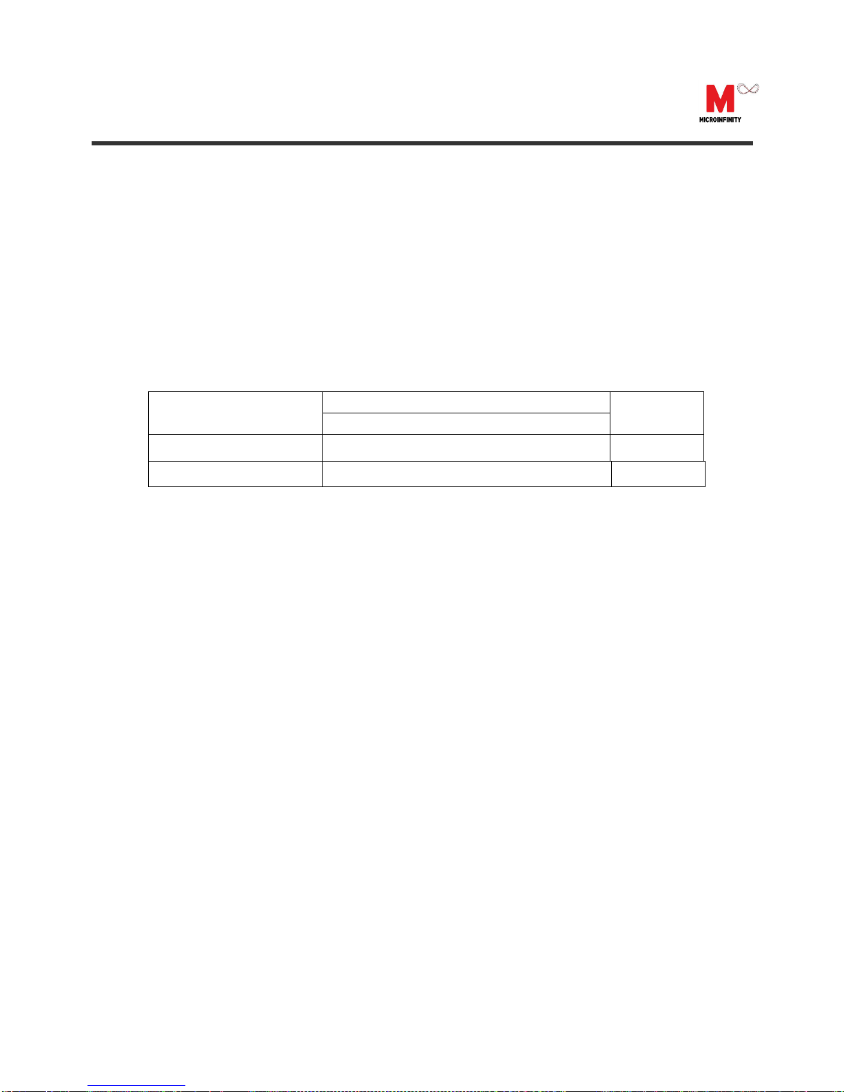
4.1. Physical Characteristics
Table 3: CruizCore®XG1350 physical characteristics.
PARAMETER
VALUE
UNIT
Min.
Typ.
Max.
SIZE
35.9 × 35.9 ×17.0
mm
WEIGHT
15
g

CruizCore®XG1350 USER MANUAL
Microinfinity reserves all rights in this document and its subject matter. The recipient acknowledges these rights and assures the use of this document only for the purpose it was delivered.
11
4.2. Environmental Characteristics
Table 4: CruizCore®XG1350 environmental characteristics.
NO.
ITEMS
TEST CONDITION
TEST CRITERIA
1
High temperature
storage
85C x 120h
Refer to Table 5
2
Low temperature
Storage
-40C x 72h
Refer to Table 5
3
Temperature and
Humidity cycling
25C , 60%RH(4h) / 55C , 95%RH(10h)
/-30C(2h) / 75C(2h), 10cycles
Refer to Table 5
4
Thermal shock
-40C ↔ 85C 1hour at each
temperature,
10cycles
Refer to Table 5
5
Drop
Free drop from 750mm height
on a wooden board for 6 times
Refer to Table 5
6
Vibration
10Hz to 55Hz amplitude
0.75mm, 55Hz to 500Hz
acceleration 98m/s2,
10Hz→500Hz→10Hz
15min/cycle, 6h(2h x 3directions)
Refer to Table 5
7
ESD
R(330Ω) C(150pF), Contact
discharge, 5times
Refer to Table 5
* After each test, there should be no visible damage and the measured values shall be met
Table 5.
Table 5: Judgment criteria of environment and mechanical test
ITEMS
UNITS
JUDGMENT CRITERIA
Angular error
degree
360±1.0deg. (CW rotation)
0±1.0deg. (CCW rotation)
ESD
voltage
1kV(operating), 2kV(destruct)

CruizCore®XG1350 USER MANUAL
Microinfinity reserves all rights in this document and its subject matter. The recipient acknowledges these rights and assures the use of this document only for the purpose it was delivered.
12
4.3. Electrical Characteristics
Table 6: CruizCore®XG1350 electrical characteristics.
PARAMETER
CONDITION
VALUE
UNIT
Min.
Typ.
Max.
INPUT VOLTAGE
OPERATING
4.75
5.25
V
RECOMMENDED
5
V
CURRENT
@ 5 V
10
mA
POWER
@ 5 V
50
mW
CAUTION
ESD (electrostatic discharge) sensitive device.
Electrostatic charges as high as 4000 V readily
accumulate on the human body and test equipment and
can discharge without detection. Permanent damage may
occur on devices subjected to high-energy electrostatic
discharges. Therefore, proper ESD precautions are
recommended to avoid performance degradation or loss
of functionality.

CruizCore®XG1350 USER MANUAL
Microinfinity reserves all rights in this document and its subject matter. The recipient acknowledges these rights and assures the use of this document only for the purpose it was delivered.
13
4.4. Performance Characteristics
Table 7: CruizCore®XG1350 performance characteristics.
PARAMETER
VALUE
UNIT
Min.
Typ.
Max.
BANDWIDTH
RATE
10
50
Hz
WARM-UP TIME
FAST WARM-UP
0.5
sec
FULLALIGNMENT1
5
min
ANGULAR RATE
CONTINUOUS*
100
deg/sec
INSTANTANEOUS2
150
deg/sec
RESOLUTION
0.01
deg/sec
SCALE FACTOR
ERROR
0.5
1
%
BIAS DRIFT
< 10
50
deg/hr
ACCELERATION
MEASUREMENT
RANGE
2
G
DATA RATE
ADJUSTABLE3
100
Hz
* The system must be installed in the correct position.
1. Full alignment: The total time that takes for full bias error calibration and temperature compensation. It is the worst
case on condition that the temperature goes up suddenly without temperature compensation.
2. Prolonged time in this condition will introduce heading errors
3. Other data rate available as option.

CruizCore®XG1350 USER MANUAL
Microinfinity reserves all rights in this document and its subject matter. The recipient acknowledges these rights and assures the use of this document only for the purpose it was delivered.
14
BLANK
PAGE

CruizCore®XG1350 USER MANUAL
Microinfinity reserves all rights in this document and its subject matter. The recipient acknowledges these rights and assures the use of this document only for the purpose it was delivered.
15
Contact Information
Corporate Office
Microinfinity Co., Ltd.
8F KANC, 906-10, Iui-dong,
Yeongtong-gu, Suwon-si
Gyeonggi-do, 443-270, Korea
Tel : +82-31-546-7408
Fax : +82-31-546-7409
Email: support@minfinity.com
USA Technical Support
P.O. Box 131284
Ann Arbor, MI 48105, USA
Tel : +1-734-223-5904
Fax : +1-866-400-3125
Email: usa.support@minfinity.com
Homepage: http://www.minfinity.com
Table of contents
Popular Science Education Product manuals by other brands

SPECTRO
SPECTRO FES 27 Original operating instructions

TruCorp
TruCorp AIRSim Pierre Robin user manual

Alga Science
Alga Science HDMICROSCOPE manual

Kyoto Kagaku
Kyoto Kagaku MW45 quick start guide

KOKEN
KOKEN Western Features Baby instruction manual

Scientific Explorer
Scientific Explorer Crystal Radio manual


3D Molecular Designs
3D Molecular Designs ENZYMES IN ACTION KIT 12-Group Set manual

WATSON INDUSTRIES
WATSON INDUSTRIES VSG-E469 owner's manual

Velleman
Velleman MICROBIT user manual

Copernicus
Copernicus UV Tech Tub user manual

Murata
Murata GYROSTAR ENC-03JA Operation manual

InVento
InVento Star Coaster instruction manual