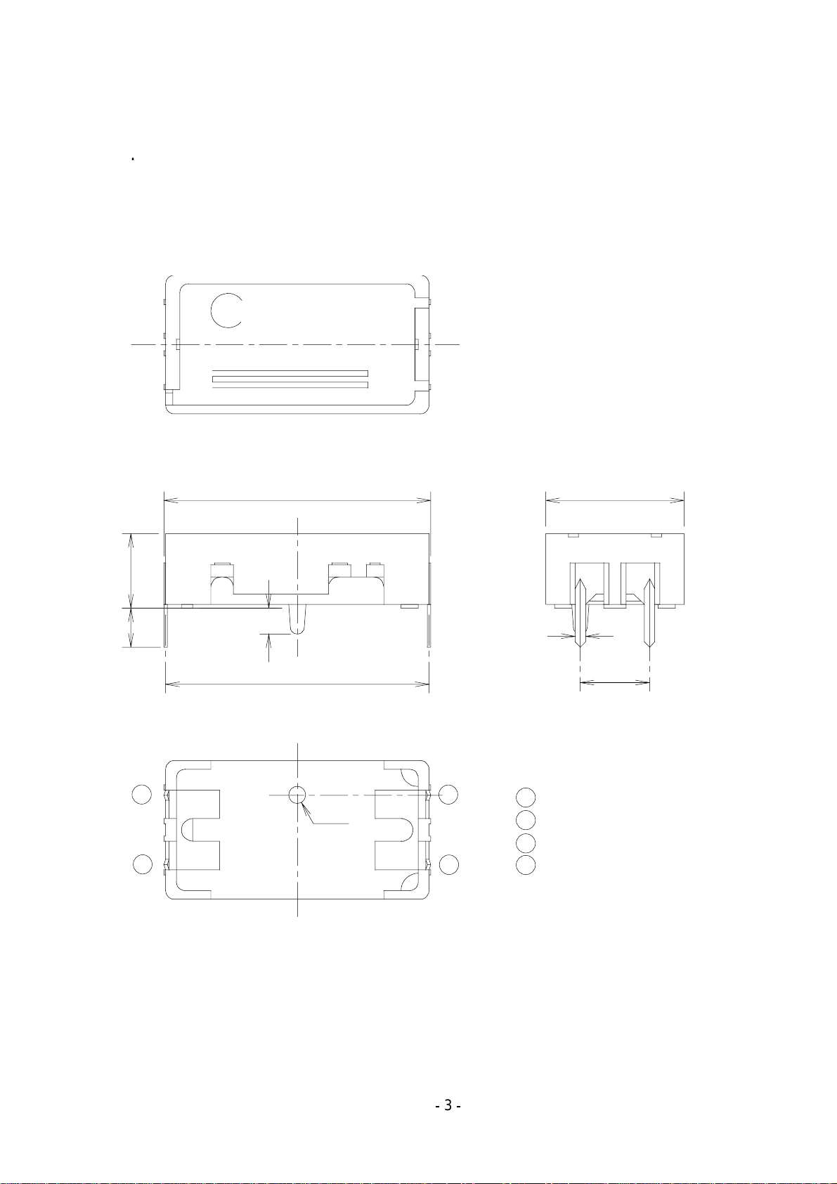
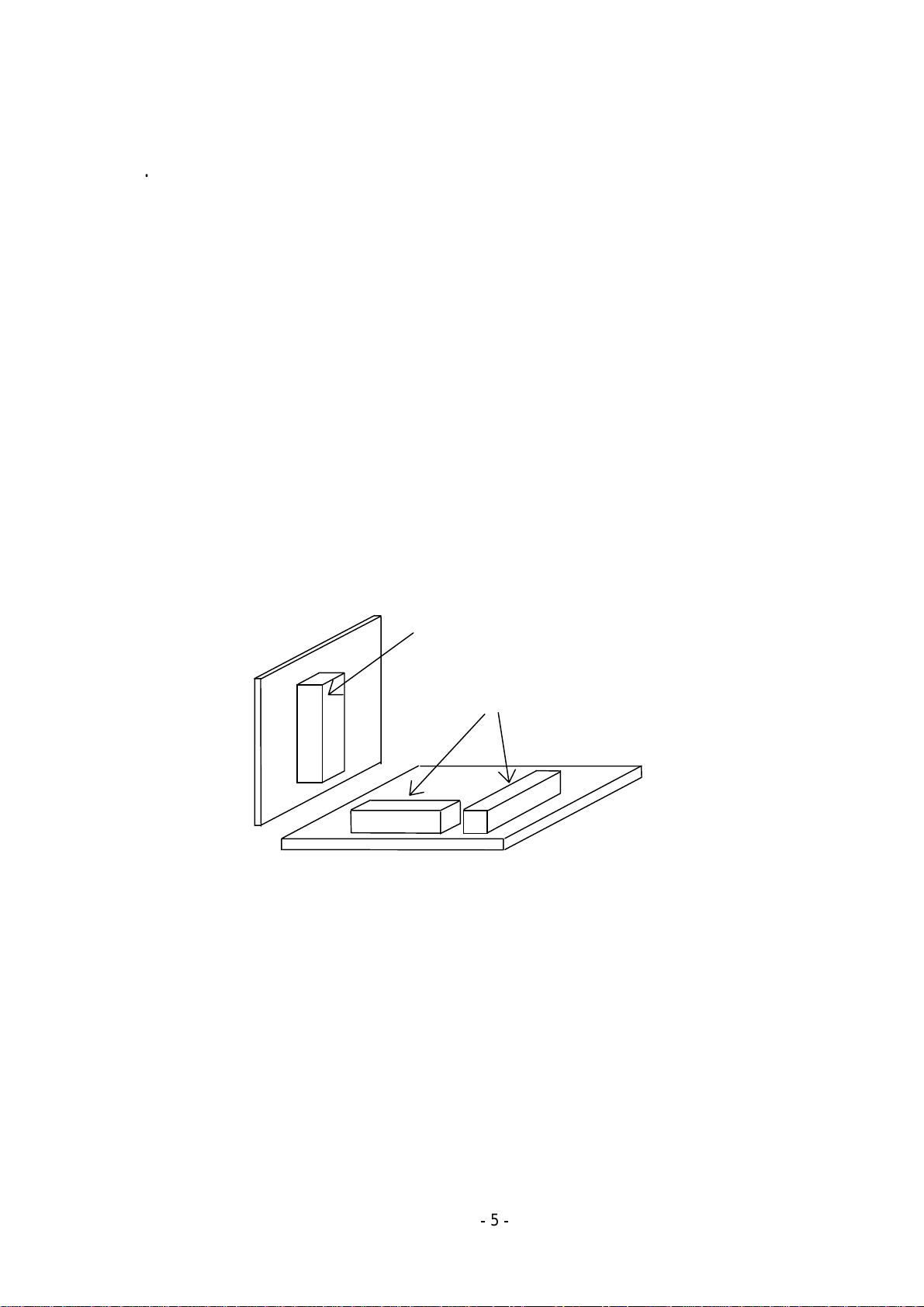
Murata GYROSTAR ENC-03JA User manual

OPERATION MANUAL
OF
GYROSTAR®
Piezoelectric vibrating Gyroscope
MODEL : ENC-03J TYPE
Support sensor for
video camera
May 6, 1999
PRODUCT ENGINEERING SECTION
SENSOR MODULE DEPERTMENT
CIRCUIT PRODUCTS DIVISION
MURATA MFG. CO., LTD.

ENC-03J type
1
Introduction
This angular velocity sensor employs the principle that a Coriolis force results if an angular velocity
is applied to a vibrating object. Murata's unique ceramic bimorph vibrating unit is used as the
sensor element unit, thereby enabling piezoelectric ceramics to be used for both excitation and
detection. The use of this unit simplifies equipment structure and circuit configuration, thus making
it possible to provide outstanding performance.
This sensor can be used for positional control and posture control of a moving object requiring
high-precision measurements.
1. Features
- Ultra small and ultra lightweight
- Quick response
- Low driving voltage, low current consumption
- Reliable feature achieved by a built in AGC circuit
2. Applications
- Detecting hand movement involved in video and still camera
- Detecting vibrations in various vibration free table and isolators
- Detecting the own movement

ENC-03J type
2
3. Specifications
Type ENC-03JA and ENC-03JB
Characteristics Symbol Condition MIN. STD. MAX. Unit
Supply voltage Vcc +2.7 +3.0 +5.5 VDC
Current consumption Isup at Vcc = +3.0V 2.5 3.2 4.5 mA
Comparative voltage Vref at -5~+75°C +1.25 +1.35 +1.45 VDC
Static output (Bias) V0 angular velocity = 0
at -5~+75°C
Vref
-0.55
Vref Vref
+0.55
VDC
Angular velocity range ωmax +300 deg/s
Scale factor Sv -20% 0.67 +20% mV/deg/s
Temp. coefficient of
scale factor
Reference : Ta
at -5~+75°C
-20 - +10 %FS
Resonance frequency
- version ENC-03JA
- version ENC-03JB
fa
fb
-
-
22
24
-
-
kHz
kHz
Resonance frequency
disparity
fa-fb at -5~+75°C 1 - - kHz
Linearity in the maximum
angular velocity range
-5 - +5 %FS
Response Phase delay : 90deg DC ~ 50 Hz
Operating temp. range Topr -5 - +75 deg C
Storage temp. range Tstg -30 - +85 deg C
Weight - - 1.0 g
Dimension Refer to page 3 15.5 x 8.0x 4.3 mm
All typical values
Unless otherwise specified, ambient temperature Ta= 25+/-5deg C, Vcc = +3.0 VDC
Use a sensor output load resistance of 50kΩor more.
Comparative voltage (Vref) is grounded with condenser of 4.7µF.

ENC-03J type
3
4. Dimensions
All dimensions are in "mm"
Measurement tolerance = +/- 0.2mm
2.25
1.5
15.24
3
2
ø1.0
4
1
4.3
15.44
03JA
MJPN
841
0.6
3.81
Vcc
1
Out
Vref
Gnd
3
4
2
8.0

ENC-03J type
4
5. Installation
1) Install the sensor by using the bottom face as the reference point.
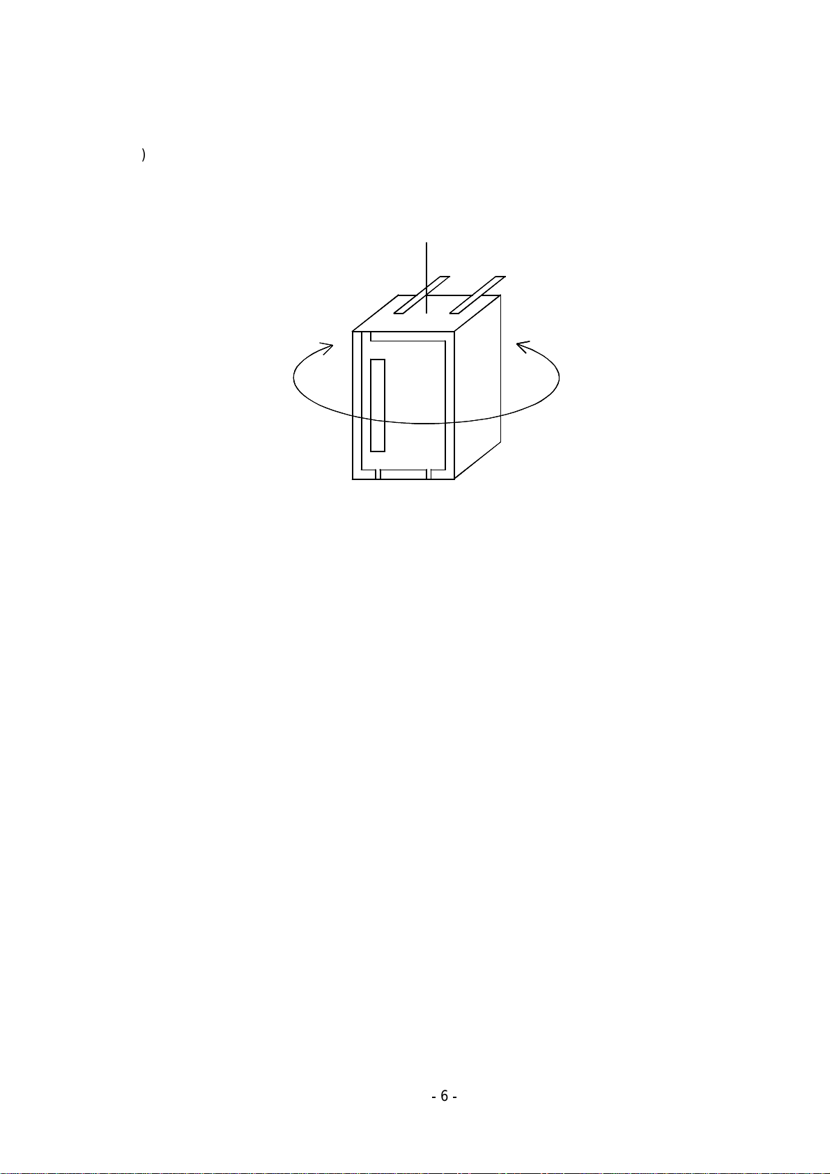
2) Install the sensor vertically with respect to the rotating surface. (90 +/- 5 deg )
3) Install the sensor in a location which minimizes excessive vibration (ex. Model helicopter
application) and use elastic materials to absorb external shock and vibration.
Typically, the sensor can withstand vibration that frequency 10~55Hz, amplitude 1.5mmp-p,
duration 2hours.
4) Install the sensor in a place which minimizes substantial temperature variations.
5) When installing the sensor, terminals should be hand soldered onto the PCB.
Observe the following guideline, otherwise, characteristics may vary due to excessive soldering
heat:
320 +/- 10deg C, 2s or less.
6) Do not bend terminals.
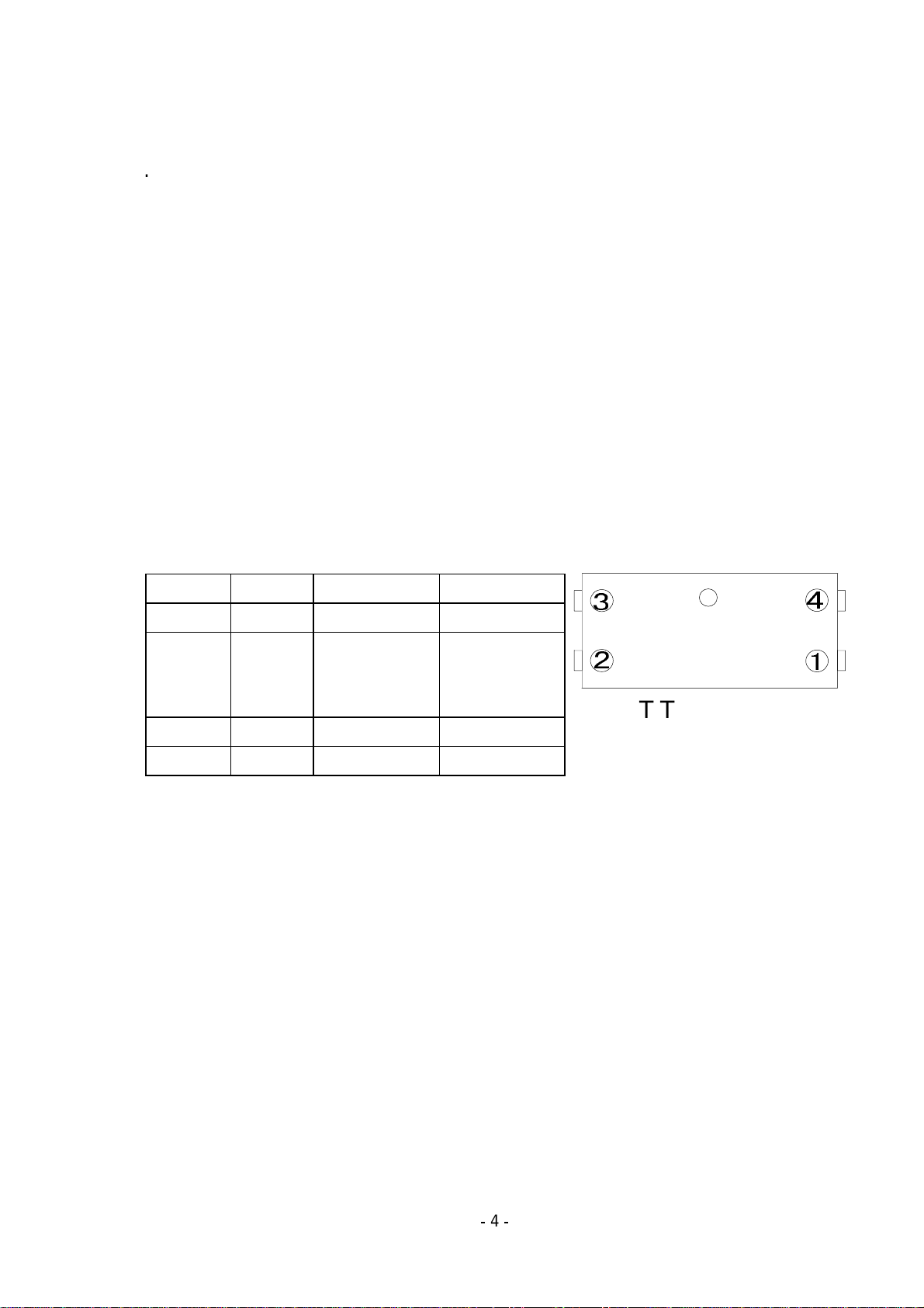
6. Terminal connection
Terminal Symbols Descriptions
1 +Vcc Supply voltage [input]
2 Vref Comparative
voltage(approx
.+1.35V)
[output]
3 GND Ground [common]
4 OUT Sensor output [output]
7. Connection
1) Operation voltage is +2.7V to +5.5V.
Use a stabilized power supply free from surge and ripple voltages. Also, Confirm proper power
supply polarity before connecting sensor.
2) Output voltage is relative to the angular velocity.
Output voltage = V0 + Sv x ω[V]
V0 :Static output [V] (at angular velocity is 0 [deg/s])
Sv :Scale factor [mV/deg/s]
: Angular velocity [angular velocity range : -90 to +90 deg/s]
3) Use a sensor output load resistance of 50kΩor more.
4) Comparative voltage (Vref) must be grounded with condenser of 4.7µF or more.
5) Comparative voltage is used as a reference voltage of amplification. (Refer to page 7)
BOTTOM VIWE

ENC-03J type
5
8. Notice
1) ENC-03J can detect angular velocity along only one axis.
When using more than one of the same type ENC-03J at the same time, swelling may result on the
output due to the mutual interference with sound waves of each sensing devices resonant
frequency. Therefore, there are 2 types of the ENC-03J. One is the ENC-03JA and other is
ENC-03JB. The ENC-03JA has the same specifications as the ENC-03JB with the exception of the
resonant frequencies. By using different frequencies, mutual interference can be avoided.
When detecting just one axis, select model ENC-03JA.
When detecting two axes, select models ENC-03JA and ENC-03JB.
When detecting three axes, select 2 pcs of ENC-03JA and 1pc of ENC-03JB and follow the bellow
guideline to avoid mutual interference:
Install one ENC-03JA on a separate PCB from the other installed ENC-03JA.
Even while both devices aremounted on separate PCB’s, it is critical that the two devices are still
kept apart as far as possible.
Use acoustical material in order to isolate the sound wave.
ENC-03JA
ENC-03JA and ENC-03JB

ENC-03J type
6
2) Confirm the proper mounting direction before installing the sensor.
JPN
M
Clockwise
Positive voltage(+)
03JA 822
Counter clockwis
Negative voltage
(
Sensing axis
3) Bias and scale factor drift
Surrounding temperature variation may affect the sensor output (bias, scale factor). Sensor
should be mounted where temperature does not vary significantly.
When canceling bias drift, please refer to the following examples.
- Cut DC level along output by using a HPF (Hi-Pass-Filter) with a low cut-off frequency on the
sensor output. ( Refer to page 7)
9. Handling
1) Incorrect handling may affect the sensor characteristics. Please note the following precautions;
A. Do not subject the sensor to shocks which exceed the rated limit.
Typically, the sensor can withstand shock peak to 500G, duration 1msec, half sine wave.
B. Do not install or store the sensor in a location where condensation is likely to form on it.
C. Do not install or store the sensor in a location where water may splash directly on it.
D. Do not install or store the sensor in a location in which it is likely to be exposed to salt water or
corrosive vapor.
2) Precision electronic parts, such as ICs, are used for the sensor; therefore, it is necessary to take
anti-static precautions when handling.
3) Do not wash the sensor, as it is not water resistant.
4) Do not disassemble.

ENC-03J type
7
10. Application
A simplified block diagram is shown in the illustration.
Micro processor
A/D converter
GYROSTAR
ENC-05E
Band pass
filter Amplifier
High-pass,
Low-pass
1) Positive voltage(+) and negative voltage(-) are obtained in the clockwise and counterclockwise
directions, respectively, with the static output as a reference.
2) Cut DC level of output using HPF (Hi-Pass-Filter) with low cut-off frequency on sensor output In
order to cancel bias drift. Cut-off frequency of HPF will affect measurement accuracy. Please
choose a proper cut-off frequency according to the application.
3) Always use an A/D converter of 8 bits or more. Resolution of A/D converter will affect
measurement accuracy . Please choose a proper resolution according to the application.
4) The sampling frequency used for measurement should be 50 times/sec minimum. Sampling
frequency will affect measurement accuracy . Please choose a proper sampling frequency
according to the application.
5) Please choose a proper amplification factor according to the application.
6) Typical circuit NJM2115 or equivalent
NEW JAPAN RADIO CO., LTD.
ENC-03J
3V Vcc
1
Out
GND Vref
4.7µF
100k
10k
4.7µF
90k
1800pF
V
High-pass filter
Low-pass filter
2
3
4
The high-pass filter’s cut-off frequency in this circuit is approx. 0.3Hz. The low-pass filter’s cut-off
frequency in this circuit is approx. 1kHz.

ENC-03J type
8
Note
1) Please contact our sales representatives or product engineers before using our products listed in
this catalog for the applications listed below which require especially high reliability for the
prevention of defects which might directly cause damage to the third party’s life, body or property,
or when intending to use one of our products for other applications than specified in this catalog.
(1) Aircraft equipment
(2) Aerospace equipment
(3) Undersea equipment
(4) Medical equipment
(5) Transportation equipment (vehicles, trains, ships, etc.)
(6) Traffic signal equipment
(7) Disaster prevention / crime prevention equipment
(8) Data-processing equipment
(9) Applications of similar complexity or with reliability requirements comparable to the
applications listed in the above.
2) Product specifications in this catalog are as of May, 99. They are subject to change or our
products in it may be discontinued without advance notice. Please check with our sales
representatives or product engineers before your ordering. If there are any questions, please
contact our sales representatives or product engineers.
3) The parts numbers and specifications listed in this catalog are for information only. You are
requested to approve our product specification or to transact the approval sheet for product
specification, before your ordering.
This manual suits for next models
1
Table of contents