CruzPro LA-20B User guide

O
w
n
e
r'
s
O
w
n
e
r'
s
Handbook
Handbook
Warranty
Each unit is carefully tested and adjusted
at the factory before shipping and is
warranted for one full year against original
defects in materials or workmanship. This
warranty does not include damage to the
product resulting from accident or misuse.
If the product should become defective
within the warranty period, we will repair
or replace it free of charge, including free
return transportation, provided it is
delivered prepaid to the dealer from whom
it is originally purchased.
This warranty gives you specific legal
rights, and you may also have other rights
which vary from state to state, or country
to country.

Table of Contents
Introduction . . . . . . . . . . . . . . . . . . . . . . . . . . 4
Specifications . . . . . . . . . . . . . . . . . . . . . . . . . 5
Installation . . . . . . . . . . . . . . . . . . . . . . . . . . . . 6
CruzPro Instrument Connection Table . . . . . . . 9
Other CruzPro Products . . . . . . . . . . . . . . . . . 10
Warranty . . . . . . . . . . . . . . . . . . . . . . . . . Back Cover
1997 BV Engineering
V1.0
Page 3
Page 10
Page 8
Specifications
Operating Voltage: 9.5 to 18 VDC, 0.020 ampere
nominal (0.35 amps maximum when activated).
Operating temperature: 0 to 50 deg Celsius ( 32
to 122 deg Fahrenheit)
Size: 100 x 60 x 30 mm (4 x 2.4 x 1.2 inch).
Alarms: Built-in 105 dB audible alarm. Output
connection to flash spreader, anchor or running
lights (8 amps maximum).
Reset Button: Silences the alarm for 4 out of the
5 inputs. Re-arms automatically when inputs
clear.
Inputs: Five inputs on screw terminals. Three
activate the alarm if they are grounded or go low
(below 5 VDC). Two activate the alarm if they go
high (+2 to +33 VDC). One of the latter bypasses
the RESET button and cannot be turned off at the
LA-20 (it must be turned off at the source).
Page 5
circuit approximately twice per second to draw
attention to your boat. The "O" output terminal can
supply a maximum of 8 amps. A side effect of
connecting the "O" output to your light circuit is
that the alarm will sound briefly every time you
turn on the light manually, unless power is always
supplied to the LA-20.
After connecting the signal lines, connect the
ground wire to a common ground point and the
+12 VDC wire to your +12 VDC distribution point
as shown in Figure 1. As soon as you connect
power to the LA-20B, it will sound the alarm for
two or three seconds. It will be very loud so be
prepared.
Re-install the cover on the case back. Do not
overtighten the case front screws.
See full details at http://www.cruzpro.com
Other CruzPro Products
lDepthsounders & Speed/Temperature/Log
lDC Volts/Amps/Amp-Hour Monitor
lAC Volts/Amps//Freq/kW Monitor
lLPG/Petrol Gas Detectors/Alarms
lBilge Water Alarms & Bilge Pump Controllers
lWindlass Controller/Chain Counter
lDigital Fuel Gauge & Fuel Consumption Calculator
lDigital Gauge for Three Tanks /w Separate Alarms
lSmart and Manual Alternator Regulators
lMarine Security System
lRPM/Engine Hours/Elapsed Time Gauge
lDigital Oil Pressure Gauge/Alarm
lDigital Water Temperature Gauge/Alarm
lOne and Three Bank Digital Volts Gauges
lDigital Amps Gauge
lDigital Clock/Watch/Race Timers/Alarms
l8 and 16 Amp Light Dimmers / Motor Speed Controller
lSolar Panel Charge Controllers 6/8/9 & 20 Amps
l4 & 8 Channel NMEA Combiners/RS-232 Convertors
lEngine/Exhaust Temp. Monitor & Digital Pyrometer
lDigital Clock with four 4 amp electronic timer switches

Introduction
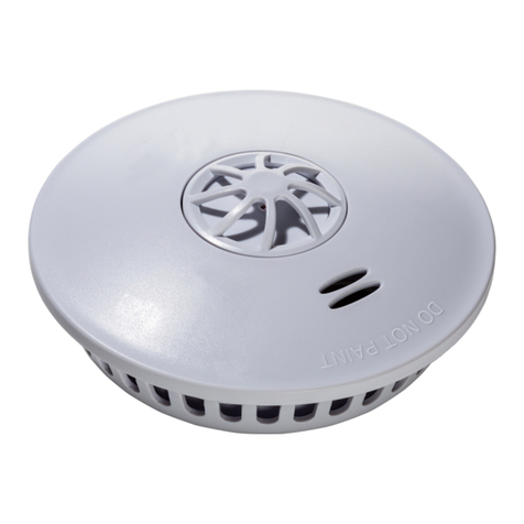
The LA-20B External Multi Alarm with 8 amp
light flashing circuit has five alarm input terminals
and connects up to five instruments to provide an
amazing loud 105 dB alarm volume that can be
seen and heard for 1/4 mile or more.
All connections are to screw terminals simplifying
installation and requires only a screwdriver. Four
of the five alarms can be turned off by pressing the
RESET button, one purposely bypasses the RESET
button and must be turned off at the source.
Two different types of inputs are provided. Three
inputs activate the alarm if any one of them go
below 5 VDC. The other two inputs activate the
alarm if one of them goes high (+2 to + 33 VDC).
One of the latter bypasses the RESET button
(cannot be turned OFF at the LA-20B).
If the LA-20B is silenced by pressing the RESET
button, it automatically re-arms itself when all the
inputs are in a clear state.
Page 4 Page 9
Installation
Remove the case front and align the case back onto
any suitable surface. The case is not waterproof
and should be mounted in a dry place. Use the case
back as a drill guide, mark the location of the two
holes with a pencil. Drill two 2mm (3/32 inch)
holes and mount the case back using the screws
provided. To hide the wires, use the rear exit with
the enclosed spare rubber grommet.
Thread two 16 gauge wires through the rubber
grommet on the case front (or rear) and connect to
the terminals marked "+12V" and "GND" in Fig-
ure 1. Connect the alarm inputs using 22 gauge (or
larger) wire. Signals connected to the terminals
marked "L" in Figure 1 will activate the alarm if
they go low (below 5 VDC). Signals connected to
terminals marked "H" in Figure 1 activate the
alarm if they go high (+2 to +33 VDC). The signal
connected to terminal "HB" activates the alarm if
it goes high (+2 to +33 VDC), bypasses the RESET
button and cannot be silenced at the LA-20. See
the chart on page 9 for the correct connection
points
Page 6
for CruzPro instruments.
If desired, connect a 16 guage wire from terminal
"O" to your spreader, anchor, or running light
circuit. When the LA-20B alarm sounds, The "O"
output terminal switches +12VDC to your light
Figure 1 - Connection Diagram
Page 7
CruzPro Instrument Connection Table
The following CruzPro instruments are designed to
connect to the LA-20 as shown below:
Instrument LA-20 Terminal
CC-20 8 Amp Charge Controller L
CC-30 20 Amp Charge Controller L
GD-20 LPG/CO Gas Vapor Alarm H
SA-20 Security System/Alarm HB
EFS-20 Dual Bilge Pump Controller L
EFS-10 Bilge Pump Controller L
BBA-20 Three Bank Battery Monitor L
AC-20 Manual Alternator Controller L
ETM-20 Engine Temperature Monitor L
BWA-20 Bilge Water Alarm L
DT-20 Dual Electronic Timer/Switch H
NC-20 NMEA Combiner H
RH30 Digital RPM Gauge H
OP30 Digital Oil Pressure Gauge H
VAH35 3 Bank Volts/Amps/A-H Monitor H
V30 3 Bank Digital Volts Gauge H
A30 Digital Amps Gauge H
A maximum of six CruzPro instruments can be
connected to one LA-20.
