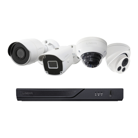
Nice HSCU1 Technical specifications

EN - Instructions and warnings for installation and use
0682
Home security control unit
Nice
HSCU1
EN50131 Grade 1

EC DECLARATION OF CONFORMITY
Declaration in compliance with Directive 1999/5/EC
Note – The content of this declaration corresponds to that specified in the official document deposited at the Nice S.p.A. headquarters and, in
particular, to the latest revised edition available prior to the publishing of this manual. The text herein has been re-edited for editorial purposes. A
copy of the original declaration can be requested from Nice S.p.A. (prov. of Treviso – Italy)
Number: 305/HSC... Revision: 6 Language: EN
The undersigned, Mauro Sordini, in the role of Chief Executive Officer, declares under his sole responsibility, that the product:
Manufacturer’s Name: NICE S.p.A.
Address: Via Pezza Alta 13, Z.I. Rustignè, 31046 - Oderzo (TV) Italy
Type of product: Supervised and tele serviceable standard control panels, powered with 230V mains power and
battery power, with or without GSM module
Model: HSCU1GC, HSCU1C, HSCU1G, HSCU1
Accessories:
Complies with the essential requirements pursuant to Article 3 of the following European directive, relevant to the use for which
the products are intended:
• DIRECTIVE 1999/5/EC OF THE EUROPEAN PARLIAMENT AND OF THE COUNCIL of 9 March 1999 on radio equipment and
telecommunications terminal equipment and the mutual recognition of their conformity, in accordance with the following har-
monised standards:
- Health and safety (Art. 3(1)(a)): EN 62479:2010, EN50360:2001+A1:2012
- Electrical safety (Art. 3(1)(a)): EN 60950-1:2006 + A11:2009 + A12:2011+ A1:2010+A2:2013
- Electromagnetic compatibility (Art. 3(1)(b)): EN 301 489-1 V1.9.2:2011, EN 301 489-3 V1.6.1:2013, EN 301 489-7
V1.3.1:2005
- Radio spectrum (Art. 3(2)): EN 300 220-2 V2.4.1:2012, EN 301 511 V9.0.2:2003
In accordance with Directive 1999/5/EC (appendix V), the product is class 1 and marked:
Moreover, the product complies with the specifications of the following harmonised directives:
EN 50130-4:2011
Oderzo, 30 June 2014
Ing. Mauro Sordini
(Chief Executive Officer)
0682

1
Contents
1 – ESTABLISHED LEGISLATION, WARNINGS AND GENERAL
PRECAUTIONS ......................................... 2
1.1 - General warnings..................................... 2
1.2 - Supplementary warnings for mains powered devices.......... 2
1.3 - Warnings about installation ............................. 2
1.4 - Regulations EN50131 ..................................2
2 - PRODUCT DESCRIPTION AND INTENDED USE .............. 2
2.1 - General specifications ................................. 2
2.2 - Differences between the two models of control panel.......... 2
2.3 - System implementation - Installer’s responsibilities............ 2
3 - DESIGNING AN ALARM SYSTEM .......................... 3
3.1 - Distributing the protected areas in the home ................ 3
3.2 - Positioning the alarm system components .................. 3
3.3 - Elements of the Nice Home Security alarm system ........... 6
4 - INSTALLATION: control panel and accessories ............... 8
4.1 - Setting up the system components for configuration .......... 8
4.2 - Preliminary checks before installation and limitations on use .... 8
4.3 - Description of the control panel .......................... 8
4.4 - INSTALLATION Control panel (models HSCU1GC - HSCU1C and
HSCU1G - HSCU1) ....................................... 9
5 - ELECTRICAL CONNECTIONS ............................ 12
5.1 - Important warnings .................................. 12
5.2 - Control panel connections (models HSCU1GC
and HSCU1C only)....................................... 12
5.3 - HSSOC siren connections ............................. 12
6 - PROGRAMMING THE CONTROL PANEL ................... 14
6.1 - Programming procedure .............................. 14
6.2 - Programming messages .............................. 14
6.3 - Digital protocols..................................... 17
6.4 - Programming alarm systems / Wireless warning ............ 19
7 - MAINTENANCE ........................................ 19
7.1 - Replacing the batteries (control panel and accessories) ....... 19
8 - WHAT TO DO IF... (troubleshooting) ....................... 21
SCRAPPING........................................... 21
9 - USER MANUAL ........................................ 22
9.1 - Access codes ...................................... 22
9.2 - Access levels ....................................... 22
9.3 - Function keys .......................................22
9.4 - User access for configuration (table 1) .................... 22
9.5 - User access for operation (table 2)....................... 23
9.6 - Access for manoeuvres - arming/disarming the control panel .. 25
9.7 - Alarm functions ......................................25
9.8 - User remote control - domotic functions
(uncertified characteristics) ................................. 26
9.9 - User Information .................................... 27
10 - ELECTRICAL SPECIFICATIONS .......................... 27
QUICK PROGRAMMING GUIDE.............................. 29

2
1.1 - General warnings
• This manual contains important information regarding the safety
of the installation; before installing the components, it is important
that you read all the information contained herein. Keep this manual
for future use. Further information is available at: “www.niceforyou.com”.
• In case of doubt during the installation, do not make fruitless attempts, but
contact NICE customer service.
• The product/s may not be used for any purpose other than that indicated in
these instructions.
• Do not make modifications to any components unless such action is speci-
fied in this manual. Operations of this type are likely to lead to malfunctions.
NICE disclaims any liability for damage resulting from modified products.
• Depending on the specific circumstances, further devices may be required,
whether detectors or signalling equipment.
• When installing and using the product, make sure that foreign matter (solid
or liquid) does not enter the devices when they are open.
• The packaging materials must be disposed of in compliance with the local
regulations.
• Manufacturer's responsibility: Nice declines all liability for faults resulting
from incorrect installation, maintenance and use. Furthermore, Nice is not
liable for the incorrect or incomplete function of the product.
• Warranty (summary of terms):
Nice guarantees its products against concealed faults for a period of 3
years from the date of manufacture. The warranty applies to Nice's direct
clients; no warranty is applicable to the end user, who must contact their
installer/reseller in case of malfunction.
• Exclusions: the following are excluded from the warranty: aesthetic com-
ponents, parts subject to normal wear and tear and consumables such as
batteries and accumulators.
1.2 - Supplementary warnings for mains powered devices
• This manual has been especially written for use by qualified fitters.
• Considering the hazards that may exist during the installation and operation
of the system, for reasons of safety installation must be carried out in strict
compliance with current legislation, standards and regulations.
• Disconnect all power connections before accessing the product's internal
terminals.
• If an automatic switch or a fuse is tripped, identify and eliminate the reason
before resetting it.
1.3 - Installation warnings
• Check that all the materials are in good working order and suited to the
intended applications.
• Check that the radio frequencies used by the product are locally approved
for use in alarm systems.
• The individual articles are designed per the following 2 environmental class-
es
- Class II environment: general indoors use; temperature -10 to 40°C, aver-
age humidity 75% without condensation
ESTABLISHED LEGISLATION, WARNINGS AND GENERAL PRECAUTIONS
1
- Class III environment: protected outdoors use; temperature -25 to +50°C,
average humidity 75% with peaks of 30 days a year of 85 to 95%; without
condensation.
• Before installing the equipment, check the products' environmental class in
the Technical Specifications chapter.
• Check that the wireless range of the devices (as given in the Technical
Specifications chapter) is greater than the physical distance between the
products.
• Make sure that the mounting positions of devices (sensors, control panels,
etc.) are protected from impact and that the mounting surfaces are suf-
ficiently sturdy.
• Do not locate the products close to strong sources of heat as this may
damage them.
• Each sensor has its own principle of operation: check the suitability of their
intended locations against the warnings given in the respective user manu-
als.
1.4 - Regulations EN50131
• When used with the EN50131 setting enabled, and in accordance with the
limits and/or specific information provided for each application, the control
units are compliant with the above standards. Any adjustments/programming
must be done in observance of the established limits.
PRODUCT DESCRIPTION AND INTENDED USE
2
2.1 - GENERAL SPECIFICATIONS
Nice Home System systems are intended for alarm and domotics control and
management, in which all devices and their functions are programmed within
the context of an alarm system.
Some control panels may be connected by cabled to a variety of accessories,
used to control the control panel, detect a variety of phenomena and generate
warning and deterrent alarms, as well as domotics control boards.
2.2 - DIFFERENCES BETWEEN THE TWO MODELS OF CON-
TROL PANEL
Nice Home System control panels are powerful devices, suited for small to
medium sized installations, from 1 to more than 90 detectors. Depending on
the type and size of installation, there are four models to choose from. They
differ in their power supply options and whether they have integrated GSM-
GPRS modules. These differences are native, so that it is not possible to add
the missing elements to a less fully featured model.
All control panels have integrated PSTN (landline) phone transmitters.
HSCU1GC: primary 230V mains power – integrated GSM/GPRS module
HSCU1C: primary 230V mains power – no GSM/GPRS module
HSCU1G: primary alkaline battery power, no 230V mains power – integrated
GSM/GPRS module
HSCU1: primary alkaline battery power, no 230V mains power – no GSM/
GPRS module
IMPORTANT: this manual covers the features of the most complete model,
the HSCU1GC. Any functions described in this manual which require the GSM/
GPRS module will be lacking from models not equipped with the module in
question. In the same way, any functions dependent on mains power will be
lacking from the “free”, battery powered models. This manual therefore covers
the features of all models, but simply indicates which features are lacking from
certain models due to the above-mentioned characteristics. Examples:
a) Models without the GSM/GPRS module do not require a SIM card, and do
not send SMS's, and therefore do not require the messages in question to be
programmed. They can only be called via the PSTN landline. b) Models without
mains power, and hence battery powered, do not have wired inputs/outputs
and cannot power the GSM/GPRS module (if present) continuously; this must
be activated expressly on the control panel itself or by an alarm.
2.3 - SYSTEM IMPLEMENTATION - INSTALLER'S RESPONSI-
BILITIES
Every alarm system is composed of a variety of peripherals, detectors, sirens,
control locations, keyboards and so on, all controlled by one of the control
panels covered by this manual. It describes the control panels in full, along with
their intended applications and operation. The installer has the basic responsi-
bility of identifying the functionality required by the client, providing the neces-
sary security solutions and installing the equipment with diligence and profes-
sionalism. To enable the user to control all the functions provided, this manual
must be supplemented by the installer with remarks on the settings he has
made.
3
DESIGNING AN ALARM SYSTEM
3
In order to obtain an alarm system which is perfectly functional and suited to
the task in question, the installation must be designed in advance, before pro-
ceeding with the operations described in this manual. In particular, one must
determine the number, type and location of the sensors in relation to their vari-
ous functions. We advise drawing a plane diagram of the building, specifying
the name and position of each device to be installed. This diagram will be a
great help during system configuration, for instance when one has to memorize
the names of the various devices.
3.1 - Distributing the protected areas in the home
The control panel can be programmed to monitor the entire living area, or only
parts thereof. It is therefore important to start by dividing the entire area into
three action groups (group A- B- C), and assign each room or area to one of
these 3 groups, logically and functionally.
For detached houses, the first approach is to divide the entire area into con-
centric circles (see fig. 1). In this system one assigns, as an example: the out-
doors detectors = group A; the perimeter detectors (doors and windows) =
group B; the indoors detectors = group C. This division enables one to use the
siren vocal messages to dissuade persons from violating group A even before
they have started to do so, or trip the siren alarm at the first attempt to break
in through the doors and windows (group B), or call the police only when the
indoors detectors (group C) are tripped.
Another approach is to divide the area into homogeneous blocks (see fig. 2). In
this system one assigns, as an example, the ground floor areas to group A, first
floor area to group B and the garages to group C. This division enables one,
for instance, to activate the garage alarm (group C) while using the rest of the
house normally.
3.2 - Positioning the alarm system components
To determine the locations of the system components, we recommend refer-
ring to fig. 3 and checking the following conditions:
• Control panel
- Control panels transmit and receive lower power radio signals (within regula-
tory limits), and must therefore be located in such a way as to enable effective
signal propagation. The following are therefore excluded: niches, metal cabi-
nets, reinforced concrete columns and walls; furthermore, the control panel
should not be installed in the vicinity of large metal surfaces or grilles, includ-
ing any such features as are built into the walls.
- The control panel is best located at the centre of the other devices.
- The quality of the received signal can be seen on the control panel's display
(see 9.5.1.3 “FIELD METER test”) and if in doubt, we recommend running this
test before mounting the unit to the wall. With radio devices, even moving
them just a few tens of centimetres can significantly improve their transmis-
sion and reception.
- The control panels are equipped with a keyboard for programming them dur-
ing installation and for daily use of certain functions, such as arming/disarm-
ing the alarm. If you wish to use these functions, you must place the control
1
group C
group B
group A
group B
group A
group C
2

4
panel in an easily accessible position - normally next to the main entrance.
- If you wish to use the landline connection, make sure that it is possible to
hook the unit up.
- Mains powered control panels must be located so as to make the mains
hookup possible.
• Keyboards
If, for aesthetic reasons or to enable electrical hookup, the control panel must
be located away from the main entrance, it is advisable to install a keyboard in
the vicinity.
If the house has multiple entrances, a keyboard should be installed at each.
The keypads may be wall-mounted or handheld, like a normal transmitter.
• Sirens
In isolated houses, we strongly recommend installing at least one outdoors
siren. This should be located in good view (even the sight of it is an effective
deterrent) but in such a way that it cannot be tampered with. Although the
sirens are properly protected for outdoors installation, it is best to install them
out of direct rainfall; the best location is under the gutter line or a terrace/bal-
cony.
The control panel has its own siren, but in large or multi-storey houses, we
recommend adding one or more indoors sirens in the main rooms.
In small apartments or in densely inhabited areas, an outdoors siren may not
be suitable; if so, you can use multiple indoors sirens to increase the deterrent
effect.
• Sensors
Choosing the right type of sensor and positioning them correctly is essential:
the wrong type of sensor, or an incorrectly positioned sensor may fail to detect
an intrusion or generate incorrect alarm signals. Each type of sensor operates
differently, Table 1 explains which sensors to choose.
3
HSDID11
HSDID11
HSDID11
HSDIM10
HSDIM12
HSDIM12
HSDIM24
HSSI
HSDID11
HSDIM10
HSDIM12
HSDIS01
HSDIM23
HSDOM21
HSDIW01
HSDIW01
HSCU1GC
HSCU1C
HSCU1G
HSCU1
HSSO1

5
5
4
Door sensor: an intrusion detector designed for use on doors and windows which reports the opening of the door or window when its magnet is moved
away from its body. The detector is generally installed to the fixed part of the door or window, opposite to the hinges, with the magnet attached to the mobile
panel. The protection function may be augmented by connecting a second sensor with NC or pulse contact to its terminals (in the latter case, cord detector
for roll-up shutters).
It has an NO input which can be used for connecting a flooding sensor, for instance.
Vertical shutter lens sensor: an intrusion detector designed for protecting doors and windows, with a shuttered lens which detects the movement of
persons within a limited field of view in front of the lens itself (fig. 4).
It can be installed on the ceiling, at the top centre of a door or window (normally between the window itself and the shutters or blinds) and in areas under
cover. The sensor has a second terminal for connecting a second sensor with NC or pulse contact (in the latter case, cord detector for roll-up shutters). This
augments the protection and optimises the coverage of the area being protected.
Volumetric sensor: an intrusion detector designed to protect rooms; it reports the movement of persons in the protected area. It can be wall or corner
mounted using a special bracket, with an optional jointed holder for tilting it down into the room if so desired (not provided).
It operates by detecting the movement of warm bodies; it should therefore not be used in areas subject to currents of warm or cold air, which can cause
false alarms. If the sensor is active and the room is inhabited by warm-blooded animals, one must install it in a position and at an angle to keep its detection
area 50-70 cm off the floor (fig. 5); it may also be necessary to reduce its sensitivity.
The sensor has a second terminal for connecting a second sensor with NC or pulse contact (in the latter case, cord detector for roll-up shutters). This aug-
ments the protection and optimises the coverage of the area being protected.
Volumetric sensors for large rooms: normal volumetric sensors are more than able to cover normally-sized living spaces. For very large rooms, sensors
are available which can cover ranges up to 12 m with s 120° field of view. This type of sensor is equipped with a sensitivity adjustment, used to calibrate the
size of the protected area.
Dual technology sensors: intrusion detectors for protecting rooms, using 2 different technologies (IR and microwave) to detect the movement of persons
in the protected area. IR technology detects body heat, while microwave technology uses the Doppler effect to detect movement (including cold objects).
The combination of these two technologies gives the most effective coverage and also reduces false alarms.
Outdoors sensors: sensors are generally designed for use in protected indoors rooms. They operate correctly in a relatively restricted range of tempera-
tures and are not completely protected against rainfall. Special sensors are available which are adapted for outdoors use with temperature ranges of as
much as -25 to +50°C, which are also completely weatherproofed. All such sensors are equipped with sensitivity adjustments to set the size of the protected
area and prevent false alarms caused by, among other things, normal moving objects (branches and leaves), small animals, insects, and so on.
Glass breakage sensors: a sensor that detects the breaking of glass panes (both normal and double-glazed). The detector is equipped with a microphone
specifically calibrated to recognise the sound of breaking glass; be aware that it can thus be tripped by similar sounds - like a glass shattering when it is
dropped. The sensor should therefore only be activated when there is no-one in the protected area capable of producing sounds which could trip the sensor.
False alarms can also be tripped by appliances which generate cyclic pressure variations in the room (air conditioners, fans, etc.).
Sound damping materials (such as curtains and carpeting) may reduce the sensitivity of the device.
The device is factory calibrated and cannot be adjusted.
For best detection results, the device should be installed in a rooms of 20 to 30 m2, 3 to 6 m away from the glass pane in question and at 2 m off the ground.
It should not be installed in rooms smaller than 10 m2, in very humid areas (such as bathrooms and kitchens) or in garages with large metal doors. Such
situations are critical and may cause false alarms.
Fine particle (smoke) sensor: a detector for detecting fine particles generated by combustion (fog or smoke effect) for residential applications. It uses a
photo-diode to detect the opacity of the air and reports the alarm both directly on site (with a buzzer) and wirelessly transmits it to the control panel. The
sensor can detect the event over a maximum surface of 6 x 6 m; it must be positioned at the centre of the ceiling. Smaller, but not square rooms, such as
corridors, must be equipped with more than one detector.
Flooding sensor: a sensor that detects flooding caused by leaks. It must be wall-mounted, at floor level (the internal sensor is around 1 mm off the ground)
and placed in an area where a water leak is likely to occur, such as next to a sink or washing machine.
If the floor is not flat, the sensor should be put at its lowest point. The sensor connects to the NO input of a compatible detector (e.g. HSDID11).
TABLE 1
2,5
h=2,30 m
1,5
1
0,5
2
24 6810
90°
2
2
4
4
24 6810

6
3.3 - Elements of the Nice Home Security alarm system
Control panel
The control panel controls the system itself; it receives information from the detectors, keyboards and transmitters,
and trips the siren or sends messages over the landline or cellular network as appropriate. It has an integral siren
which sounds when an intrusion is detected. The integrated keyboard is used for configuration and can also be
used as an internal control device. The control panel is equipped with phone diallers which connect the protected
area to the outside world, even over large distances. If an alarm is tripped, ti automatically sends a message to the
phone numbers programmed into it: owner, police, etc. The GSM version can also send SMS's.
The reverse function can also be enabled: this allows you to send commands to the control panel with a telephone
call.
The following models are available:
HSCU1GC Control panel for hybrid wired/wireless alarm systems, 230 V AC mains powered. Equipped with PSTN and GSM phone dialler
HSCU1C Control panel for hybrid wired/wireless alarm systems, 230V AC mains powered. Equipped with PSTN phone dialler
HSCU1G Control panel for wireless alarm systems, battery powered. Equipped with PSTN and GSM phone dialler
HSCU1 Control panel for wireless alarm systems, battery powered. Equipped with PSTN phone dialler
Transmitters
These are the simplest and most practical solution for arming or disarming the alarm system, whether from inside or
outside the protected area; allows the user to arm the entire system or part thereof, as well as sending emergency
signals.
The following models are available:
HSTX4 Two way 4 channel alarm system transmitter
HSTX8 Two way 8 channel transmitter, 4 channels for alarm systems and 4 channels for automation
control signals
Detectors
Detectors control property and the rooms in which the property is located, and transmit their status to the control panel. To operate effectively, they must be
located at the strategic points of rooms, doors, windows, shutters, porticoes and so on. Detectors can be divided into:
- perimeter detectors for the opening of doors, windows and shutters
- perimeter detectors, using vertical shutter detectors
- volumetric detectors, for detecting the presence of intruders within their area of coverage
- dual technology detectors, combined IR and microwave units.
- outdoors detectors, for protecting outdoors areas, porticoes, verandas, gardens and so on.
- special detectors, for detecting flooding, smoke, breaking glass, etc..
Up to 99 detectors can be connected to the control unit wirelessly, or double the number if installed in pairs with the AND function. Wired connection control
panels have 6 inputs for wired detectors, which can be assigned freely to groups A, B and C.
The following models are available:
HSDID11 Magnetic contact detector; one NO and one NC input (including pulse count); single or differentiated alarm. Break-in sensor
HSDIM10 IR detector with volumetric lens with input for second contact (NC or pulse count); single or differentiated alarm. Break-in sensor
HSDIM12 IR detector with shutter lens with input for second contact (NC or pulse count); single or differentiated alarm. Break-in sensor
HSDIM23 IR detector with volumetric lens for indoors use, coverage up to 12m with 120° field of view. With sensitivity adjustment, alarm trips
immediately or on second pulse, tamperproof (opening and removal).
HSDIM24 Dual technology volumetric detector (IR and microwave radar), for indoors use, coverage up to 12m with 90° field of view. With sensitivity
adjustment, alarm trips immediately or on second pulse, tamperproof (opening and removal) and anti-blinding function.
HSDOM21 Dual technology volumetric detector (IR and microwave radar), for outdoors use, coverage up to 12m with 90° field of view. With sensitivity
adjustment, alarm trips immediately or on second pulse, tamperproof (opening and removal) and anti-blinding function.
HSDID01 Volumetric glass breakage detector
HSDIS01 Combustion smoke detector (volatile fine particles)
HSDIW01 Flooding detector
HSDID11 HSDIM10 HSDIM12 HSDID01 HSDIS01HSDIM23 HSDIM24 HSDOM21 HSDIW01
HSCU1GC
HSCU1C
HSCU1G
HSCU1
HSTX8
HSTX4
EN50131 Grade 1
HSDOM22
EN50131
Grade 1

7
Repeater
Verifies and repeats radio signals with the HS protocol. Has an auxiliary alarm signal input and mains outage warning
function.
Models:
HSRT Signal repeater
Phone modem
A USB modem for connecting PC's to the PSTN landline. With the packaged software, it enables remote control of
alarm control panels connected to the PSTN phone system.
The following models are available:
HSMO Phone modem for remote connection to the control panels equipped with PSTN phone diallers
Actuators
The Nice Home Security alarm system is not only a home alarm system, but can also interact with domotics appliances.
A series of special actuators will operate other devices like lights, open gates, shutters, and so on.
The following models are available:
HSTT2L Miniaturised single channel radio receiver for controlling electrical equipment (lights, motors, solenoid
valves, etc); compatible with HS alarm systems
HSTT2N Miniaturised two channel radio receiver, specifically for controlling two-way electric motors
(open/close) for shutters and roller blinds; compatible with HS alarm systems
HSTT2L
HSTT2N
Dissuaders
Sirens, with and without flashers, are the principal forms of dissuasion in the alarm system. The siren frightens and dis-
suades the intruder, while the flasher (if present) shows where the alarm was tripped.
The following models are available:
HSSI Wireless indoors siren. Sound power 114 dB.
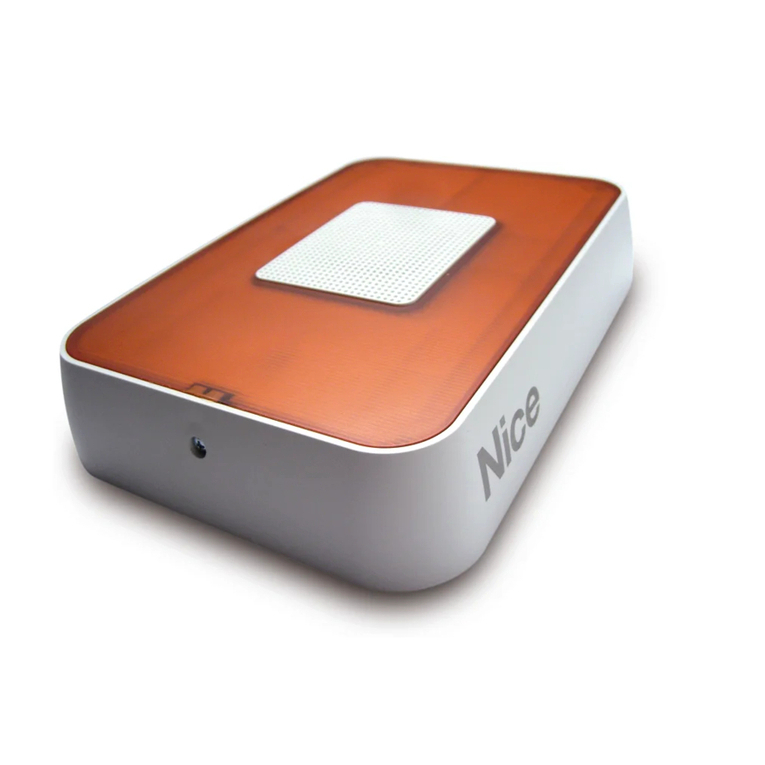
HSSOC Outdoors siren, wired to the control panel. Sound power 116 dB, with integrated flasher
HSSO1 Wireless outdoors siren, two-way and dual band. Sound power 116 dB, with integrated flasher and
voice card
HSSOC
HSSO1
HSSI
HSRT
HSMO
Keyboard
The keyboard can be used to control both the entire system and a limited area of it. It communicates with the control
panel and displays certain messages, such as: system status, alarms, faults, entrances open, etc.
The following models are available:
HSKPS Two-way, dual band radio keyboard, for controlling alarm and automation system control panels
HSSU1 Table mount for HSKPS keyboard HSKPS
HSSU1
EN50131
Grade 1
EN50131 Grade 1

8
q
p
o
m
l
i
h
g
f
e
d
c
b
a
r
4.1 - Setting up the system components for configuration
Since the system components communicate wirelessly, it is best to configure
the system first on the bench and only then locate and install the devices.
For control panels which also have electrical connections, proceed as
follows:
1) configure the wireless devices on the bench;
2) mount all devices;
3) make the electrical hookup.
To avoid errors, malfunctions and reception failures, proceed as follows:
This procedure checks the radio coverage of the devices before their
installation.
a) Place all products on the bench with their packaging open;
b) Fit the “voice guide” memory card into the control panel and, for GSM ver-
sions, the SIM card as well (see installation paragraph).
Warning: The SIM card's PIN must be cancelled, along with any messages,
contacts and other resident or saved information.
Caution: 3G SIM cards are not compatible.
c) Power up the control panel and program it in device acquisition mode;
d) Insert the batteries into the devices so that the control panel can acquire
them one by one;
e) Test the operation of the various devices;
f) Place the control panel in its intended location (do not mount it there yet);
g) Place the other devices in their intended positions (again, without mounting
them yet);
h) Check that every device has sufficiently wireless reception to operate (see
“Testing the control panel”);
In GSM models, check that there is sufficient reception:
i) Now install all devices in place;
l) If necessary, configure the advanced and detailed functions on the control
panel.
The following paragraphs describe the installation of the control panel (all mod-
els) and the electrical hookup of wired versions.
4.2 - Preliminary checks before installation and limitations on
use
Before proceeding with installation, check the condition of the product, suit-
ability of the selected model and conditions of the intended installation environ-
ment.
• Check that all conditions fall within the “limits of use” and “technical charac-
teristics”.
• Check that the installation location is compatible with the overall clearance
of the product.
• Check that the mounting surface is solid, so that the device is mounted
securely and is protected against impact.
• Install the control panel at least 1 m off the ground.
• the product may only be used with Nice Home Security system devices.
4.3 - Description of the control panel
All control panel models have a system memory card with voice guide (“l”
fig. 6A - 6B). The guide speaks the language of this manual; other language
versions are available.
The memory card is enclosed with this manual and must be inserted into the
control unit before starting the installation, and with it powered off (see par.
4.4.1).
During programming, the card stores the system parameters (excluding vocal
messages recorded by the installer or user) and can be transferred from one
control panel to another.
Some models of control panel (HSCU1GC and HSCU1G) are equipped with a
GSM phone dialler.
The SIM card must be inserted into the control unit before starting the instal-
lation, and with it powered off (see par. 4.4.1). The SIM card may be provided
by any cellular operator and with any contract (the system only uses the voice
and SMS services), but must be configured with PIN code = “1234” or set as
“access without PIN”: this can be done by inserting the SIM card in any GSM
phone.
Description of control panel:
Fig. 6A models HSCU1G and HSCU1 - Fig. 6B models HSCU1GC
and HSCU1C:
a- Display
b- Keyboard
c- Microphone
d- PSTN phone socket
e- Cable entrance hole
f- PC connection socket
g- Electrical terminal block (models HSCU1G and HSCU1GC)
h- Internal siren
i- Speaker
l- System memory card with voice guide
m- GSM SIM card (models HSCU1G and HSCU1GC)
n- Battery pack (models HSCU1G and HSCU1)
o- Backup battery (models HSCU1GC and HSCU1C)
p- Main power terminal clamp (models HSCU1GC and HSCU1C)
q- Power supply (models HSCU1GC and HSCU1C)
r- GSM antenna
INSTALLATION: control panel and accessories
4
n
m
l
i
h
f
d
c
b
a
r
Models HSCU1G and HSCU1
6A
Models HSCU1GC and HSCU1C
6B

9
4.4 - INSTALLATION: Control panel
(models HSCU1GC - HSCU1C and HSCU1G - HSCU1)
Caution - Before proceeding with the installation, read par. 4.1 - 4.2 - 4.3.
4.4.1 - INSTALLATION
01. Open the container, and remove the protective mask (fig. 7-A) and then
the cover (fig. 7-B);
02. Release the side hook to rotate the control panel's body (fig. 8);
03. Insert the provided memory card, taking care to insert it correctly into the
connector guides (fig. 9).
In control panel models HSCU1GC and HSCU1G (with GSM), insert
the SIM card (fig. 10).
04. Before securing the container, if you wish, you can activate the blade
proofing system on the rear tamper (fig. 11):
a) remove part “a” as shown and set it aside
b) remove part “b” as shown and discard it;
05. For models HSCU1GC and HSCU1C:set up the cable hole (fig. 12)
and run the power cables through it (fig. 13);
06. Restore the control panel body to its holder (fig. 14);
07. Mark the 3 mounting points on the wall as shown in fig. 15. If the blade
proofing system has been activated, mark point 4 for part “a” (fig. 15);
08. Drill the wall at the 3 marked points and insert the provided wall plugs (fig.
16). If the blade proofing system has been activated, drill point 4 and insert
the wall plug and part “a” you set aside previously (fig. 16);
09. Fix the control panel to the wall with the provided screws (fig. 17);
10. Electrical connections
8
9
SIM
10
x 4
7A 7B
• For models HSCU1GC and HSCU1C:
make the electrical connections and insert the backup battery with refer-
ence to chapter chapter 5.
• For models HSCU1G and HSCU1:
connect the battery (battery pack) as shown in fig. 18;
11. Close the container (fig. 19).
12. Now install the various devices and program the control panel (chapter 6).

10
13
12
CRACK
a
b
11
CRACK
CRACK
14
x 3
x 1 a
15

11
18
only models
HSCU1G and HSCU1
x 4
19
x 3
a
16
x 3
17

12
B
A
20
22
21
5.1 - Important warnings
• The mains power hookup must be done by a qualified electrician in
line with electrical equipment regulations.
• Install a 2-pole circuit breaker with contact gap of at least 3 mm, or an elec-
trical cable equipped with a plug for a standard socket.
• Run some tests with the battery alone (as applicable); make sure it is fully
charged.
• For compliance with EN 50131, the connections to supplementary sirens
(whether self-powered or not, and compliant with the standard) must be pro-
tected with a balanced TAMPER line, using the alarm inputs.
• The relay outputs must be used within the voltage and current limits given in
the figure.
• For compliance with EN5031, conventional detectors connected directly to
the control panel must be certified EN50131 grade 1 or higher, and operate
with balanced lines, hence resistors must be used as shown (only 3 wires of
adequate cross-section).
• The +OFF signal is positive when the control panel is disarmed, and blocks
any detectors/sirens equipped with the appropriate input.
• The fault input, if used, trips ANOMALY signals and the consequent phone
calls
• All unused inputs may be left disconnected (they need not be balanced),
unless they are incidentally closed, even temporarily. In this case the control
unit must be powered off and on again (line reset).
5.2 - Control panel connections (models HSCU1GC and
HSCU1C only)
Caution! – Before opening the control panel's enclosure, disconnect it
from the mains power supply.
01. To hook up the power cable, insert the ferrite cylinder as shown in fig. 20
and position it as shown in fig. 21;
Warnings:
- To facilitate the connections to the terminal clamps, depress the release
button.
- The wires must be secured by closing the terminal cover with its screw;
02. For the electrical connections to the terminal block, refer to Table 2;
03. To insert the backup battery (not included) refer to fig. 22;
04. Once the connections have been completed, close the internal cover and
only then close the circuit breaker or insert the mains plug.
5.3 - HSSOC siren connections
To connect the siren with the control panel, refer to Table 2 and gure 25A if
the inputs are set as N.C. or 25B if the inputs are set as balanced.
ELECTRICAL CONNECTIONS
5
SPK External speaker positive output (8 Ω). Intended for a supplementary speaker for the control panel's messages; see fig. 23
+ ALI Constant positive, for power to wired detectors; 12 V DC max. 500 mA; see fig. 24
+ OFF Positive when the control panel is disarmed, blocks wired sirens; see fig. 25
GND (all) Negative for all connections
+ SIR Positive when alarm is tripped, for supplementary sirens, 12 V DC max. 500 mA; see fig. 26
+ SAA Positive (14 V DC), for wired siren battery charger (not available if mains power is not present; see fig. 25
+ N Caution! – If 2 sirens are hooked up, you must fit 2 diodes to the clamp to prevent return signals.
Caution! – Never use this output for powering the sirens
KEY ON-OFF double balanced output for external key (closed = OFF); see fig. 27
IN1..IN6 Alarm inputs; see fig. 28
24H Double balanced fault input with EN50131 enabled (Y). With EN50131 disabled (N) it becomes an NC tamperproofing contact; see fig.
28 and 25A.
NC1-C1-NO1 R1 relay output, 12V max. 500mA (connect only to SELV circuits); see fig. 29
NC2-C2-NO2 R2 relay output, 12V max. 500mA (connect only to SELV circuits); see fig. 29
PHONE PSTN phone line connection; see fig. 6
PC PC connection (requires USB interface); see fig. 6
Note:
• The alarm and tamper inputs are enabled when first closed. If they are closed by mistake, they report an alarm. To reset the signal, enable/disable CON-
TROL PANEL TEST mode.
TABLE 2 - DESCRIPTION OF THE ELECTRICAL CONNECTIONS
OUTPUT DESCRIPTION

13
IN1 IN2+ALGND
GND +12V
IN3 IN4 IN5 IN6
22k 22k
IN1 IN2+ALGND IN3 IN4 IN5 IN6 24H
Tamper
Tamper
GND
+N
22k
22k
GNDKEY
GND SAA
NC1
C1 C2
NO1
R1 R2
NC2
NO2
RELAY
12 Vcc
LN
LINE
29
SPK GND
+-
23
SIRGND
+-
26
27
24
TAMPER ALARM
+OFF+AL
TAMP
HSSOC
HSSOC
HSCU1GC / HSCU1C
HSCU1GC / HSCU1C
+SAA+SIR
GNDGND IN6 24H GND
+N
+N TC
BATT
-+-
-
+
+
BATTERY
+OFF+AL
TAMP
+SAA+SIR
GNDGND IN6 24H GND
+N
+N
22k
TC
BATT
-+-
-
+
+
BATTERY
+OFF+AL
TAMP
HSSOC
HSSOC
HSCU1GC / HSCU1C
HSCU1GC / HSCU1C
+SAA+SIR
GNDGND IN6 24H GND
+N
+N TC
BATT
-+-
-
+
+
BATTERY
+OFF+AL
TAMP
+SAA+SIR
GNDGND IN6 24H GND
+N
+N
22k
TC
BATT
-+-
-
+
+
BATTERY

14
PROGRAMMING THE CONTROL PANEL
6
MEANING AND USE OF FUNCTION KEYS
OK
C
CONFIRM ESC
tDELETE
CHARACTER
QUIT p
q
SCROLL
MENU
REQUEST
TELE-SERVICE
REQUEST
SIM CREDIT
CONFIRM
ARMING
CONFIRM
DISARMING
DELETE
CANCEL
TABLE 3
SITUATION OF CONTROL PANEL WHEN FIRST POWERED UP
proceed by pressing OK then scroll through the options and confirm
FIRMWARE NUMBER
Code I-MEI SIM
SEARCH POSIT.
CONFIRM OK
VOCAL MESSAGES
CONFIRM OK
SMS
CONFIRM OK
KEYBOARD CODES
CONFIRM OK
ALARM GROUP A
CONFIRM OK
WIRED INPUT ISOLATION
CONFIRM OK
RELAY1 SETTINGS
CONFIRM OK
MEMORY
CONFIRM OK
REMOTE CONTROLS
CONFIRM OK
DETECTORS'ISOL.
CONFIRM OK
ENGLISH
CONFIRM OK
FACTORY CODE
0000
SET DATE
DD/MM/YY
USER CODE
1234
SET TIME
00.00
RELAY2 SETTINGS
CONFIRM OK
RADIO OUTPUT
CONFIRM OK
SEARCH NAME
CONFIRM OK
INSTALLER CODE
1111
CESA 200 BAUD 2
CONFIRM OK
CONTACT ID 18 1
CONFIRM OK
GPRS
CONFIRM OK
ALARM GROUP C
CONFIRM OK
24H PANIC AL.
CONFIRM OK
ALARM GROUP B
CONFIRM OK
24H ROBB. AL.
CONFIRM OK
WIRED INPUTS
CONFIRM OK
EXTERNAL KEY
CONFIRM OK
24H TECHN. AL.
CONFIRM OK
GSM TEL LINE
CONFIRM OK
ANTISCANNER
CONFIRM OK
SUPERVISION
CONFIRM OK
EXIT TIME
CONFIRM OK
BACKLIGHTING
CONFIRM OK
VOLUME
CONFIRM OK
AUT.SUMMER H
CONFIRM OK
FORCED ARMING
CONFIRM OK
WIRED INPUTS
CONFIRM OK
ARMING BLOCK
CONFIRM OK
DIG. PROTOCOLS
CONFIRM OK
MESSAGES
CONFIRM OK
PHONE BOOK
CONFIRM OK
SETTINGS
CONFIRM OK
EXTRAS
CONFIRM OK
PC REMOTE MANAG
CONFIRM OK
MAINS FAILURE
CONFIRM OK
PERIODIC CALL
CONFIRM OK
TIME AND DATE
CONFIRM OK
SIM VALIDITY
CONFIRM OK
INSTAL.NUMBER
CONFIRM OK
ACCESS CODE
CONFIRM OK
INSTALLER NAME
CONFIRM OK
SWITCHBOARD
CONFIRM OK
INSTALLER CODE
CONFIRM OK
CUST.SERV.NUMB.
CONFIRM OK
CALL CUST.SERV.
CONFIRM OK
PERSONAL DATA
CONFIRM OK
SET EN50131
CONFIRM OK
FW VERSION
CONFIRM OK
SYSTEM RESET
CONFIRM OK
6.1 - PROGRAMMING PROCEDURE
We advise programming the control panel on the bench, with the various wireless
devices at hand, except for the sirens. Then place the devices in their final posi-
tions, after checking the radio coverage. You must then open the devices via their
battery compartments. If the equipment is wired, it can be programmed later. We
recommend following the programming procedure outlined in this manual.
6.2 - PROGRAMMING MESSAGES
To record vocal messages, hold down OK and talk into the control panel's
microphone, making sure to speak clearly and distinctly. During the recording,
the seconds available for other messages will display and count down, starting
from 240 seconds: it is essential that the messages recorded be short, since
you may need to record multiple messages (see below).
A

15
6.2.1 - Example text: CAUTION, ALARM AT CASA ROSSI, VIA BIANCHI 1,
TURIN (pause) DETECTOR . . . the message is automatically completed
with the label (i.e. position) of the detector which generated the alarm.
Release the button to stop recording and listen to the message; you
can either delete it (CANC) or accept it (ESC). Once you have accepted
the recorded message, the display prompts for you to associate it to the
event, as follows:
1) GROUP AL. A,B,C: intrusion alarm message generated by detectors
programmed for the groups in question.
2) TAMPERING AL.: this alarm message is always active, and is gener-
ated when the system devices are tampered with
3) 24H PANIC AL.: manual alarm message, generated by pressing
remote control key for instance.
4) 24H ROBBERY: manual alarm message, we recommend using a
dedicated remote control for this.
5) 24H TECHNOL.: alarm message generated by a technical detector
(smoke, flooding, gas, etc.)
6) LOW BATTERY: identified alarm message, generated by any system
component.
6.2.2 - POSSIBLE VARIATIONS OF MESSAGES
You can use keys pqto vary the events (you must also record a suit-
able message) among the above options or one of the following: 6 mes-
sages are available, so that you must discard one of the above ones if
you choose one of those given below.
ALARM GROUP A (only): delete B and C by pressing 2 and 3 when
programming message 1
ALARM GROUP B (only): delete A and C by pressing 1 and 3 when
programming message 1
ALARM GROUP C (only): delete A and B by pressing 1 and 2 when
programming message 1
MAINS FAILURE (models HSCU1GC and HSCU1C): transmit message
after set power failure timeout (SETTINGS)
PERIODIC CALL : call transmitted every 1-25 hours (SETTINGS)
TEMPERATURE: transmit message when the control panel temperature
is higher than 70°C or lower than 5°C
ANOMALY (a WARNING displays on the control panel): transmits a
generic message, including signal to the 24H input, mains failure, low
battery charge, antiscanner, supervision, temperature (< -10°C or >
55°C), PSTN phone line fault.
FREE FIELDS – SPECIFIC MESSAGE: “ _ , “ displays
The following events are available: ALARM = alarm; SUPERV = super-
vision alarm; SCAN = radio disturbance alarm; ARM = control panel
armed; DISARM = control panel disarmed; D.OPEN = door left open;
END AL = door closed again; ARM A, ARM B, ARM = arm group in
question; NO EVENT: confirming this option disables calls to the associ-
ated numbers.
To program the function, enter the event in the first part of the display,
exactly as indicated above in uppercase (e.g.: enter ARM and confirm
OK), then enter the label of the device generating the event in the sec-
ond part (see EXTRAS) and confirm OK: for the control panel, enter
C.PANEL.
6.2.3 - VOCAL MESSAGE 7 (see 9.8.1)
If there are no domotics actuators, it is sufficient to record how to
operate the control panel remotely: once the command is given, the
response is in clear.
- to check the control panel's status (armed/disarmed) press zero #
- to arm the control panel completely, press zero ✱1 #
- to arm only groups A+B press zero ✱2 #
- to disarm, press zero ✱zero #
If any remote domotics actuators are present (lights, electrical appli-
ances) you must record how to execute the commands for the actua-
tions in question: see 9.8.4.
Caution! If these messages are not recorded, the control panel will not
respond to PSTN calls, while if equipped with always active GSM it will
respond (model HSCU1GC).
6.2.4 - SMS – TEXT MESSAGES (GSM models only)
In the same sequence and using the same association procedure, enter
the user messages: e.g. ALARM ROSSI TURIN (max. 24 characters).
6.2.5 - RESIDENT TECHNICAL SMS's
These messages are resident and need only be associated to the
phone number.
1 = low battery control panel: important! The system is close to failure!
2 = low battery peripheral: important! One or more detectors may soon
stop working (in days)!
3 = supervision failure or scanner: check the event log on re-entry
4 = control panel armed: the message is only sent in response to
remote arming by phone
5 = control panel disarmed: the message is only sent in response to
remote disarming by phone
6 = 230V mains failure - the message is sent after the set timeout (SET-
TINGS)
7 = no GSM reception for more than 15 min.: the message is sent when
GSM coverage is restored
8 = no successful call on PSTN line: check for phone line failure (land-
line)
9 = periodic call to indicate that the control panel is present: sent every
set number of hours/days (SETTINGS)
10 = SIM validity warning message: program (SETTINGS) a new validity
date when using a prepaid SIM card
11 = 230V mains power restoration: automatic message following SMS 6
6.2.6 - EVENT MESSAGES SENT BY THE CONTROL PANEL
Control panels without voice guide require the messages they are to
send to be recorded.
If the voice guide is standard supply, these messages are pre-recorded,
and the menu in question is not available:
1 Arming enables the complete system
2 Partial arming enables part of the system (as selected)
3 Disarming disables the complete system
4 Door open indicates that a door/window with open detec
tor has been left open
5 External alarm not available in this configuration
6 Pre-alarm sound alarm which precedes the alarm itself,
during the entry delay set on the control panel
7 Tamper indicates that a disarmed part of the control
panel has been tampered with
8 New event indicates that an event has occurred since the
system was last armed (see event log).
6.2.7 - PROGRAMMING PHONE BOOK – MAX 63 NUMBERS
When necessary, the control panel calls the numbers in the phone
book to send them vocal and SMS messages. The numbers must be
programmed and associated with the various messages sent when an
event occurs, so that each call must be associated with the appropriate
messages (see 9.7.2).
Caution! Remaining credit request key: position 64 of the phone book
is reserved for the number provided by the cellular operator for this
operation; the response is a vocal message. GSM request: the cellu-
lar operator's number must be programmed 123456 # (asterisk first
and hash at the end): pressing the key on the control panel sends the
remaining credit to the first number in the phone book via SMS, which
must be a cellular phone (in Italy, the number of the three Italian opera-
tors, TIM, WIND and Vodafone, is entered automatically). You can also
obtain the remaining credit by sending an SMS to the control panel with
a single question mark: the response is sent to the phone used to send
the request.
Caution! NICE is not responsible for changes made by the cellular
operator which may make any of the functions, set up with the informa-
tion available at the time of design of the unit itself, unusable.
The PHONE BOOK menu has three variants:
MEMORY: for inserting new numbers and associating them with mes-
sages
SEARCH NAME: for finding a number by name and changing its entry
– a user-friendly approach to programming
SEARCH POSIT.: for finding a number by its position in the contacts
and changing its entry – a user-friendly approach to programming
MEMORY: you are prompted to enter the name and number of the
person to call: when you confirm the operation, the text MEMORIZZA-
TO (MEMORISED) displays. Press OK to continue: enter the numbers
of the messages you wish to associate to this number, both vocal, SMS
and technical SMS.
Caution! If a number has no messages associated with it, it is not
called.
DIRECT ACCESS N (GSM models only): by changing N to Y (yes) by
pressing the key, the central will recognise the number of the caller via
GSM and will thus not request the code, so that all functions are avail-
able to the caller.
Caution! Phone line check: according to the standard, the control cen-
tre checks the PSTN line and only makes the call if the line is unen-
gaged and operating correctly. If the dialling tone is disturbed the check
may be cancelled by entering ✱(press p) before the number during
programming.
Caution! Pause between numbers: if you wish to leave a pause
between numbers as they are dialled, enter (pause) between them.
6.2.8 - EXTRAS – PROGRAMMING THE PERIPHERALS
This menu is used to program the peripheral equipment on the control
panel, grouped by type as explained in the “First power up” table. Each
type of peripheral is flexibly programmable to enable it to suit the needs
of each installation, as required by the user.
6.2.9 - REMOTE CONTROLS: you can program up to 32 HSTX4, HSTX8
portable transmitters (over 1 million rolling code combinations) for arm-
ing/disarming the control panel and activating specific functions (1 key
available). Enter the menu; the message “REM.CONTROL 1” displays:
confirm. Each remote can control groups A, B and C, both to arm and
disarm them, or part of them as desired: press the numbers 1 to 6 to
disable operations in a single group. The excluded groups will disap-
pear, and the remote will only be able to control the remaining groups
and their functions.
Program the remote control as requested and wait for the unit to buzz in
confirmation. Press OK to enter the name of the remote user and then
register it locally: as a result, any message or memorisation of manoeu-
vres involving that remote will be recognisable by that name.
6.2.10 - KEYBOARD CODES (up to 32 available): these are groups of 5 dig-
its for arming/disarming the control panel with its on-board or a remote

16
keyboard. When you enter the menu Code 1 displays: confirm and pro-
ceed as for the remote controls, entering a mnemonic code for its user.
UNDER THREAT: see 9.6.3; to enable this function, change N to Y (p),
then proceed as above.
6.2.11 - ALARM GROUP (A,B,C): 3 groups of intrusion detectors which are
armed/disarmed together, to enable partial use of the alarm system.
The installer will decide on the best solution together with the user.
The control panels accepts up to 99 detectors, but note that self-pro-
tection, battery check, keyboard supervision and sirens each occupy
one location per detector, hence these devices must be included and
programmed among the available 99: hey do not generate intrusion
alarms, but only tampering alarms or messages to control the said
functions. When you enter the menu, ALARM GROUP A – OUTDOOR
ALARM displays: this function is not compliant with the standard. Press
qto obtain the first free location for detectors/sensors (SENSOR A01).
Program the entry delay (key 1, then enter the time from 1 to 45 sec-
onds) or the AND function (see below). If you do not require a delay
or AND, simply confirm until INSERT BATTERY displays: when you fit
the battery into the detector, you will hear a confirming beep. Caution!
Read the detector instructions, since there may be particular functions
which require programming first. Then enter the label, which identifies
the position of the device ( 9 characters, like MN DOOR for the main
door) and record the vocal message.
Caution! If the alarm message has been recorded as explained in
6.2.1, it will end with . . .DETECTOR . . . so that you need only record
MAIN DOOR, without repeating DETECTOR.
ALARM GROUPS B and C: proceed as for group A
6.2.12 - AND function: you can use the AND function to program 2 sen-
sors/detectors to protect a single room: the alarm is only generated if
one detector trips and the second one trips as well within 30 seconds.
By locating the two detectors properly, this can significantly reduce the
potential for false alarms in difficult areas (with small birds, strong drafts
and other phenomena to which the detector is sensitive). Different
types of detectors may used in an AND configuration. Confirm the AND
option (this is not possible if a delay has been entered) and program the
two devices one after the other.
6.2.13 - 24 HOUR ALARM GROUPS
24H PANIC (uncertified function): you can program a free key of a
remote control (or a dedicated remote control, or the HSDID11 con-
nected to a button) for immediate siren activation: the procedure is simi-
lar to the above, but you must hold the button down for 10 seconds
when prompted to do so by the control panel.
24H ROBBERY: you can send silent calls (medical as well) in the same
way as above.
24H TECHNOL. (uncertified function): the Nice range includes
flooding and smoke detectors. You can use an HSDID11 detector to
integrate any other commercially available detector. These devices
can be programmed to the group in the same way as other detectors
(6.2.11).
6.2.14 - WIRED CONNECTIONS (HSCU1GC and HSCU1C only):
EXTERNAL KEY: you can connect an external key to the control panel
(see fig. 27) via a balanced line. For compliance with the standard, it
must be protected and certified at least grade 1. The programming pro-
cedure is similar to that used for remote controls.
WIRED INPUTS: the six wired inputs (double balanced – see diagram
fig. 24) are divided as follows: A+1+2; B+3+4; C+5+6, but they can be
combined in different ways by pressing keys 1-2-3 when the group is
displayed on the control unit. They are programmed in a similar way to
wireless groups, but the AND function is not available.
6.2.15 - SETTINGS
This menu is used to configure the operational parameters and other set-
tings, some of which are accessible to the user (see par. 9), as follows.
Caution! For conformity with EN 50131 . . certain functions are mandato-
ry and limited as indicated, and non-compliant settings are not accepted.
Caution! Make sure to confirm all settings as you make them.
6.2.16 - DETECTORS'ISOL.:enter the menu, select the detector/sensor in
service (INCLUD), and put it out of service (EXCLUD) by pressing OK.
Repeat to return it to service.
6.2.17 - WIRED INP.ISOL: enter the menu, select the detector/sensor in
service (INCLUD), and put it out of service (EXCLUD) by pressing OK.
Repeat to return it to service.
6.2.18 - RELAY1 SETTINGS: the relay may be used for controlling electrical
loads, within the indicated limits (fig. 29) and in combination with diverse
activities: the factory setting for R1 is ON-OFF, bi-stable switching (tog-
gling) which changes following an ON command and returns to standby
with an OFF via phone. If combined with the internal clock, phone-oper-
ated toggling has priority over clocked toggling. R1 can also be used in
other ways, as follows:
IMPULSIVE: switches for 0 to 999 seconds on receiving an internal
clock or phone command.
GENERAL ALARM: switches for the set time for alarms of any type,
excluding antiscanner alarms.
TAMPERING AL.: switches for 3 minutes in case of tamper alarm
(24H PANIC/ROBBERY/TECH. AL.): switches for 15 seconds when a
Panic/Burglary/Technical alarm is generated
ANOMALY: switches for 15 seconds when the batteries are low (con-
trol panel or detector), supervision failure, radio disturbance with control
panel armed (antiscanner), no GSM network (HSCU1GC).
ARM./DISARM.: switches when armed and returns to standby when
disarmed (used to connect an on-off led, for example)
DELAY: switches during the entry delay set for one or more detectors
(entry time).
6.2.19 - RELAY2 SETTINGS: the relay may be used for controlling electri-
cal loads, within the indicated limits (fig. 29) and in combination with
diverse activities: the factory setting for R2 is GENERAL ALARM, which
switches for 3 minutes when an alarm is generated. This relay cannot
be activated by the clock, otherwise it can be used just like relay R1.
6.2.20 - RADIO OUTPUT (uncertified function): you can operate local com-
mand functions by calling the control panel with your phone. The con-
trol panels have 16 wireless transmissions for activating HSTT2L and
HSTT2N receivers, which can switch lights on and off and control auto-
mation equipment and electrical loads. To operate under the control
panel's control, they must memorize one of the above RADIO OUTPUT:
confirm the output as pulse or change to on/off (pq), then prepare the
receiver and press OK to program it (see receiver instructions).
Caution! These functions require you to record guide messages (6.2.3)
to aid the user in operating them by phone.
6.2.21 - GSM-PSTN LINE (HSCU1GC and HSCU1G only): select the prior-
ity mode for outgoing calls (pq) . If the priority option fails, the other
method is automatically selected.
6.2.22 - MAINS FAILURE (HSCU1GC and HSCU1C only): This function is
always active if EN50131 is set to Y (6.2.36). With EN50131 disabled,
the mains failure function can be confirmed (Y) or disabled (N). Follow
the voice prompts to receive an SMS after the set time (1 to 60 min-
utes).
6.2.23 - PERIODIC CALL: This function is always active if EN50131 is set to Y
(6.2.36). With EN50131 disabled, the periodic call can be confirmed (Y)
or disabled (N). Enter the transmission interval (per the standard, 1 to 25
hours), and then the count start hour.
6.2.24 - SIM VALIDITY: Activate the function by setting N (no) to Y (yes) by
pressing pq, then enter the SIM validity in months, leaving at least
one month margin.
6.2.25 - TIME AND DATE: updating the internal clock and date is important
for the event log. Internal clock - precision: up to 2 seconds a day,
which can be corrected during scheduled maintenance, as provided
by EN 50131.
6.2.26 - TEL. EXCHANGE: Use pqto select whether to enable the tel-
ephone exchange function (Y) and set the digit for outside calls.
N.B.: - If the EN50131 function is enabled, this menu is only visible if the
phone line is detected.
6.2.27 - INSTALLER CODE: used to display/change the code. If you lose
this code, you must open the control panel, thus tripping the tamper
alarm, disconnect the battery and mains power, power on again after a
few seconds, and enter programming mode with the factory code. This
does not lose programmed data.
6.2.28 - ANTISCANNER: This function is always active if EN50131 is set to Y
(6.2.36). With EN50131 disabled, the Antiscanner function can be con-
firmed (Y) or disabled (N). The control panel monitors radio signals and
reports any which are disturbing its operation. You can set the negligible
disturbance time in seconds (1-60), after which the control panel's siren
sounds and current is sent to the SIR terminal (models HSCU1GC and
HSCU1C only) for 30 seconds. If you wish, you can associate a vocal
message or SMS or one of the relays with this function.
6.2.29 - SUPERVISION: This function is always active if EN50131 is set to
Y (6.2.36). With EN50131 disabled supervision can be confirmed (Y)
or disabled (N). Supervision is the good working order signal which all
peripherals transmit every 28 minutes or so: failure of any peripheral to
transmit this signal generates an ANOMALY warning when the system
is armed/disarmed. If even just one such signal is lacking during the
60 minutes before the system is armed, the system will not be armed.
If you wish, you can associate a vocal message or SMS or one of the
relays with this function.
6.2.30 - EXIT TIME: Caution! Too short a setting does not allow for service
communications which occur during this period. The standard allows
for settings of 1 to 99 seconds.
6.2.31 - AUT.SUMMER H: this function is normally enabled, and can be disa-
bled by pressing # where daylight saving time is not in force.
6.2.32 - BACKLIGHTING: activate the function (HSCU1GC and HSCU1C
only). The display can be continuously backlit by switching from N (no)
to Y (yes) with pq. Caution! If mains power is not available, the
backlighting goes out.
Models HSCU1G and HSCU1: the units are factory set for backlighting
to go out after 60 seconds idle time.
6.2.33 - VOLUME: the audio volume can be set with pq.
Caution: With the volume set to 0 the beeps are also excluded.
6.2.34 - FORCED ARMING: to arm the control panel at a set time, enable
this function by switching from N (no) to Y (yes) with pq. The control
panel can be partially or totally armed at set times (see 3.6.4). Disarming

17
is always manual.
6.2.35 - ARMING BLOCK: This function is always active if EN50131 is set to
Y (6.2.36). With EN50131 disabled, the arming block function can be
confirmed (Y) or disabled (N).
Note: refer to par. 9.6.1.
6.2.36 - Compliant EN50131: Switch to Y (yes) with pqto set all parameters
compliant with EN50131. N (no), which is the default setting, enables
you to use functions and parameters not envisaged by EN50131.
Caution: With this parameter set to N (no), the system excludes com-
pliance with EN50131.
6.2.37 - FW VERSION: displays the control panel's firmware version, which is
required for upgrades.
6.2.38 - SYSTEM RESET: confirming (OK) the prompt SYSTEM RESET?
removes all programmed settings and the event log. This operation
cannot be undone - be sure of what you are doing.
6.3 - DIG. PROTOCOLS
The control panels have two types of digital protocol among those most com-
monly used by private security companies, with the option of transmission
to 2+2 PSTN numbers, optionally belonging to different security companies.
Alarms can also be transmitted by GPRS (IP). The menu allows you to choose
the protocol or mode, as follows:
6.3.1 - CONTACT ID / CESA 200 BAUD: enter the client ID, primary and sec-
ondary phone numbers (if not applicable, press OK ) for transmission,
select direct or inverse mode (pq) and then enable (N/Y) (pq, the
OK ) the messages to be transmitted one at a time, as agreed with the
receiving control panel.
Advanced programming: in the CODEV field, enter 1 to 4 further spe-
cific events for transmission. You must enter the type of event in the first
part (e.g. ALL) and the peripheral's label or position in the second part
(e.g. A03 - for the control panel, enter CENTRALE (CONTROL PANEL)),
the control panel will now propose a code for transmission.
For the CONTACT ID protocol, you can modify the proposed code, but
the code is fixed for the CESA 200 protocol (96 for CODEV1, 97 for
CODEV2, 98 for CODEV3, 99 for CODEV4).
Example CONTACT ID:
CODEV1 1 130 01 003
ALARM , A03
After you enter the event ALL ( OK ), the position
A03 ( OK ), the first line proposes the code to asso-
ciate with the event for transmission with the CON-
TACT ID protocol; confirm with OK or modify the
code t).
Advanced programming also allows you to enter the detector label rather than
its position; if you have given detector A03 the label “KITCHEN”, then you can
set:
CODEV1 1 130 01 003
ALARM ,
KITCHEN
After you enter the event ALL ( OK ), the label
“KITCHEN” ( OK ), the first line proposes the code
to associate with the event for transmission with
the CONTACT ID protocol; confirm with OK or
modify the code (t).
Example CESA 200 BAUD:
CODEV1 96
ALARM , A03
After you enter the event ALL ( OK ), the position
A03 ( OK ), the first line proposes the code to asso-
ciate with the event for transmission with the CESA
200 protocol; confirm with OK.
Only events listed below are available, and the peripherals must have been
already memorized; make sure your entries are correct otherwise the control
panel will not be able to make the right associations.
EVENT MEANING PERIPHERAL MEANING
ALARM Alarm A01 – A99 Group A detectors
END AL End of alarm B01 – B99 Group B detectors
C01 – C99 Group C detectors
TAMPER Tamper P01 – P99 24H PANIC AL.
group detectors
SUPERV No supervision R01 – R99 24H ROBB. AL.
group detectors
SCAN Radio distur-
bance detected
T01 – T99 24H TECHN. AL
group detectors
BATT Battery low WIR A1 – A2 Group A wired
detectors
D.OPEN Door open dur-
ing arming
WIR B1 – B2 Group B wired
detectors
ARM Full arming WIR C1 – C2 Group C wired
detectors
ARM A Arm group A WIR A Group A wired
detector tamper
ARM B Arm group B WIR B Group B wired
detector tamper
ARM C Arm group C WIR C Group C wired
detector tamper
ARM AB Arm group AB TEL01 – TEL32 Remote controls
ARM AC Arm group AC COD01 –
COD32
Keyboard codes
ARM BC Arm group BC WIR KEY Key input
DISARM Disarming CONTROL
PANEL
Control panel
6.3.2 - DIGITAL TRANSMISSION TEST
With the control panel disarmed you can send a TEST event to a secu-
rity company, as described in 9.5.1.1 – 9.5.1.2: conform TEST COMBI-
NATORE (DIALLER TEST), enter the phone number and select the type
of message to transmit (CONTACT ID or CESA 200), confirming the
displayed prompts.
To run the dialler TEST, you must have programmed the digital proto-
col you intend to use: for CONTACT ID the transmitted code is 602,
whereas for CESA it is 90.
6.3.3 - TABLE OF DIGITAL PROTOCOL CODES
EVENT CONTACT ID CESA 200 CESA 200
GROUP A ALARM 1 130 01 001/099 1 14/22 detectors 01 to 09 1 23 detectors 10 to 99
END OF GROUP A ALARM 3 130 01 001/099 2 14/22 detectors 01 to 09 2 23 detectors 10 to 99
GROUP A WIRED ALARM 1 130 01 101/102 1 24/25 detectors 01 and 02
END OF GROUP A WIRED ALARM 3 130 01 101/102 2 24/25 detectors 01 and 02
GROUP B ALARM 1 130 02 001/099 1 26/34 detectors 01 to 09 1 35 detectors 10 to 99
END OF GROUP B ALARM 3 130 02 001/099 2 26/34 detectors 01 to 09 2 35 detectors 10 to 99
GROUP B WIRED ALARM 1 130 02 103/104 1 36/37 detectors 01 and 02
END OF GROUP B WIRED ALARM 3 130 02 103/104 2 36/37 detectors 01 and 02
GROUP C ALARM 1 130 03 001/099 1 38/46 detectors 01 to 09 1 47 detectors 10 to 99
END OF GROUP C ALARM 3 130 03 001/099 2 38/46 detectors 01 to 09 2 47 detectors 10 to 99
GROUP C WIRED ALARM 1 130 03 105/106 1 48/49 detectors 01 and 02
END OF GROUP C WIRED ALARM 3 130 03 105/106 2 48/49 detectors 01 and 02
24H PANIC AL. 1 123 04 001/099 1 55/58 detectors 01 to 04 1 59 detectors 05 to 99
24H ROBB. AL. 1 122 05 001/099 1 50/53 detectors 01 to 04 1 54 detectors 05 to 99
24H TECHN. AL. 1 150 06 001/099 1 61/88 detectors 01 to 28 1 89 detectors 29 to 99
CONTROL PANEL TAMPER 1 137 00 000 1 94
GROUP A TAMPER 1 137 01 001/099 1 12
GROUP A WIRED TAMPER 1 137 01 000 1 12
GROUP B TAMPER 1 137 02 001/099 1 12
GROUP B WIRED TAMPER 1 137 02 000 1 12
GROUP C TAMPER 1 137 03 001/099 1 12

18
GROUP C WIRED TAMPER 1 137 03 000 1 12
24H PANIC AL. GROUP TAMPER 1 137 04 001/099 1 12
24H ROBB. AL. GROUP TAMPER 1 137 05 001/009 1 12
24H TECHN. AL. GROUP TAMPER 1 137 06 001/009 1 12
ARMING VIA USER CODE 1 401 00 000 1 60
DISARMING VIA USER CODE 3 401 00 000 2 60
REMOTE CONTROLS ACTIVATION 1 401 00 001/032 1 60
REMOTE CONTROLS DEACTIVATION 3 401 00 001/032 2 60
ACTIVATION CODES 1 401 00 033/064 1 60
DEACTIVATION CODES 3 401 00 033/064 2 60
ARMING VIA EXTERNAL KEY 1 409 00 000 1 60
DISARMING VIA EXTERNAL KEY 3 409 00 000 2 60
ARMING VIA REMOTE PHONE 1 407 00 000 1 60
DISARMING VIA REMOTE PHONE 3 407 00 000 2 60
CONTROL PANEL BATTERY 1 302 00 000 1 91
RESTORE CONTROL PANEL BATTERY 3 302 00 000 2 91
PERIPHERAL BATTERY 1 384 01/06 001/099 1 13
RESTORE PERIPHERAL BATTERY 3 384 01/06 001/099 2 13
MAINS FAILURE 1 301 00 000 1 92
MAINS RESTORATION 3 301 00 000 2 92
PERIODIC CALL 1 602 00 000 1 90
NO SUPERVISION GROUP A, B, C, T 1 381 00 000 1 11
SCANNER 1 344 00 000 1 95
OPEN DURING GROUP A, B, C ARMING 1 371 01/03 001/099 NOT USED
6.3.3 - GPRS: fill in the fields as follows:
INTERNET DATA
APN: request the GPRS data connection APN from your cellular operator.
IP: not required at this time for TIM, WIND and VODAFONE users. If a different SIM is used, request this setting from your cellular operator.
USER: not required at this time for TIM, WIND and VODAFONE users. If a different SIM is used, request this setting from your cellular operator.
PSW: not required at this time for TIM, WIND and VODAFONE users. If a different SIM is used, request this setting from your cellular operator.
GPRS 1-2 (first and second connection option – same procedure) – see SECURITY COMPANY DATA menu
USERNAME enter the 4 digit number provided by the security company
TCP / UDP MODE select the mode (pq) and confirm (OK)
IP ADDRESS enter the IP of the security company switchboard
IP PORT enter the IP PORT of the security company switchboard
BACK-UP SMS NUM enter a number of the security company switchboard to which SMS's can be sent if transmission fails
PERIODIC CHECK enter the interval (in minutes) between check transmissions
SIA 1-2 (first and second connection option – same procedure) – see MON.STAT.DATA menu
USERNAME enter the 4 digit number provided by the security company
TCP / UDP MODE select the mode (pq) and confirm (OK)
IP ADDRESS enter the IP of the security company switchboard
IP PORT enter the IP PORT of the security company switchboard
PERIODIC CHECK enter the interval (in minutes) between check transmissions
EVENTS menu see 6.3.1 and enable the events you require
6.3.4 - PC REMOTE MANAG
(advanced programming, without voice guide)
The control panel has a tele service feature. For this function, the control panel must be connected to the PSTN line and
the customer service must be equipped with an HSMO phone modem and
software for PC Tele Service.
The tele service feature must however be expressly activated by the user by pressing .
For the settings required for tele service, see the HSMO modem's manual.
Other manuals for HSCU1
1
Table of contents
Other Nice Security System manuals

Nice
Nice HSSO1 Technical specifications

Nice
Nice HSDIW01 User manual

Nice
Nice HSDIW01 User manual

Nice
Nice HSSOC User manual

Nice
Nice FE Series User manual

Nice
Nice HSSOC User manual

Nice
Nice numera 2GIG 2GIG-PHB1-345 User manual

Nice
Nice Linear IV200 Series User manual

Nice
Nice HSSO User manual

Nice
Nice HSMO - HSA1 User manual