Crystal Water CW-A1004 User manual

CRYSTAL WATER
Installation Guide
CW-A1004 Slimline Reverse Osmosis System

Contents
SECTION
PAGE
Features
1
Specifications
2
Water Treatment Process and Electrical Diagram
3
Product and Accessories
4
Functional Schematic Diagram
5
Installation Instructions
6
First Use Instructions
8
Cartridge Replacement
9
Troubleshooting
10
Precautions for Use
11
Commissioning Checklist
12
Warnings
13

1 | P a g e
Features
•Easily Installed with the use of an Arco Conekta Mini Stop Water Diverter
•Can be easily connected to an existing Flick Mixer Tap (other fittings may be
required) or the Standard Tap provided.
•Purifies Standard Municipal Water Supplies
•Automatically Shuts off Water when a Leak is Detected.
•Runs 110-240V AC Power (Power Supply included)
•Automatically Flushes system
•Built in TDS Meter
•Built in Independent Filter Monitors

2 | P a g e
Specifications
Slimline Reverse Osmosis System
•Feed Water Quality
oMunicipal Tap Water
•Voltage and Frequency
o100-240V, 50/60 Hz
•Power Input
o96 Watts
•Purified Water Flow
o1.2 Lt per minute
•Feed Water Temperature
o5-45 ºC
•Feed Water TDS
o~250 ppm
•Feed Water Chlorine Level
o~0.2ppm
•Rejection:
o90-99%
•Feed Water Pressure
o100-400 kpa
•Electric Shock Resistance
oType II

3 | P a g e
Water Treatment Process and Electrical Diagram
Technological Process
Electrical Diagram
4 | P a g e
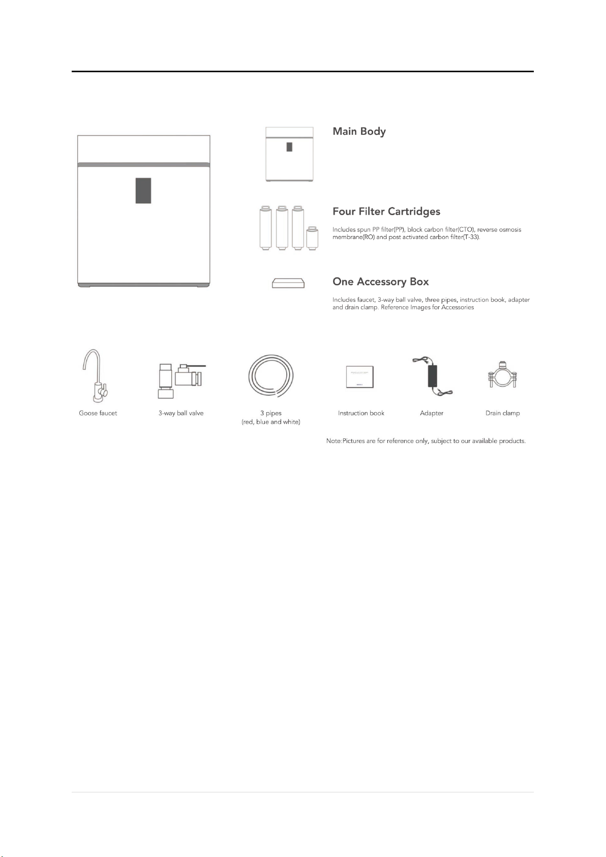
Product and Accessories

5 | P a g e
Functional Schematic Diagram

6 | P a g e
Installation Instructions
1. Attach Inlet Water Supply
a. Locate and Close the Cold-Water Angle Stop Valve Under your kitchen sink. Open
the Cold-Water line one your existing Tap to release the water pressure.
b. Unscrew and disconnect the braided tubing on the threaded end of the Angle
Stop Valve.
c. Attach the Solenoid Valve to the Arco Mini Stop Valve. Attach the ½” Push-fit
Fitting to the End of the Stop Valve.
d. Attach the Arco Conekta Mini Stop Valve to the existing Cold-Water Angle Stop
Valve.
e. Attach the Braided tubing to the top of the Arco Conekta Mini Stop Valve.
f. Close the Side Valve on the Arco Conekta Mini Stop Valve and open the Cold-
Water Angle Stop Valve to return water service to the Kitchen Sink. Check for
Leaks.
g. Measure length of tubing needed to connect the Diverted water to the Inlet of the
System. Allow adequate tubing to avoid sharp turns.
h. Cut at a 90-Degree angle using a sharp knife.
i. Attach one end of the tubing to the Water Diverter Fitting.
j. Measure approximately 30-50mm away from the Water Diverter Fitting along the
tubing.
k. Cut at a 90-Degree angle using a sharp knife.
l. Attach the Water Diverter Tube to the Bottom of the PLV Check Valve and the
Remaining Tube to bother the outlet of the PLV Check Valve and the Inlet of the
System.
2. Install Supplied Tap
a. Place Cover Plate on top of the counter for the placement of the Tap.
b. Mark on the counter for drilling the hole for the tap. Ensure the is adequate room
both on top and underneath the counter/sink top for the locking nut, round plate
and push fit fitting installation.
c. Drill hole into the counter/sink top for the shaft of the Tap to go through. Clean
any potential burrs or knicks around the hole.
d. Place the small rubber Washer, Chrome Cover plate and large Rubber Washer (in
that order) on the shaft of the faucet. Insert shaft into the hole on the
counter/sink top.
e. Place Round Plastic Plate and Locking Washer on under the counter/sink side of
the faucet shaft. Tighten with the Locking Nut supplied on the shaft and ensure
the tap handle is pointing in the desired direction.
f. Attach the remaining Push-fit fitting onto the bottom of the shaft of the tap.
Tighten to ensure the internal seal is on the base of the tap.

7 | P a g e
3. Attach Filtered Water to Sink Tap
Measure length of tubing needed to connect the Outlet of the Filter Head to the Tap
connector fitting. Cut and insert each end of the tubing into the fittings.
4. Install the Drain Clamp
a. Select a location for the drain clamp above the “S”Trap but not more than
40mm above the normal water level or the best location is on the transfer
pipe between twin bowl sinks if you have one.
b. Position the drain outlet clamp on the drainpipe. Allow adequate space for
drilling. Tighten clamp with the “Tightening Screw.”
c. Using the opening in the drain outlet clamp, drill a ¼” hole in the drainpipe.
d. Clean debris from the clamp.
e. Attach the Red pipe, to the Drain Outlet on the System and to the Drain Clamp.
Allow for adequate tubing to prevent kinks.
NOTE: Locate the drain connection away from the garbage disposal to prevent potential
contamination and system fouling.

8 | P a g e
First Use Instructions
1.
a. Connect RO System with the Power Adapter.
b. Connect to power outlet in your wall.
c. Check the power light indicator on the power supply is illuminated.
d. Once the system is powered on, a buzzer will ring 3 TIMES.
e. Machine will flush for 90 seconds and the flushing icon on the system will
flash.
2. The RO System will begin to make water and the on-board computer will show the
real time TDS of both the incoming and outgoing of the Purified water, Cartridge Life
Span, and the power indicator light. All icons will turn off when system is not in use.
3. The water storage icon will flash, and the buzzer will ring 10 TIMES if there is
insufficient or low water pressure. The System will flush for 5 seconds after having
enough water or water pressure.
4. The System will stop purifying water, will flash all the icons, the buzzer will ring 30
TIMES after 6 hours of continuous operation or if a leak has been detected.
NOTE: Under normal operation, please draw off water for 10-15 minutes to flush cartridges
when it is first used.
9 | P a g e
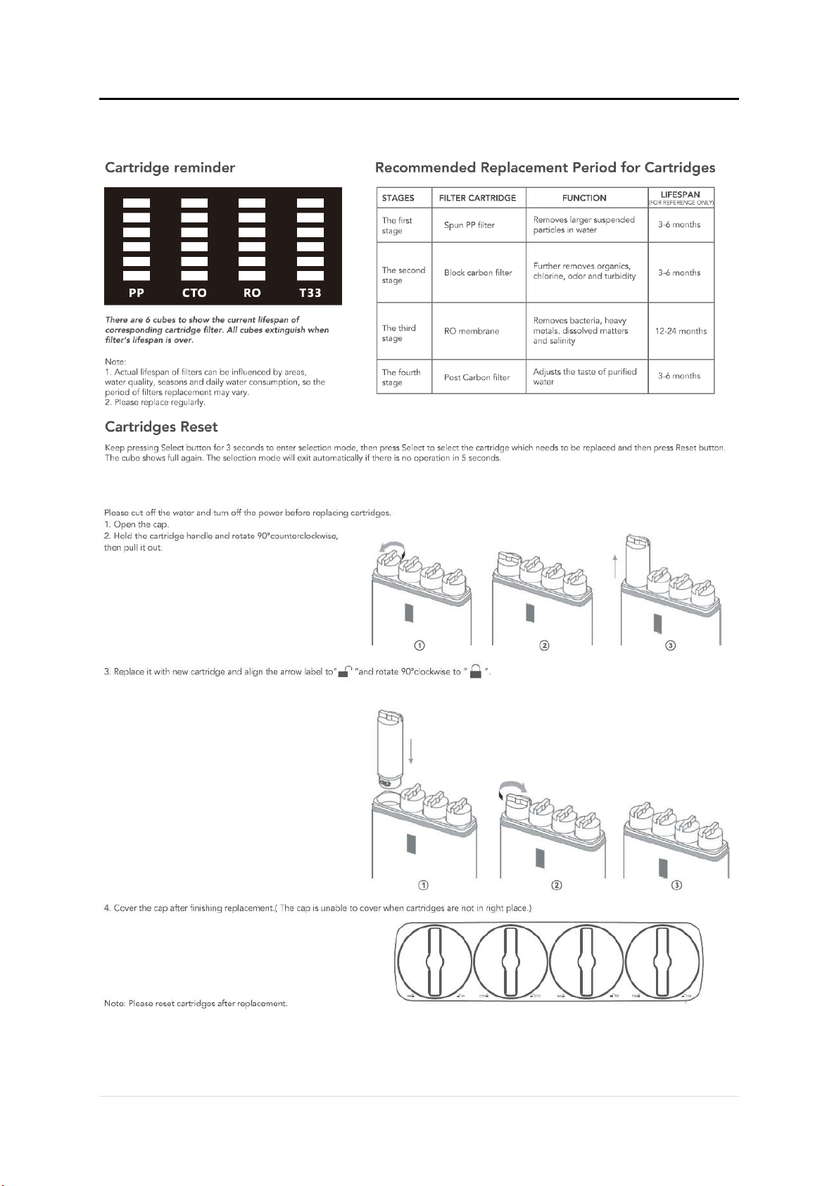
Cartridge Replacement

10 | P a g e
Troubleshooting
Trouble
Cause
Solution
Water pump is out of
service and the system
does not work
Insufficient feed water
pressure
Increase feed water
pressure
No power or power failure
Power on
High pressure switch is
out of order
Replace High Pressure
Switch
Pump is block and power
adapter fuse is burned
out
Replace Power adapter
and repair water pump
High TDS Value
TDS of feed water is too
high, or system has not
been used for a long
period of time
Open the tap to draw
water off the purified
water for 10-15 minutes
Cartridge lifespan is over
Replace cartridge
Water pump works but
system does not work
RO membrane is Blocked
Replace RO Membrane
Water Pump pressure
loss
Repair water pump
Flush Solenoid valve is
damaged
Replace flush Solenoid
Valve
Constantly running water
in downtime
Inlet water solenoid valve
damaged
Replace fee water
Solenoid Valve
Cannot stop working
when a pressure tank is
full or repetitive starting
High pressure switch is
damaged
Repair or replace High
Pressure Switch
Check valve is Damaged
Replace Check Valve

11 | P a g e
Precautions for Use
ATTENTION
1. Flush and replace cartridge regularly.
2. Do not disassemble parts randomly as it may cause leakage or damage.
3. Do not use power supply with unsupported voltage.
4. Please disconnect power and turn off Main feed water Valve if the system will not be
used for long periods of time.
5. Do not store or explore in an environment of 0 ºC or below.
6. Handle with care when discharging, moving, and installing.
REMINDER
1. If any “Water Hammering”occurs on the system, Crystal Water will NOT take
responsibility or consequences regarding any damage of malfunctions caused.
2. Please disconnect power and turn off water to the system at once in case troubles
occur and ask professional staff to repair.
3. Professional staff are advised to replace cartridges only. For any other faults, a
Technician may be required, or postage of the system may be required for repair.
4. It is normal to hear vibrations when the system is producing water.

12 | P a g e
Commissioning Checklist
Water Diverter Installed onto Cold Line Water Supply.
In-line PLV Check Valve Installed before Filtration System.
Drain clamp is secured and fitted correctly.
Locking clips are installed on Push-Fit connections.
Inlet and outlet connections are properly fitted and well secured (if
applicable)
Tap Fitting Installed onto Threading
Water has been run for at least 10 to 15 minutes before use.
If any difficulties arise contact Crystal Water: Phone +61 8 6244 1300.
For information on our Filtration and Service Contracts please contact Crystal Water
Customer Service on +61 8 6244 1300 or service@crystalwaterperth.com.au.

13 | P a g e
Warnings
For continued safety of this appliance it must be installed, operated and maintained in accordance with the
manufacturer’s instructions. For correct operation of this appliance, it is essential to observe the instructions
as outlined in this booklet.
—Your unit should be installed by a suitably qualified tradesperson.
—For correct operation of this unit it is essential to observe the instructions as outlined in this booklet.
—Do not use this unit with water that is microbiologically unsafe or with water of unknown quality without
adequate disinfection before or after the system. Systems certified for cyst reduction may be used on disinfected
water that may contain filterable cysts.
—Use this unit only as directed in these instructions and relevant Crystal Water User Guides and only for its
designed purpose.
—Do not install unit if power cord is damaged.
—This unit is not intended for use by persons (including children) with reduced physical, sensory or mental
capabilities, or lack of experience and knowledge, unless they have been given supervision or instruction
concerning use of the appliance by a person responsible for their safety. Children should be supervised to ensure
that they do not play with the unit.
—This unit is designed for indoor installation only and must not be exposed to direct sunlight, rain and excessive
heat, cold, damp or dust.
—Do not store solvents or corrosive chemicals or other flammable items on or around this Unit.
—Any service or unit repairs must be performed by a trained and suitably qualified Technician.
—If the supply cord is damaged, it must be replaced by the manufacturer, its service agent or similarly qualified
persons in order to avoid a hazard.
—Packaging material including plastic bags must be kept out of reach of children and disposed of according to
local regulations.

14 | P a g e
Crystal Water
236 Fletcher Road, Karnup
Western Australia 6176, Australia
Telephone: +61 8 6244 1300
Email: service@crystalwaterperth.com.au
Crystalwaterperth.com.au
As Crystal Water has a policy of
continual improvement, all details are
subject to change without notice. All
goods are sold subject to our
published terms and conditions.
Table of contents
Other Crystal Water Water Filtration System manuals


Popular Water Filtration System manuals by other brands

NKT Photonics
NKT Photonics SUPERK SELECT Product guide

R.O. DRINKING WATER SYSTEM
R.O. DRINKING WATER SYSTEM T.F.C.-300 Installation, operation & service manual

Micronfilter
Micronfilter KALAMIT Series Use and maintenance manual

EWS
EWS UF3020 instruction manual

Newa Pond
Newa Pond PURO advance Instructions and guarantee

Hydro Action
Hydro Action AP Series owner's manual


BWT
BWT AQA drink Ho.Re.Ca. General instructions

Hayward
Hayward SWIMCLEAR C3030EURO owner's manual

Master Water Conditioning
Master Water Conditioning Clarifier MCA Series Installation and operation manual

Savio
Savio K5003 operating manual

XpressFill
XpressFill XF4500 manual

Mitte Home
Mitte Home WK 9557 quick start guide