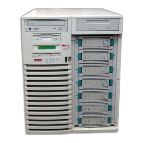
DEC AlphaServer 8200 User manual

digital equipment corporation
maynard, massachusetts
AlphaServer 8200
Installation Guide
Order Number EK–T8230–IN. A01
This guide is intended for use by Digital customer service engineers and
self-maintenance customers installing a Digital AlphaServer 8200 system.

First Printing, May 1995
The information in this document is subject to change without notice and should
not be construed as a commitment by Digital Equipment Corporation.
Digital Equipment Corporation assumes no responsibility for any errors that may
appear in this document.
The software, if any, described in this document is furnished under a license and
may be used or copied only in accordance with the terms of such license. No re-
sponsibility is assumed for the use or reliability of software or equipment that is
not supplied by Digital Equipment Corporation or its affiliated companies.
Copyright © 1995 by Digital Equipment Corporation.
All Rights Reserved.
Printed in U.S.A.
The following are trademarks of Digital Equipment Corporation: AlphaGenera-
tion, AlphaServer, DEC, DECchip, DEC LANcontroller, OpenVMS, StorageWorks,
VAX, the AlphaGeneration logo, and the DIGITAL logo.
OSF/1 is a registered trademark of the Open Software Foundation, Inc. Presto-
serve is a trademark of Legato Systems, Inc. UNIX is a registered trademark in
the U.S. and other countries, licensed exclusively through X/Open Company Ltd.
FCC NOTICE: The equipment described in this manual generates, uses, and may
emit radio frequency energy. The equipment has been type tested and found to
comply with the limits for a Class A computing device pursuant to Subpart J of
Part 15 of FCC Rules, which are designed to provide reasonable protection against
such radio frequency interference when operated in a commercial environment.
Operation of this equipment in a residential area may cause interference, in which
case the user at his own expense may be required to take measures to correct the
interference.

iii
Contents
Preface.................................................................................................... vii
Chapter 1 Installation Overview
1.1 Installation Flowchart ........................................................... 1-2
Chapter 2 Installing the System Cabinet
2.1 Inspect the Shipment............................................................. 2-2
2.2 Collect Tools and Resources .................................................. 2-4
2.3 Remove Carton and Packing Material.................................. 2-6
2.4 Remove from the Pallet ......................................................... 2-8
2.5 Level the Cabinet ................................................................. 2-10
2.6 Install Stabilizing Brackets................................................. 2-12
Chapter 3 Installing an Expander Cabinet
3.1 Unpack the Cabinet ............................................................... 3-2
3.2 Position the Cabinet............................................................... 3-4
3.3 Level All Cabinets.................................................................. 3-6
3.4 Install the Securing Brackets................................................ 3-8
3.5 Connect the Power Control Cable ....................................... 3-10
3.6 Connect the I/O Cable.......................................................... 3-12
Chapter 4 Making Console, SCSI, Ethernet, FDDI,
and DSSI Connections
4.1 Connect the Console Terminal .............................................. 4-2
4.2 Connect the Console Load Device ......................................... 4-4
4.3 Connect SCSI Cables ............................................................. 4-6

iv
4.4 Connect Ethernet Cables....................................................... 4-8
4.5 Connect FDDI Cables (Optional) ........................................ 4-10
4.6 Connect DSSI Cables (Optional) ......................................... 4-12
Chapter 5 Powering Up the System
5.1 Prepare to Check the AC Power............................................ 5-2
5.2 Measure the AC Power .......................................................... 5-4
5.3 Turn the Power On and Check Indicators ........................... 5-6
Chapter 6 System Self-Test
6.1 Check Module Status LEDs .................................................. 6-2
6.2 Check the Self-Test Display .................................................. 6-4
Chapter 7 Diagnostics and Utilities
7.1 Console Load Device .............................................................. 7-2
7.2 Verification Overview ............................................................ 7-4
7.3 Diagnostics Overview ............................................................ 7-6
7.4 Run System Self-Test ............................................................ 7-8
7.5 Show Commands for Installation........................................ 7-10
7.6 Verify SCSI Devices ............................................................. 7-12
7.6.1 Check SCSI Devices Using Console Commands.......... 7-12
7.6.2 Check Console Output Against Physical Devices ........ 7-14
7.7 If Necessary, Run the RAID Configuration Utility............ 7-16
7.8 If Necessary, Run the EISA Configuration Utility ............ 7-18
7.9 Booting Factory Installed Software .................................... 7-20
7.10 Booting OpenVMS from a CD-ROM ................................... 7-22
7.11 Booting Digital UNIX from a CD-ROM .............................. 7-24
7.12 Set Commands for Booting ................................................. 7-26
7.13 Booting LFU from a CD-ROM............................................. 7-28
7.14 Running the System Exerciser VET ................................... 7-30
Examples
6-1 Self-Test Results ................................................................... 6-4
7-1 Self-Test Display ................................................................... 7-8
7-2 Show Configuration ............................................................ 7-10
7-3 Show Device......................................................................... 7-11

v
7-4 Checking SCSI Devices....................................................... 7-12
7-5 Running RCU ...................................................................... 7-16
7-6 Running ECU ...................................................................... 7-18
7-7 Booting the Operating System ........................................... 7-20
7-8 CD-ROM OpenVMS Boot.................................................... 7-22
7-9 CD-ROM UNIX Boot .......................................................... 7-24
7-10 Set Boot Commands............................................................. 7-26
7-11 AlphaServer 8200 LFU Booting .......................................... 7-28
7-12 Sample DEC VET User Session for Command Mode ........ 7-30
Figures
1-1 Installation Flowchart ........................................................... 1-2
2-1 Inspection Flowchart ............................................................. 2-2
2-2 Packing Material.................................................................... 2-6
2-3 Preparation and Removal from Pallet .................................. 2-8
2-4 Leveler Foot Adjustment ..................................................... 2-10
2-5 Stabilizing Bracket Installation.......................................... 2-12
3-1 Expander Cabinet ................................................................. 3-2
3-2 Expander Cabinet Positioning .............................................. 3-4
3-3 System Layout........................................................................ 3-5
3-4 Leveler Foot Adjustment ....................................................... 3-6
3-5 Installing Securing Brackets................................................. 3-8
3-6 Power Control Cable Installation........................................ 3-10
3-7 Control Panel and Jack Splitter.......................................... 3-11
3-8 I/O Cable Connections ......................................................... 3-12
4-1 System Cabinet, Console Terminal, and Printer ................. 4-2
4-2 Control Panel and Console Terminal Port............................ 4-3
4-3 KFTIA as the Console Load Device Support ........................ 4-4
4-4 KZPAA as the Console Load Device Support ....................... 4-5
4-5 System and Expander Cabinets ............................................ 4-6
4-6 Ethernet Connectors on KFTIA ........................................... 4-8
4-7 Ethernet Connectors on PCI Adapters ................................. 4-9
4-8 FDDI Connectors on KFTIA................................................ 4-10
4-9 FDDI Connectors on PCI Adapter ...................................... 4-11
4-10 DSSI Connector on KFESB ................................................. 4-12
4-11 StorageWorks Shelf with DSSI Controller ......................... 4-13
5-1 Circuit Breaker for the AC Power......................................... 5-2
5-2 Measuring System Power ...................................................... 5-4
5-3 Control Panel LEDs ............................................................... 5-6
5-4 Power Regulator..................................................................... 5-7
6-1 Powering Up and Checking the LEDs .................................. 6-2
7-1 Accessing the Console Load Device....................................... 7-2

vi
7-2 Verification Procedure ........................................................... 7-4
7-3 Diagnostic Overview .............................................................. 7-6
7-4 SCSI Disks in StorageWorks Shelves ............................... 7-14
Tables
1 AlphaServer 8200 and 8400 Documentation........................ viii
2 Related Documents ................................................................... x
2-1 Tools and Resources............................................................... 2-4
2-2 Shipping Dimensions and Weights ....................................... 2-7
3-1 Cabinet Dimensions and Weights ......................................... 3-5
4-1 SCSI Cables to Devices in Other Cabinets ........................... 4-7
4-2 FDDI Options and Cables.................................................... 4-11
5-1 AC Input Voltage Specifications ........................................... 5-5
6-1 LEDs After Self-Test.............................................................. 6-3
7-1 Diagnostics ............................................................................. 7-7
7-2 DEC VET Exercisers............................................................ 7-31

vii
Preface
Intended Audience
This manual is written for Digital customer service engineers and self-
maintenance customers who require information to install an AlphaServer
8200 system.
Document Structure
This manual uses a structured documentation design. Topics are organ-
ized into small sections for efficient reference. Each topic begins with an
abstract. You can quickly gain a comprehensive overview by reading only
the abstracts. Next is an illustration or example, which also provides
quick reference. Last in the structure are descriptive text and syntax defi-
nitions.
This manual has seven chapters as follows:
•Chapter 1, Installation Overview, provides a flowchart which sum-
marizes the installation process.
•Chapter 2, Installing the System Cabinet, shows how to unpack
and install the system cabinet.
•Chapter 3, Installing an Expander Cabinet, explains how to in-
stall one or more expander cabinets, if present.
•Chapter 4, Making Console, SCSI, Ethernet, FDDI, and DSSI
Connections, shows how to connect the console, SCSI, Ethernet, and
FDDI devices if present to the system.
•Chapter 5, Powering Up the System, explains how to start the sys-
tem by applying main power.
•Chapter 6, System Self-Test, describes the system self-test and its
results.
•Chapter 7, Diagnostics and Utilities, describes how to verify sys-
tem operation using diagnostics and utilities.

viii
Conventions Used in This Document
Icons. The icons shown below are used in illustrations for designating part
placement in the system described. A shaded area in the icon shows the
location of the component or part being discussed.
Documentation Titles
Table 1 lists the books in the AlphaServer 8200 and 8400 documentation
set. Table 2 lists other documents that you may find useful.
Table 1 AlphaServer 8200 and 8400 Documentation
Main Cabinet
Front
Expander Cabinet
Rear Front Rear
Title Order Number
Hardware User Information and Installation
Operations Manual EK–T8030–OP
Site Preparation Guide EK–T8030–SP
AlphaServer 8200 Installation Guide EK–T8230–IN
AlphaServer 8400 Installation Guide EK–T8430–IN
Service Information Kit QZ–00RAC–GC
Service Manual (hard copy) EK–T8030–SV
Service Manual (diskette) AK–QKNFA–CA

ix
Table 1 AlphaServer 8200 and 8400 Documentation (Continued)
Title Order Number
Reference Manuals
System Technical Manual EK–T8030–TM
DWLPA PCI Adapter Technical Manual EK–DWLPA–TM
Upgrade Manuals for Both Systems
KN7CC CPU Module Installation Card EK–KN7CC–IN
MS7CC Memory Installation Card EK–MS7CC–IN
KFTHA System I/O Module Installation Guide EK–KFTHA–IN
KFTIA Integrated I/O Module Installation Guide EK–KFTIA–IN
Upgrade Manuals: 8400 System Only
AlphaServer 8400 Upgrade Manual EK–T8430–UI
BA654 DSSI Disk PIU Installation Guide EK–BA654–IN
BA655 SCSI Disk and Tape PIU Installation Guide EK–BA655–IN
DWLAA Futurebus+ PIU Installation Guide EK–DWLAA–IN
DWLMA XMI PIU Installation Guide EK–DWLMA–IN
DWLPA PCI PIU Installation Guide EK–DWL84–IN
H7237 Battery PIU Installation Guide EK–H7237–IN
H7263 Power Regulator Installation Card EK–H7263–IN
H9F00 Power Upgrade Manual EK–H8463–UI
KFMSB Adapter Installation Guide EK–KFMSB–IN
KZMSA Adapter Installation Guide EK–KXMSX–IN
RRDCD Installation Guide EK–RRDRX–IN
Upgrade Manuals: 8200 System Only
DWLPA PCI Shelf Installation Guide EK–DWL82–IN
H7266 Power Regulator Installation Card EK–H7266–IN
H7267 Battery Backup Installation Card EK–H7267–IN

x
Table 2 Related Documents
Title Order Number
General Site Preparation
Site Environmental Preparation Guide EK–CSEPG–MA
System I/O Options
BA350 Modular Storage Shelf Subsystem
Configuration Guide EK–BA350–CG
BA350 Modular Storage Shelf Subsystem
User’s Guide EK–BA350–UG
BA350-LA Modular Storage Shelf User’s Guide EK–350LA–UG
CIXCD Interface User Guide EK–CIXCD–UG
DEC FDDIcontroller 400 Installation/Problem Solving EK–DEMFA–IP
DEC FDDIcontroller/Futurebus+ Installation Guide EK–DEFAA–IN
DEC FDDIcontroller/PCI User Information EK–DEFPA–IN
DEC LANcontroller 400 Installation Guide EK–DEMNA–IN
DSSI VAXcluster Installation/Troubleshooting Manual EK–410AA–MG
EtherWORKS Turbo PCI User Information EK–DE435–OM
KZPSA PCI to SCSI User’s Guide EK–KZPSA–UG
RF Series Integrated Storage Element User Guide EK–RF72D–UG
StorageWorks RAID Array 200 Subsystem Family
Installation and Configuration Guide EK–SWRA2–IG
StorageWorks RAID Array 200 Subsystem Family
Software User’s Guide for OpenVMS AXP AA–Q6WVA–TE
StorageWorks RAID Array 200 Subsystem Family
Software User’s Guide for DEC OSF/1 AA–Q6TGA–TE
Operating System Manuals
Alpha Architecture Reference Manual EY–L520E–DP
DEC OSF/1 Guide to System Administration AA–PJU7A–TE
Guide to Installing DEC OSF/1 AA–PS2DE–TE
OpenVMS Alpha Version 6.2 Upgrade and
Installation Manual AA–PV6XC–TE

Installation Overview 1-1
Chapter 1
Installation Overview
This chapter provides a quick overview of the installation procedure and
relates the steps of the procedure with chapters in this manual. It consists
of one section:
•Installation Flowchart

1-2 Installation Overview
1.1 Installation Flowchart
In general, a system is installed as shown in Figure 1-1.
Figure 1-1 Installation Flowchart
BXB-0306E-95
Multiple
Cabinets
No
Yes
Install System Cabinet Chapter 2
Chapter 3
Connect Console,
SCSI, Ethernet, Chapter 4
Power Up System Chapter 5
System Self-Test Chapter 6
Chapter 7
Verification
(Diagnostics and
Utilities)
and FDDI cables

Installation Overview 1-3
In general, the procedure is as follows (Figure 1-1):
1. Install the system cabinet as described in Chapter 2.
2. If the system has one or more expander cabinets, refer to Chapter 3 for
installation instructions.
3. Connect the console, and, if appropriate, make the Ethernet, FDDI,
and SCSI connections as described in Chapter 4.
4. Power up the system as described in Chapter 5.
5. Observe and consider the results of the system self-test as described in
Chapter 6.
6. Verify system operation by running various diagnostics and utilities as
described in Chapter 7.


Installing the System Cabinet 2-1
Chapter 2
Installing the System Cabinet
This chapter describes how to install the AlphaServer 8200 system cabi-
net. The cabinet contains the CPU, memory, at least one PCI I/O subsys-
tem, disks, and power.
If your system has an expander cabinet, unpack it and remove it from the
pallet as described in the first four sections of this chapter.
Sections in this chapter include:
•Inspect the Shipment
•Collect Tools and Resources
•Remove Carton and Packing Material
•Remove from the Pallet
•Level the Cabinet
•Install Stabilizing Brackets

2-2 Installing the System Cabinet
2.1 Inspect the Shipment
Check that all system equipment is at the installation site.
Figure 2-1 Inspection Flowchart
BXB-0012-92
Yes
Continue Unpacking
Enter in LARS Report
Notify Customer
Incomplete or
Damaged
Shipment
No
Yes Customer
Contacts Carrier
Contact
Unit Manager
Check Equipment
Against Shipping List
Missing or
Incorrect
Equipment

Installing the System Cabinet 2-3
NOTE: Physically inspect the system to be sure parts have not become loose
during shipment.
If you find a damaged container or package, notify the customer. Wait un-
til the customer contacts the insurance company and gives you permission
to continue unpacking.
Compare items listed on the Product Delivery Document (in a slip envelope
on the shipping box) with the packing slip contained in a plastic envelope
on the shipping box. Items should be compared throughout the installa-
tion procedure as boxes are unpacked and cabinets are opened.
It is important to record information on damaged or opened containers on
the Labor Activity Reporting System (LARS) form.

2-4 Installing the System Cabinet
2.2 Collect Tools and Resources
You will need the items listed in Table 2-1 to unpack and install
the system cabinet. The removal of the cabinet from the pallet re-
quires at least two people.
Table 2-1 Tools and Resources
Item Use
Product Delivery
Document and
packing slip
To verify that all hardware has been delivered
Utility knife To remove straps from cabinet shipping boxes
Adjustable
wrench To remove pallet brackets and to adjust leveler feet
Level To verify that the cabinet is properly leveled
Socket wrench set To remove and install bolts
Digital voltmeter To check AC and DC voltages
Table or bench Work space for unpacking and installation
Flathead screw-
driver For installation of I/O port module cable(s)

Installing the System Cabinet 2-5
Review requirements such as power, environmental, and space require-
ments for the system.
NOTE: Since the cabinet is heavy and has a high center of gravity, remov-
ing it from the pallet requires at least two people.
For more information:
Site Preparation Guide

2-6 Installing the System Cabinet
2.3 Remove Carton and Packing Material
Take off the carton and remove all packing material to prepare the
system cabinet for removal from the pallet.
Figure 2-2 Packing Material
BXB-0096A-92
7
6
5
Other manuals for AlphaServer 8200
1
Table of contents
Other DEC Server manuals

DEC
DEC Digital AlphaServer 400 series Operation manual

DEC
DEC AlphaServer 8200 User manual

DEC
DEC AlphaServer 2100 User manual

DEC
DEC 4000 AXP User manual

DEC
DEC DECNIS 600 Manual

DEC
DEC Rackmount 7000 AXP User manual

DEC
DEC 4000 600 series User manual

DEC
DEC 4000 Model 200 User manual

DEC
DEC Rackmount 7000 AXP Instruction Manual

DEC
DEC 3000 Model 400S Operating instructions