CS-Electronic CS-Super Sport Magnetic BL User manual
Logo
CS-ELECTRONIC
CS-ELECTRONIC GmbH I Johann-Karg-Str.30 I 85540 Haar
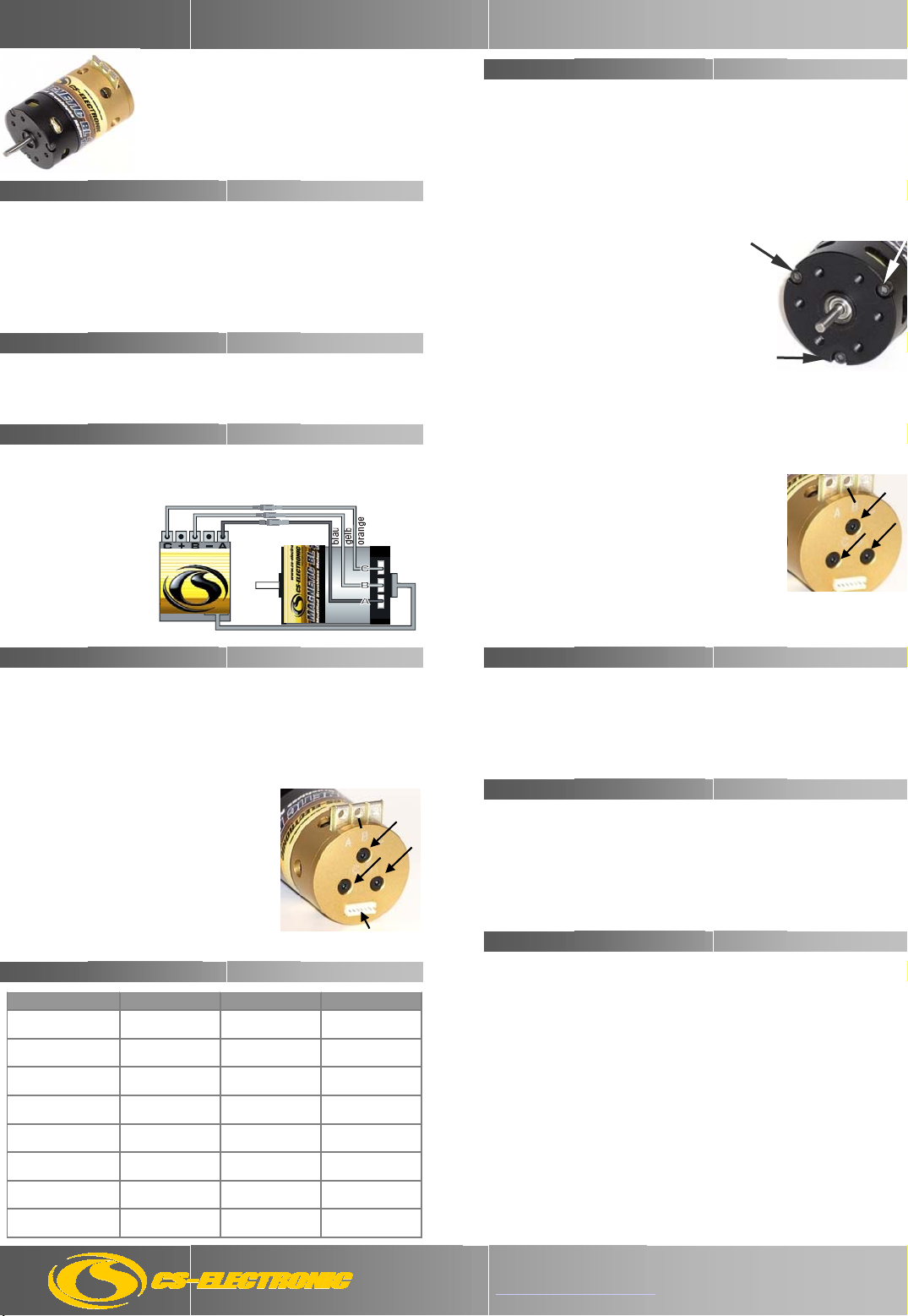
Befestigen Sie den Motor im Fahrzeug. WICHTIG: die maximale Länge der
Befestigungsschrauben darf 4 mm nicht überschreiten. Löten Sie die drei
ESC Kabel an die Lötfahnen des Motors, wie in der Zeichnung aufgeführt.
Wenn Sie einen Sensor-ESC
benutzen, stecken Sie das
Sensor-Kabel in die Buchse
am Boden des Motors und
verbinden so Motor mit
Regler.
Prüfen Sie anschliessend
alle Verbindungen, bevor
Sie den Motor in Betrieb
nehmen.
4. Timing
Beachten Sie unbedingt alle Hinweise, da diese Ihren Motor zerstören können
und die Gewährleistung ausschließen. Löten Sie bei Verwendung des CS-
Magnetic Brushless Modified Motors niemals eine Schottky-Diode an den
Motor oder Fahrtenregler. Vermeiden Sie, beim Wechseln der Powerkabel
länger als 5 Sekunden je Lötstelle zu löten, um eine Beschädigung der
Bauteile durch Überhitzung auszuschließen. Vermeiden Sie zu festes Anziehe
n
der Motorschrauben. Überdrehte Gewinde sind kein Gewährleistungsfall.
8. Service
Sollten trotz sachgerechter Handhabung und ausreichender Pflege Probleme
auftreten oder wurde der Motor beschädigt, senden Sie den Motor mit kurzer
und präziser Beschreibung des Problems, Mangels oder der Beschädigung an
CS-ELECTRONIC GmbH, Johann-Karg-Str. 30, D-85540 Haar bei München.
Mit dem Einsenden des Produktes erteilen Sie uns einen Reparaturauftrag.
Auf Ihren ausdrücklichen Wunsch erstellen wir einen Kostenvoranschlag, der
kostenpflichtig ist, sollten Sie anschliessend die Reparatur nicht durchführen
lassen.
CS-ELECTRONIC Produkte werden nach strengsten Qualitätskriterien
gefertigt und CS-ELECTRONIC GmbH garantiert, dass die Motoren in
einwandfreiem Zustand ausgeliefert werden. CS-ELECTRONIC gewährt die
gesetzliche Gewährleistung auf Produktions- und Materialfehler, die zum
Zeitpunkt der Auslieferung des Produktes vorhanden waren. Für
gebrauchstypische Verschleißerscheinungen wird nicht gehaftet. Die
Gewährleistung gilt nicht für Mängel, die auf natürliche Abnutzung/Verschleiß,
eine unsachgemäße Benutzung oder mangelnde Wartung zurückzuführen
sind. Jeglicher Gebrauch des Produktes folgt auf eigene Gefahr.
Ein Gewährleistungsanspruch kann nur anerkannt werden, sofern beim
Einsendung des Produktes eine Kopie des Kaufbeleges beigefügt ist. Die
Gewährleistung übersteigt in keinem Fall den Wert des Produktes.
Durch Inbetriebnahme des Produktes erkennen Sie die obigen Bedingungen
an und übernehmen die volle Verantwortung aus dem Gebrauch dieses
Produktes.
Die von CS-ELECTRONIC angegebenen Werte über Gewicht, Größe oder
Sonstiges sind als Richtwert zu verstehen. CS-ELECTRONIC übernimmt
keine formelle Verpflichtung für derartige spezifische Angaben, da sich durch
technische Veränderungen, die im Interesse des Produktes vorgenommen
werden, andere Werte ergeben können.
B
Sensorkabel
Sensorkabel
Anschluss
PIC 1
PIC 2
B
Gelegentlich ist es notwendig, die Kugellager des Motors zu überprüfen und
zu ölen und Schmutz, der sich innen im Motor befindet, zu entfernen. Um
die Kugellager zu ölen, lösen und entfernen Sie die drei Schrauben an der
Bodenplatte PIC 2 ( notieren Sie sich die Timing Position für die Wieder-
montage). Das hintere Kugellager befindet sich im hinteren Lagergehäuse.
Geben Sie einen Tropfen eines Kugellageröls ( wir empfehlen das JRP-Öl
J21220 ) auf das hintere Kugellager. Dann montieren Sie die Bodenplatte
wieder zurück und ziehen Sie die Schrauben wieder an. Das vordere
Kugellager erhält ebenfalls einen Tropfen Öl, dazu muss jedoch der Motor
nicht demontiert werden.
Beim Zerlegen des Motors für Lager- oder
Rotorenwechsel gehen Sie wie folgt vor:
1. Lösen und entfernen Sie die drei Schrauben
am vorderen Lagergehäuse PIC 1 des Motors.
2. Dann entfernen Sie das vordere Kugel-
Lager. Es ist zu empfehlen, dies mit einem
speziellen Werkzeug durchzuführen.
3. Das alte Lager tauschen Sie gegen ein neues aus.
4. Entnehmen Sie vorsichtig den Rotor aus dem
Motor. Wegen seiner magnetischen Anziehung halten
Sie andere magnetische Teile und Werkzeuge fern und platzieren Sie den
Rotor an einen sicheren Ort. Achten Sie auf die Positionen aller Distanz-
scheiben, um den Motor wieder korrekt montieren zu können.
5. Lösen Sie die drei Schrauben an der Bodenplatte
PIC 2 ( notieren Sie sich die Timing Position für die
Wiedermontage) und entfernen Sie die Bodenplatte.
6. Dann drehen Sie langsam das hintere Lager-
Gehäuse mit der Platine um 30Grad nach links oder
rechts und entfernen es vorsichtig. Entfernen Sie das
Kugellager und setzen Sie ein neues ein.
Achtung: Die Sensorplatte ist mit dem hinteren
Lagergehäuse verbunden und sehr empfindlich.
7. Wenn Sie den Motor wieder richtig montiert haben, sollte der Rotor ein
sehr kleines oder kein Spiel haben. Setzen Sie Distanzscheiben zwischen
dem vorderen Lager und dem Rotor um das Spiel korrekt einzustellen.
# C110301 CS-Super Sport Magnetic BL 9,5T
# C110302 CS-Super Sport Magnetic BL 11,5T
# C110303 CS-Super Sport Magnetic BL 13,5T
Einsatzbereich 9,5T 11,5T 13,5T
Tourenwagen
5 Zellen (kleine Strecke)
6,0 : 1 5,5 : 1 5,0 : 1
Tourenwagen
5 Zellen (große Strecke)
5,5 : 1 5,0 : 1 4,5 : 1
Tourenwagen
6 Zellen (kleine Strecke)
7,2 : 1 6,7 : 1 6,2 : 1
Tourenwagen
6 Zellen (große Strecke)
6,6 : 1 6,1 : 1 5,6 : 1
1/12 Scale
4 Zellen
49mm 51mm 53mm
2WD Off-Road
6 Zellen
10,0 : 1 9,0 : 1 8,0 : 1
4WD Off-Road
6 Zellen
10,5 : 1 9,5 : 1 8,5 : 1
Monster Truck
6 Zellen
11,0 : 1 10,0 : 1 9,0 : 1
Gebrauchsanweisung CS-Magnetic Super Sport BL Motoren
6. Wartung / Maintenance
1. Sehr geehrter Kunde
Wir gratulieren Ihnen zum Erwerb des CS-Super Sport Brushless Motors.
Sie haben sich für ein qualitativ hochwertiges Produkt von einer der
traditionsreichsten und innovativsten Modellbaufirmen Deutschlands
entschieden. Bevor Sie den CS-Super Sport Brushless Motor einsetzen,
lesen Sie bitte die folgenden Informationen aufmerksam durch, um
sicherzustellen, dass Ihr Motor stets zu Ihrer vollsten Zufriedenheit
funktioniert. Mit der Inbetriebnahme des Produkts erklären Sie sich mit den
Gewährleistungsbedingungen einverstanden.
2. Einsatzbereich
Der CS-Super Sport Brushless Motor ist konzipiert für RC-Cars laut unserer
Empfehlungen für 1:12 und 1:10 Modelle mit einer Betriebsspannung von
4,8 – 7,4V. Er kann mit allen aktuellen Sensor- und sensorlosen Brushless
Elektronik Fahrtenregler (ESC) betrieben werden.
3. Anschluß
7. Warnhinweise
Ihr Fahrtenregler (ESC) hat meistens ein voreingestelltes Timing in der Regler-
Software. Bitte überprüfen Sie in der ESC Bedienungsanleitung, ob Sie ein
passendes Timing-Programm für diesen Mototyp wählen können. Das Timing
des CS-Magnetic Brushless Modified Motors ist so voreingestellt, dass das
bestmögliche Power- und Effizienz-Verhältnis erreicht wird. Sie können aber
das Timing verändern um den Motor an unterschiedliche Streckenverhältnisse
anzupassen. Bitte gehen Sie folgendermaßen vor:
1. Lösen Sie die drei Schrauben am Motorkopf
2. Notieren Sie sich die Position des Original-
Timings, „B“ ist mittig der mittleren Lötfahne
3. Für mehr Drehzahl drehen Sie die
Bodenplatte entgegen dem Uhrzeigersinn.
4. für mehr Effizienz und weniger
Drehzahl drehen Sie die Boden-
platte im Uhrzeigersinn.
Bitte beachten Sie: bei einer Erhöhung des
Timings steigt der Stromverbrauch und Sie
müssen eine kürzere Übersetzung verwenden. 8. Gewährleistung
5. Untersetzung

User`s Manual CS-Magnetic Super Sport BL Motor
# C110301 CS-Super Sport Magnetic BL 9,5T
# C110302 CS-Super Sport Magnetic BL 11,5T
# C110303 CS-Super Sport Magnetic BL 13,5T
Casually it is necessary to test the ball bearings of the motor and to oil them,
also to delete the dirt from inside the motor. To oil the ball bearings loosen
and remove the three crews on the back plate ( note the timing position for
re-assembly). The rear ball bearing is located inside the rear bearing
housing. Place one drop of bearing oil (we recommend JRP-OIL J21220) on
the rear ball bearing. Then re-assemble the back plate and tight the back
plate screws. Also the front ball bearing gets a drop of oil, for this you must
not remove the motor.
For changing the ball bearings or the rotor of
the motor disassemble the motor as follows:
1. loosen and remove the three screws on the front
bearing housing PIC 1 of the motor.
2. Then remove the front ball bearing. We advise to
do this with a special removal tool.
3. Exchange the old ball bearing with a new one.
4. Carefully remove the rotor from the motor.
Because of its magnetic attraction keep away all
magnetic objects and tools and place the rotor in
a safe spot. Attend the position of all spacers to
can re-assemble the motor correctly.
5. Loosen the three screws on the back plate PIC 2
(note timing position) and remove the back plate.
6. Then slowly turn the rear bearing housing, with the
plate, 30 degree to the left or right and remove it
carefully. Delete the ball bearing and insert a new one.
Attention: The sensor plate is attached to the rear
bearing housing and is very sensitive. When you again
have assembled the motor accurately the rotor should have a very little or
no side play. Place the spacers between the front ball bearing and the rotor
to adjust the play correctly.
7. Warnings
Pay attention strictly all details otherwise your motor can be destroyed and
the warranty is excluded.
Using a CS-Magnetic Brushless Modified Motor never sold a Shottky diode
on the motor or ESC. When changing the power wire avoid to sold no longer
than 5 sec. every sold position to except any damage of components. Also
avoid too hard tightening of the motor screws. Overwinded screw threads
are no case of warranty conditions.
8. Service
If you have problems with your motor in fact of appropriate handling and
sufficient support or if your Motor has been damaged you can send them to
CS-ELECTRONIC GmbH, Johann-Karg-Str. 30, DE-85540 Haar bei
München. Please include the motor a specific description of the problem or
the damage. With the send in of the product you place a repair order. If you
wish we can give you a quotation about the repair costs. If then afterwards
you do not let repair the motor the quotation will be with costs.
PIC 1
PIC 2
B
6. Maintenance
1. Dear Customer:
Congratulations for your purchasing of our CS-Super Sport Brushless Motor.
You have decided in favour of a high–quality product of one of the most
traditional and most innovative modelling companies of Germany.
Before employing the CS-Super Sport Brushless Motor please read the
following instructions carefully to ensure that your motor works to your
complete satisfaction. With starting the motor you accept our conditions of
warranty.
2. Range of applications:
The CS-Super Sport Brushless Motor is designed for RC-Car models 1:12 and
1:10 with an operating voltage of 4.8 – 7,4V. This motor can be used with all
current sensorless and sensored brushless electronic speed controls (ESC).
3. Installation:
Fix the motor in your car. Attention: the maximum length of the mounting
screws must not be longer than 4 mm. Solder the three ESC wires to each of
the solder taps on the motor like shown on the drawing.
When you use a sensor
ESC plug the sensor wire
into the connector located
on the back plate of the
motor.
Afterwards test all
connections before you
start the motor.
Sensorwire
4. Timing
Your speed control ( ESC) mostly has a preset timing in its software. Please
check in the ESC manual if you can choose a relevant timing program for your
motor type. The base timing of the CS-Magnetic Brushless Motor is pre-set to
give the best possible power/efficiency ratio. But you can change the timing to
accommodate the motor to different track measures. Then please use the
following procedure:
1. Slightly loosen the three screws on the
motor head.
2. Note the timing position of the original
timing, “B” is middle of the middle solder tab.
3. For more speed level turn the back plate
counterclockwise .
4. For more efficiency and less speed level turn
the back plate clockwise.
Please note: if you increase the timing the
wattage will rise and you have to take a
shorter ratio.
B
Sensor wire
Connector 8. Warranty Conditions
CS-ELECTRONIC products are produced under strictly criterions of quality
and CS-ELECTRONIC guarantees that the motors are supplied in correctly
condition. CS-ELECTRONIC concede the legal warranty for faults of
production and material which were existed at the time of supply. We are not
liable for use typical signs of wear. The warranty do not apply for defects
which a traced back to natural wastage, faulty use and failing maintenance.
Every use of the product is at owner’s risk. We only can accept a warranty
claim if a copy of the sales slip is encluded when sending the product. The
warranty in no case overrun the value of the product.
When you start up with the product you accept the conditions above and
assume full responsibility using this product.
The values about weight, size and others specified by CS-ELECTRONIC are
only bench marks. CS-ELECTRONIC does not assume any liability for these
specifications for technological changes on behalf of the product can arise
other values.
5. Gear Ratio:
Condition 9,5T 11,5T 13,5T
Touring Car
5 cells, small tracks
6,0 : 1 5,5 : 1 5,0 : 1
Touring Car
5 cells, large tracks
5,5 : 1 5,0 : 1 4,5 : 1
Touring Car
6 cells, small tracks
7,2 : 1 6,7 : 1 6,2 : 1
Touring Car
6 cells, large tracks
6,6 : 1 6,1 : 1 5,6 : 1
1/12 Scale
4 cells
49mm 51mm 53mm
2WD Off-Road
6 cells
10,0 : 1 9,0 : 1 8,0 : 1
4WD Off-Road
6 cells
10,5 : 1 9,5 : 1 8,5 : 1
Monster Truck
6 cells
11,0 : 1 10,0 : 1 9,0 : 1
Logo
CS-ELECTRONIC
CS-ELECTRONIC GmbH I Johann-Karg-Str.30 I D85540 Haar
This manual suits for next models
3
Table of contents
Languages:
Popular Engine manuals by other brands

Varvel
Varvel RC series Working Instructions and Maintenance

Nice
Nice NX FIT MB 534 SH BD quick guide

WEICHAI
WEICHAI R6160 Series operating instructions

Bullitt
Bullitt B-219 instruction manual

Bosch
Bosch Performance Line: SX BDU3182 owner's manual

Snow Performance
Snow Performance Diesel Stage 2 Boost Cooler installation instructions

RADEMACHER
RADEMACHER RolloTube S-line DuoFern Brief instructions for installation and initial commissioning

HRW
HRW HPE8884P1 manual

Briggs & Stratton
Briggs & Stratton 319700 Series Illustrated parts list

Lombardini
Lombardini LDW 502 Use maintenance and consumer information

Hoval
Hoval MRHX-02N manual

Lombardini
Lombardini 11LD522-3 Series Workshop manual


