CS-Lab CSMIO-ENC User manual

© copyright CS-Lab s.c. 2019: Rev 3.1 (20/12/22)
CSMIO-ENC
Encoder module for
threading

www.cs-lab.eu
CS-Lab s.c. | CSMIO-ENC module for threading
2
CONTENT
1. CSMIO-ENC general ...................................................................Błąd! Nie zdefiniowano zakładki.
1.1 Signs used in this guide ....................................................................................................... 3
1.2 Standards compliance ......................................................................................................... 3
2. CSMIO-ENC module signals connector ....................................................................................... 4
2.1 Encoders connector ............................................................................................................ 4
2.2 Connector for CSMIO/IP control connection....................................................................... 5
2.3 Expansion modules connector ............................................................................................ 5
3. VisualBasic® macro use............................................................................................................... 6
3.1 GetInput – position (16 bit) and angle read out.................................................................. 6
3.2 GetUserDRO – position read out (32 bit) ............................................................................ 6
4. CSMIO-ENC module installation and configuration .................................................................... 7
4.1 Installation and connection of CSMIO-ENC module............................................................ 7
4.2 CSMIO-ENC module configuration ...................................................................................... 7

www.cs-lab.eu
CS-Lab s.c. | CSMIO-ENC module for threading
3
1. General
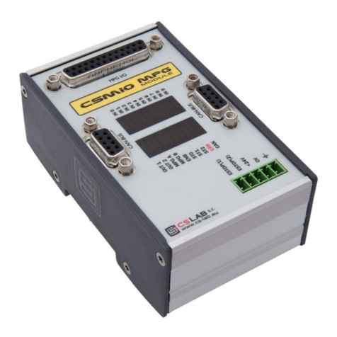
The CSMIO-ENC is an expansion module for threading and it’s used to connect spindle encoder. It can
be used with CSMIO/IP-S (step/dir) and CSMIO/IP-A (+/-10V) Ethernet Motion Controllers.
1.1 Signs used in this guide
Potential danger, possible risk of injury.
Useful information, tips
Warning, failure to comply with these warnings may lead to inappropriate functioning or
damage to the device
1.1 Content of the package
In the CSMIO-ENC module package you will get:
1x DB25 flat cable
1x DB9 flat cable
1x DB25 connector -> terminal block.
1x terminator
1.2 Standards compliance
CSMIO-ENC modules were designed and made in accordance with the national and international
standards for industrial control systems based on electronic components:
•Detailed requirements for programmable controllers: working characteristics, shock
resistance, safety etc. EN61131-2 (IEC1131-2), CSA 22.2, UL508
•Compliance with European Guidelines (low voltage, the level of electromagnetic interference
Electromagnetic Compability), the CE marking.
•Electrical and non-combustible properties of insulation materials: UL 746C, UL 94, etc.
•The Product made in lead-free technology, RoHS compliant.

www.cs-lab.eu
CS-Lab s.c. | CSMIO-ENC module for threading
4
2. CSMIO-ENC module signals connector
2.1 Encoders connector
PIN number
Description
1
+5V
2
encoder 0 - IN A+
3
encoder 0 - IN B+
4
encoder 0 - IN I+
5
+5V
6
encoder 1 - IN A+
7
encoder 1 - IN B+
8
encoder 1 - IN I+
9
+5V
10
encoder 2 - IN A+
11
encoder 2 - IN B+
12
encoder 2 - IN I+
13
NC
14
GND
15
encoder 0 - IN A-
16
encoder 0 - IN B-
17
encoder 0 - IN I-
18
GND
19
encoder 1 - IN A-
20
encoder 1 - IN B-
21
encoder 1 - IN I-
22
GND
23
encoder 2 - IN A-
24
encoder 2 - IN B-
25
encoder 2 - IN I-
To use the CSMIO-ENC module on a lathe we use only encoder channel 0.
The encoder needs to have 5V
differential outputs.
The maximum total load of encoder power supply outputs is 500mA.

www.cs-lab.eu
CS-Lab s.c. | CSMIO-ENC module for threading
5
2.2 Connector for CSMIO/IP control connection
2.3 Expansion modules connector
PIN no.
Description
1
CAN H
2
-
3
-
4
-
5
GND
6
CAN L
7
RS485 B-
8
RS485 A+
9
-
PIN no.
Description
1
CAN H
2
RS232 RxD
3
RS232 TxD
4
-
5
GND
6
CAN L
7
RS485 B-
8
RS485 A+
9
-
The connectors are designed only for extension modules by CS-Lab s.c. They
cannot be used to connect any other devices, PC etc.
For correct module operation it is enough to connect the lines (CAN H ; CAN L ;
GND). Lines (RS485 B- ; RS485A+) are used in other CSMIO modules and it may be
required to connect them for correct operation of following modules.

www.cs-lab.eu
CS-Lab s.c. | CSMIO-ENC module for threading
6
3. VisualBasic® macro use
3.1 GetInput – position (16 bit) and angle read out
With this command you can read position counter for each encoder inputs as well as the spindle angle
(encoder channel 0).
Syntax:
GetInput (addr)
Parameters:
addr - register addresses (look at the table below)
Register no.
Description
84
Spindle angle multiplied x10 (range 0-3600)
85
Encoder channel 0 position counter (spindle)
86
Encoder channel 1 position counter
87
Encoder channel 2 position counter
3.2 GetUserDRO – position read out (32 bit)
With this command you can read position counter in 32bit format.
Syntex:
GetUserDRO (addr)
Parameters:
addr - register address (look at the table below)
Register no.
Description
1501
32 bit encoder channel 0 position counter
1502
32 bit encoder channel 1 position counter
1503
32 bit encoder channel 2 position counter

www.cs-lab.eu
CS-Lab s.c. | CSMIO-ENC module for threading
7
4. CSMIO-ENC module installation and configuration
4.1 Installation and connection of CSMIO-ENC module
An encoder should be mounted this way to get encoder- spindle ratio 1:1. The encoder most be firmly
mounted and parts used for driveline must be finely made.
For instance if we have to use a belt drive for the encoder's drive we need to pay attention if gears
and toothed belts are good quality.
Poorly made gears and toothed bars can distort spindle's current position readout what can directly
affect on Z axis feed during threading.
It is not recommended to use an encoder of a servo motor that drives the spindle to avoid spindle
position readout error.
CSMIO-ENC module connection
−The module should be connected to a motion controller (CSMIO/IP-S or CSMIO/IP-A) with the
flat cable included.
−A power supply of the module should be connected the same way as the head controller's
power supply.
−Spindle encoder signals should be connected to inputs described as "encoder 0" as only these
inputs are supported by an algorithm for threading and revs reading.
During an encoder connection remember to keep proper signals' order.
4.2 CSMIO-ENC module configuration
The encoder module configuration is very easy and it comes down to only to operations:
a) Encoder pulses number configuration
Go to „Config\Config Plugins\Config\Special Functions\Spindle” and enter encoder pulses
number incl. all edges in the „Spindle Encoder (CSMIO-ENC)” area.
b) Encoder pulses counting direction configuration
Sometimes it can be necessary to change encoder pulses counting direction. To verify if
current direction is correct you should go to „PlugIn Control\CSMIO_IP plugin\Expansion
modules\CSMIO-ENC\”. Then - activate a spindle with M3 command and verify if RPM value is
positive. If it will be negative you should go to „Config\Config Plugins\Config\Special
Functions\Spindle” and select (check) „Inv. Direction” option.
CSMIO-ENC for proper operation requires all encoder signals (A+/A-/B+/B-/I+/I-).
A shield of an encoder's wire should be connected only from one side to PE or in case of
high noises to GND (0V). CSMIO-ENC power connector can be the place of connection.
Table of contents
Other CS-Lab Control Unit manuals
Popular Control Unit manuals by other brands
Keysight
Keysight N3304A Component level information
Armstrong
Armstrong 425 Installation and Maintenance
Mitsubishi Electric
Mitsubishi Electric CC-Link IE TSN user manual
Watts
Watts 909 Series Installation, maintenance & repair
TECH
TECH Sinum PS-08m 230 quick start guide
Bardiani Valvole
Bardiani Valvole BBZO Instruction, use and maintenance manual
Automated Logic
Automated Logic LGE Technical instructions
Digi
Digi XBee SX 868 user guide
Duemmegi
Duemmegi Domino DFCKIII manual
YASKAWA
YASKAWA DO-A3 installation manual
GEM
GEM 563 Installation, Operating and Maintenance Instructions for the Installer and the User
SMC Networks
SMC Networks IL201 Series Operation manual
