EG-3P Actuator Manual 82560
8 Woodward
Actuator Operating Useful
Oil Pressure Work Output
400 psi (2758 kPa) 3.00 ft-lb (4.07 J)
300 psi (2068 kPa) 2.25 ft-lb (3.05 J)
200 psi (1379 kPa) 1.50 ft-lb (2.03 J)
100 psi (690 kPa) 1.00 ft-lb (1.36 J)
Table 1-1. Typical Governor Oil Pressure vs Useful Work Output
For emergency start-ups, Woodward recommends an oil sump to furnish
immediate oil to the actuator.
The EG-3P actuator normally goes to minimum fuel if the electric signal is
interrupted. Oil for the EG-3P actuator is taken from the engine lubricating
system or from a separate sump (not furnished by Woodward).
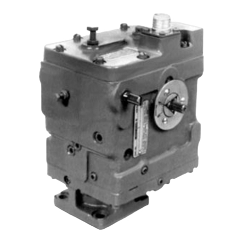
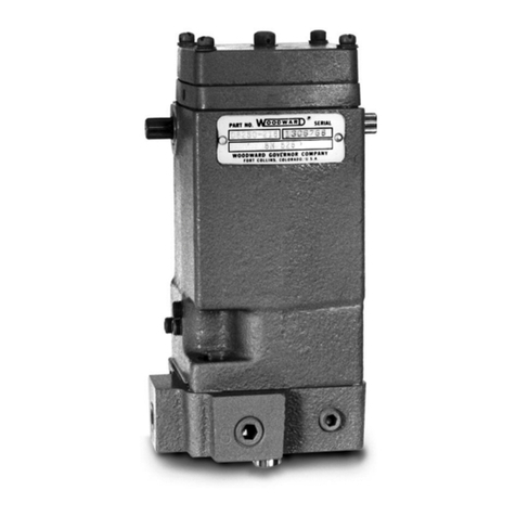
An EG-3P actuator can be furnished with or without a drive shaft. The drive shaft
of a unit fitted with such a shaft can be driven by the prime mover or some other
means to provide relative rotation between the pilot valve plunger and bushing
and to rotate the oil pump gears. The drive shaft should rotate between 1200 and
3600 rpm. It can rotate in one direction only. The direction of rotation is
determined by the placement of plugs in the oil passages in the actuator base
and case. A relief valve is incorporated within the actuator to maintain the
operating oil pressure at approximately 350 psi (2413 kPa) above supply
pressure.
An EG-3P actuator not fitted with a drive shaft is equipped with an oil motor.
Actuators with oil motors do not have oil pumps. Oil under pressure must be
supplied to provide working pressure for the actuator and to operate the oil motor
which rotates the pilot valve bushing. Oil supply to the Oil Motor is restricted by
an orifice. The size of the orifice depends upon the pressure supplying the unit
on the following scale:
Supply Pressure Orifice Diameter
80 to 99 psi (552 to 687 kPa): 0.076” (1.93 mm) dia.
100 to 175 psi (688 to 1210 kPa): 0.062” (1.57 mm) dia.
176 to 300 psi (1211 to 2071 kPa): 0.055” (1.40 mm) dia.
301 to 500 psi (2072 to 3448 kPa): 0.047” (1.19 mm) dia.
The orifice size is supplied inside most of the actuators at the time of purchase
and is matched to the specified supply pressure.
Some actuators are designed to have a separate supply line to the oil motor and
in these instances the orifice is placed in the connection to the oil motor rather
than in an internal oil passage.
Work output of the EG-3P actuator equipped with an oil motor depends upon the
pressure of the oil supplied to the actuator. With a 400 psi (2758 kPa) supply
pressure, the actuator output would be 4.5 ft-lb (6.1 J).
Operation
Oil from the external source enters the suction side of the oil pump. The pump
gears carry the oil to the pressure side of the pump, first filling the oil passages
and then increasing the hydraulic pressure. When the pressure becomes great
enough to overcome the relief valve spring force and push the relief valve
plunger down to uncover the bypass hole, the oil recirculates through the pump.
