480-12, -15, & -16 Series
Type 481 Combinations
Fisher Type 481 actuator combinations are the basic piston
actuators without integral cylinder loading devices. A
suitable switching device (supplied by the customer)
provides for loading the top or bottom of the cylinder.
Type 489 Combinations
The Type 3579 solenoid manifold acts to alternately load
and exhaust opposite sides of the piston in response to
electrical signals from an outside power source. Since the
solenoid valves are the normally closed type. they lock the
hydraulic fluid in the piston actuator when the circuit is
opened. Thus the actuator can be positioned at any point in
the stroke by opening an external switch at the appropriate
time.
When an external switch is moved to the “DOWN”
position. solenoid valves #I and #4 open as shown in the
figure 3 schematic. Hydraulic fluid flows through solenoid
#4 to load the top of the cylinder while fluid below the
piston flows back to the oil sump through solenoid #I.
Operation continues in this manner until the circuit is
broken. When switched to the “UP” position. solenoid
valve #5 opens to load the bottom of the cylinder and
solenoid valve #2 opens to exhaust the top of the cylinder.
Bypass Piping
If the valve or louver operated by the piston actuator can
also be operated manually, the optional bypass assembly
(figure 7) may be required. Opening the hand valve (key
121, figure 7) allows the operating fluid to flow freely
between the top and bottom of the cylinder. Closing the
hand valve will allow pneumatic or hydraulic operation to
continue.
Adjustments
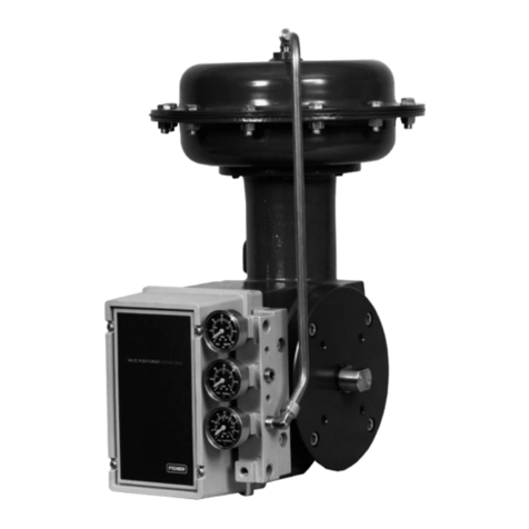
All adjustments on the Type 480 actuator combinations are
on the Type 3570 or 3570C positioner. For further
information on the positioner, such as Adjustment,
Maintenance. Reversing, and Relay Operation, refer to the
Type 3570 Instruction Manual.
The Type 481 and 489 combinations require no
adjustments. If direct current operation is desired, consult
the Fisher representative in your area.
Actuator Maintenance
It is necessary for efficient and proper operation of the
actuator that all parts be free from dirt, abrasives, and
foreign materials. Upon assembly at the factory, all
synthetic rubber O-rings have been coated with Lubriplate
130.AA, a special lubricant manufactured and distributed
by Fiske Brothers Refining Company of Newark, New
Jersey and Toledo, Ohio. It is recommended that this
lubricant or an equivalent be used on all O-rings, especially
those on moving parts or in contact with moving parts,
whenever the actuator is dismantled. Also apply Pipe Lead
Seal No. 2* or equivalent to the top of the piston rod
where it is tapered and seals with the piston.
To disassemble a Fisher piston actuator, proceed as follows:
(References to “positioner” can be ignored on types not
utilizing positioners.) Key numbers noted refer to figures 5
and 6 unless specifically identified.
I. Bypass the valve body or shut off the pressure in the
pipeline.
The adjustable linkage between the actuator
and the main valve should not be disconnected
when the valve is open with fluid flowing or
under pressure. (Dampers or louvers should be
in safe, stable positions prior to disconnection.)
2. Shut off all pressure lines to the positioner or solenoid
manifold, and lock out the electrical power to the hydraulic
pump and solenoid manifold if appropriate.
3. Remove all tubing lines [cylinder (key 15). instrument,
supply and exhaurtlfrom the actuator.
4. Remove positioner cover after loosening the four cover
screws on the underside of the positioner base.
5. Disengage range spring by unscrewing the spring
retainer from the piston rod extension (key 51.
6. Remove the cap screws (shown in figure 6 as key 79 on
Type 481 combinations) that hold the positioner base.
solenoid manifold, or cylinder cover (key 31, figure 61 to
the cylinder or positioner extension. Do not lose the small
O-ring (shown in figure 6 as key 78 on Type 481
combinations) used to seal the supply air passage at the top
of the cylinder.
7. Next remove the clevis bolt (key 32. figure 5 if -12
construction) from the adjustable linkage. Remove the
bottom snap ring (key 26, figure 5 if -15 construction) and
unscrew the clevis and boot locknut (key 181 from the
actuator piston rod (key 4).
8. Remove cap screw that hold cylinder flange (key 1) to
mounting bracket and lift off actuator assembly.
vvfa”“fact”red b” John Crane co.
4
