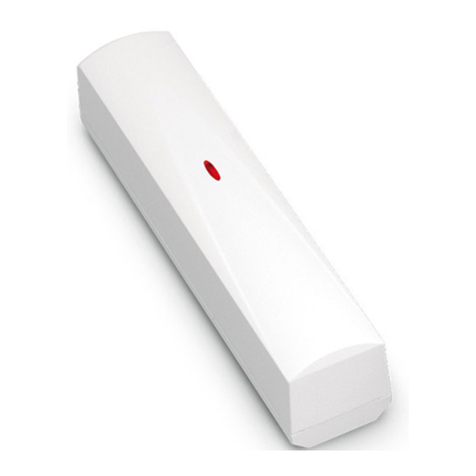
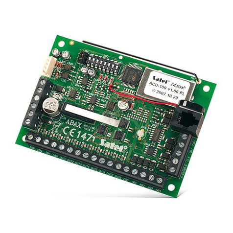
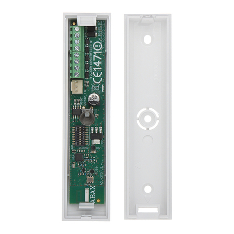
Satel RX1K User manual

- 1 -
RX1K
RADIO CONTROLLER
®
Program Version 1.1
rx1k_e 06/04
The one-channel RX1K radio controller has been designed for application in the security systems, where
it can serve control functions for arming partitions, and bypassing partitions or detectors, or even panic
buttons. Owing to its expanded configuration options,it can be successfully used in all situations
requiring the wireless control.
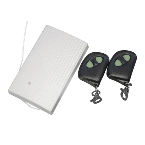
The radio controller is fitted with an electromagnetic relay which provides direct control of the electric
equipment operation. To perform the control function (as transmitters), two- or four-button remote
controls are designed. High resistance of the remote controls to environmental changes ensures a stable
performance and a high comfort of the controller use. The construction, based on the Microchip
Technology Inc. component parts, which use the dynamically changed KEELOQ® code for the
transmission between transmitter and receiver, ensures both the safety of use and the resistance to
spurious control signals coming from other equipment. The one-channel controller is capable of working
together with 40 remote controls. It can only handle the SATEL remote controls.
Interfacing with the security systems is facilitated by the inputs informing of the system status, which
make for an easy arrangement of the signaling of arming/disarming and clearing alarm.
WARNINGS
The control panel main board contains electronic components sensitive to electric charges. Prior to
installation, these charges must be removed. During installation, avoid touching any elements on the
control panel main board.
Making any construction changes or unauthorized repairs is prohibited. This applies, in particular, to
modification of assemblies and components.
It is recommended that in the remote controls the producer’s required battery should be used.
CAUTION! The old batteries must not be thrown away, but disposed of as required by the
existing regulations (European Directives 91/157/EEC and 83/86/EEC).
HOOKUP DESCRIPTION
Figure 1. View of the one-channel controller board.
DESCRIPTION OF TERMINALS:
AR – input of signal indicating the security system armed mode
AL – alarm signal input
LV – output of remote control low battery signal (OC)
SS – signaling device control output (OC)
+12V – supply voltage input (direct voltage 9 to 16V)
AR AL. LV SS+12V COM C NC NO
TMP
D1 PROGRAM
ANTENNA
RECEIVER
ANTI-TAMPERING
CONTACT
ABC
JUMPER

- 2 -
COM – ground
C– common terminal of relay
NC – normally-closed terminal of relay
NO – normally-open terminal of relay
TMP – anti-tampering contact terminals
The D1 (two-color) LED is the module operation indicator, which helps in programming the controller
parameters. In normal condition, the color of its light is green, changing into red when a signal is
received by the controller from the transmitter (remote control). The blinking red light means that the
remote control battery is low.
The LV output becomes active when remote control low battery condition is found by the controller, and
remains on until a remote control with good battery is used. It can serve e.g. to report security system
troubles.
The PROGRAM button is intended for programming the remote controls to work together with the
controller, and for programming the monostable switching time of the relay.
The three pins (ABC) situated at the PROGRAM button are used for setting the relay operation mode.
PROGRAMMING OF REMOTE CONTROLS
The controller only serves the remote controls if entered into its memory by the following procedure:
1. Press the PROGRAM button – the LED will start blinking in green.
2. Press the remote control button – the LED will change its color into (blinking) red.
3. Press again the same remote control button – the LED will light in steady green color – the remote
control has been entered into the memory.
If the memory is already full or if the remote control is incorrect (made by another manufacturer), the first
depression of the remote control button will make the controller return to its normal condition.
The one-channel controller is operated by each of the remote control buttons.
Clearing the remote control from the controller memory is only possible by erasing the whole
memory contents. In order to do so, press and hold down the PROGRAM button for about
3 seconds (the LED will blink in red), release the button for about 1 second, then press it again
and hold down for 3 seconds. The LED will start blinking in red and then, when the memory is
cleared, it will return to the green color. The controller is now ready for programming the remote
controls.
IMPORTANT:
- When closing the housing, be particularly careful so as not to depress the programming buttons with
cables .
- The lifetime of remote control batteries depends on how often they are in use. The batteries must be
periodically checked (e.g. by noting how the D1 LED lights when the controller button is depressed,
or by using the controller LV output) and replaced with new ones.
SETTING THE RELAY OPERATING MODE
The relay can work in one of the three modes (selected by means of jumpers and ABC pins):
1. Bistable (all pins open) – each depression of the remote control button changes the relay status to
the opposite one.
2. Monostable (pins A and B closed) – the relay is activated for a determined time.
3. Pulse (pins B and C closed) – the relay is active as long as the remote control button is depressed.
The time of monostable switchover is set in the following way (by default and after clearing the remote
controls, the time is set to 5 seconds and can be changed within the range from 1 to 255 seconds):
- Press the PROGRAM button twice – the LED will go out.
- Press the remote control button – the LED will start blinking alternately in green and red.
- Measure the programmed time and press again the remote control button – the LED will light in
steady green color.
- 3 -
INTERFACING WITH THE SECURITY SYSTEM
When signals informing of the security system armed mode and alarm (time of alarm to be cleared) are
fed to the controller inputs, the function of generating appropriate signals on the SS output is activated.
The armed mode (AR) and the alarm (AL) are indicated by grounded input. The signaling is effected by
grounding the SS output for the time of impulse (0.16 second; current-carrying capacity 0.5A).
- One signal – arming.
- Two signals – disarming.
- Four signals – disarming and clearing alarm.
The AR and AL inputs are monitored for 4 seconds after the remote control is used– which means the
AR input status must be changed within that time, or the SS output will not generate any signals. Thus,
arming or disarming performed from the keypad will generate no signals on the SS output of the
controller.
EXAMPLE:
Figure 2. Example of armed mode remote control in the SATEL CA-6 plus control panel
with indication of remote control use on the external signaling device.
In the above example, the panel armed mode is controlled by means of the remote control. The relay
works in the pulse mode (pins B and C shorted) and connects ground (0V) to the panel CTL input. In
order to arm or disarm the system, press and hold down the remote control button until you hear a beep
from the alarm signaling device.
The figure above shows also a simple way of providing a remote control low battery indicator.
+ SO -+ SA -SAB
Signaling device
SP-500
SPL-2010
SPL-2030
ANTI-TAMPERING
CIRCUIT
1kΩ
LOW BATTERY
INDICATOR
CBA
+12V
+12V
OUT4
OUT5
COM
AC AC COM OUT1 COM OUT2 COM OUT3COM+KPD DATA CLK CTL Z1 COM Z2 Z3 COM Z4 Z5 COM Z6
ALARM CONTROL PANEL CA-6 plus
RELAY
JUMPER
NO NC C COM+12V SS LV AL AR
TMP
D1

- 4 -
To implement the example, the following parameters must be programmed in the CA-6 plus panel:
OUT1 - Time alarm (+12V when the output is active);
OUT2 - Alarm to be cleared (+12V when the output is active);
OUT3 - Supply output (+12V);
OUT4 - Armed mode indicator (OC type output – program +12V when active)
OUT5 - Alarm to be cleared (OC type output – program +12V when active);
CTL - Arming/disarming one or both partitions (FS 125);
Z6 - 24H loud line (anti-tampering circuit).
The presented example shows just one of the many possible applications of the controller.
TECHNICAL DATA
Range in open area ................................................................................................................. up to 100m
(obstructions between transmitter and receiver will reduce the device operating range)
Number of controlled channels ............................................................................................................... 1
Power supply voltage ............................................................................................................ DC 9 to 16V
Current consumption, minimum ......................................................................................... approx. 13mA
Current consumption, maximum ......................................................................................... approx. 30mA
Max. switching current of relay contacts................................................................................1,25A/AC/DC
Current-carrying capacity of relay contacts ...............................................................................2A/AC/DC
Max. switching voltage of relay contacts.......................................................................150V DC/100V AC
Time control range in monostable mode ................................................................................... 1 do 255s
Current-carrying capacity of LV (OC) output ................................................................................... 50mA
Current-carrying capacity of SS (OC) output.................................................................................. 500mA
Working frequency ..................................................................................................... 433.92MHz±75kHz
Working temperature range ................................................................................................. -10 to +50 ºC
Dimensions:
Receiver ............................................................................................................................ 117x72x23mm
Remote control, two-channel................................................................................................ 50x35x11mm
Remote control, four-channel .............................................................................................. 55x37x16mm
Battery type:
For remote control, two-channel (P-2).......................................................................................... 27A 12V
For remote control, four-channel (P-4)..........................................................................................23A 12V
Latest EC declaration of conformity and product approval certificates can
be downloaded from our Web site www.satel.pl
SATEL sp. z o.o.
ul. Schuberta 79
80-172 Gdańsk
POLAND
tel. + 48 58 320 94 00
info@satel.pl
www.satel.pl
Table of contents
Other Satel Controllers manuals

Satel
Satel MICRA VERSA-MCU User manual

Satel
Satel INT-CR User manual

Satel
Satel MTX-300 User manual

Satel
Satel ABAX 2 ACU-220 User manual

Satel
Satel ACU-120 User manual

Satel
Satel ACU-270 User manual

Satel
Satel KNX-BSA12H User manual

Satel
Satel ACU-280 User manual

Satel
Satel ACU-220 User manual

Satel
Satel ASW-210 User manual

Satel
Satel ABAX 2 ACU-280 User manual

Satel
Satel VERSA-MCU User manual

Satel
Satel ASW-100 E User manual

Satel
Satel KNX-SA41 User manual

Satel
Satel RX-2K User manual

Satel
Satel KNX-BSA12L User manual

Satel
Satel ABAX 2 ACU-280 User manual

Satel
Satel RX-2K User manual

Satel
Satel KNX-DIM21 User manual

Satel
Satel KNX-SA41 User manual