27 Bank Street Meadowbank NSW 2114 Australia
Tel: +61 2 9809 0588 Fax: +61 2 9809 2446 email: sales@cs-technologies.com.au
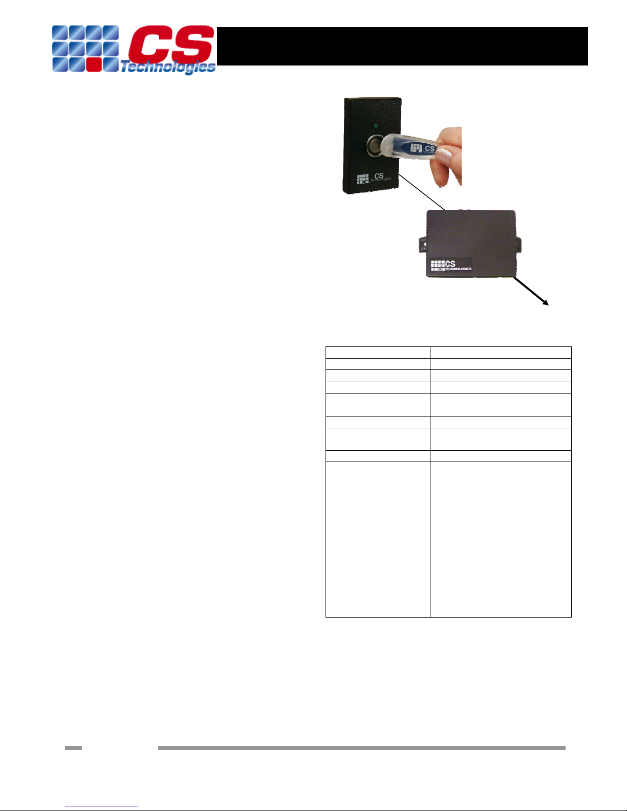
iKey Interface
Cable Types
Function Cable
Silicon Key reader to interface 4-core UTP (Cat 5 preferred). Up to 20m
Interface to security panel or host 7/0.20 6-core screened cable. Up to 100m
Installation Procedure
Mounting the converter:
The iKey interface should be mounted in a convenient
location. Removing the base of the box will release the circuit
board which can be terminated. To mount the box, make all
connections first then replace the base of the box and mount
the box using the two ‘bulkhead’ mounting tabs on the top and
bottom of the box.
Connecting the Silicon Key reader:
The reader has four wires. Two are for the touch probe, and
connect to the interface (black wire = GND, white wire =
IN1). The other two wires are for the LED. The red wire
connects to +5V and the blue wire connects to IN2.
Connecting to the host panel:
The output from the interface is either Wiegand (LK5 link
on), clock and data (LK5 link off) or RS232 (JP3 link on).
Ensure that the security panel and the converter have a
common reference by connecting GND on the converter to 0V
on the panel. Connect the converter +5V to the reader power
out +5V on the panel.
For a wiegand format output, IN3 = DATA0 and IN4 =
DATA1.
For a clock and data format output, IN3 = CLK and IN4 =
DATA.
For an RS232 format output, IN4 = TX
Many security panels or hosts also have the ability to drive a
LED on the reader. Connect the LED output on the panel to
IN2 on the controller (where the LED wire from the reader
terminates).
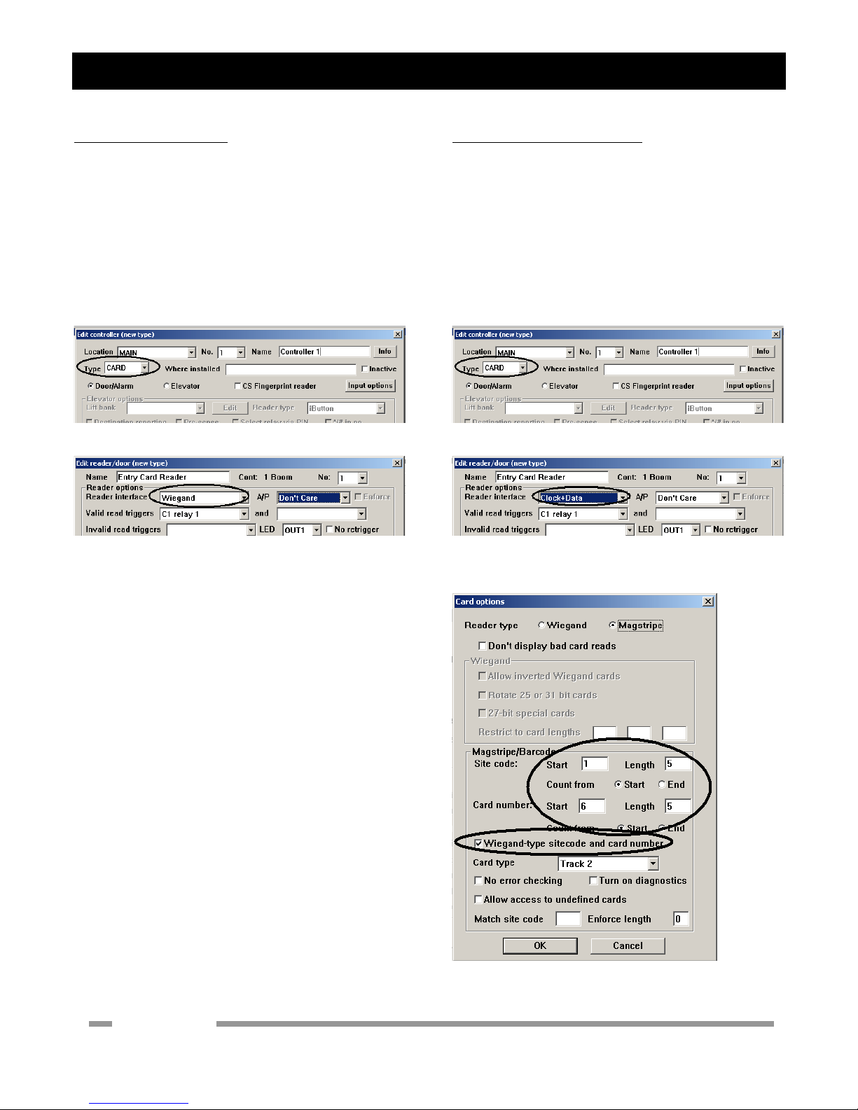
Configuring the interface:
a) Select the data format to be transmitted by the interface
by setting LK5 to ON for wiegand format, OFF for clock-
and-data format or JP3 ON for RS232 format.
b) [Only if not factory-set]. The internal reader ID must
be set by connecting a link at LK1 with JP3 removed.
When there is a link here the red LED on the controller
should flash quickly. Touching a valid CS Technologies
iKey to the reader will cause the internal ID to be set to
match the key, and the interface will beep very quickly
twice. Now the link can be removed and the reader will
recognise keys with that same internal ID.
Before powering up the interface board:
Unit installed in dry, secure location
Field wiring installed
Connections to security panel verified
Connections to Silicon Key reader verified
No short to earth on any input or output
After powering up the interface:
Controller beeps three times
LED1 (Power) on
LED2 (Heartbeat) flashing slowly
[Only if not factory-set]. Set the reader ID to match your
keys by putting a link on LK1 and removing JP3 link.
LED2 should flash faster, and touching a key will make
the interface beep twice. Then remove the LK1 link. Only
keys with that valid reader ID will work at the reader.
Operational check:
Present a silicon key at the reader. The serial number
should be transmitted in the format selected by LK5/JP3.
Verify that a read has occurred on the host panel.
With the LED drive disconnected from the security panel,
the interface will drive the LED on the silicon key.
Operation of the reader LED indicates the following
conditions:
a) When a key with the same reader ID is presented
at the reader the reader LED will flash twice.
b) When a key with a different reader ID is
presented at the reader the reader LED will flash
3 times
c) When a key which is not in any recognised
format is presented at the reader the reader LED
will flash once.
The system will also beep quickly twice for any valid
read, or once for a key which is not programmed or has
the wrong internal ID.
Troubleshooting:
Check power connection to controller polarity and
voltage
Check reader cabling.
Check LK5/JP3 link setting is correct
Check for wiegand that IN3 is connected to the DATA0
input on the panel, and IN4 is connected to the DATA1
input on the panel.
SigningOff
iKey Interface installed and all checks completed: Date:
Location: