CSI Controls RK Series User manual
RK Series™
Serious Products for Serious Contractors!
Float Systems Manual

Page 2
RK Series™
Table of Contents
About the RK Series Float Systems....................................................Page 4
Float System Installation Instructions...............................................Pages 5-7
Step 1: Installing the Floats
Step 2: Installing the Controller
Typical Float System Installation Diagram
Understanding the Float System........................................................Page 8
Subdoor Control Center
Float Indication Status Lights
Float System Features.........................................................................Pages 9 - 10
Hand Run Buttons
Blown Fuse Indicators
Audible Alarm Circuitry
Alternation and Lag Delay
Special Options
Redundant Off Float
Auxiliary Alarm Contact
RK “E Series”
DDCs and DIBs
Understanding the RK “E Series” Float System...............................Page 11
Subdoor Control Center
Hand-Off-Auto Switch
Digital Display Center (DDC)...............................................................Page 12 - 15
Installation
Display Menu
User Settings Menu
Level Control Options Menu
Time Dosing Options Menu
DDC Flow Chart

Page 3
Digital Interface Board (DIB)............................................................
Installation
Display Menu
User Settings Menu
Level Control Options Menu
Time Dosing Options Menu
Telemetry Menu
Alarm History Menu
Auxiliary Inputs
Flash Codes
FCC Information
DIB Flow Chart
Float System Troubleshooting..........................................................
Enclosure Dimensions........................................................................
Field Wiring Connections..................................................................
Terminal Strip With All Available Options
Determining Your RK Model Number
Float System Specifications..............................................................
Pages 16 - 22
Pages 23 - 24
Page 25
Page 26
Page 27
RK Series™
The Control Panel
Page 4
About the RK Series Float Systems
The RK Series float system is an innovative approach to today’s level
control requirements and offers many of the most requested items as
standard features such as lockable latches, a flashing red alarm light, an
electronic horn, and the innovative "Touch-To-Silence" pad all in a NEMA 4X
enclosure. Through the use of a standard subdoor and raised backpanel, the
RK Series is able to house common control panel features such as circuit
breakers, start components, contactors, and a terminal strip. The RK Series
also offers an exclusive control circuit board with float indication lights
conveniently located on the subdoor that allow the user to see the status of
each float.
Available in : Simplex or Duplex
Single Phase to Three Phase
Floats
-3 for simplex
-4 for duplex
Standard Float Systems Include:
RK Series™

Page 5
Float System Installation Instructions
Step 1: Installing the Floats
Installation Using the 2” PVC Mounting Bracket
Install the PVC mounting bracket to the side of the
tank and suspend a length of 2” PVC pipe from the
bracket. This allows the installer to mount the floats
the same as they would to the discharge pipe.
Installation Using the Float Mounting Bracket
Mount the bracket to the side of the tank and then
install the floats and weights into the cord snubbers.
Warning: 1. Do not install a float switch in direct line of incoming liquid
2. Make sure you leave at least 3.5 inches of tether length
between the actual float and the clamping device to allow
the float to tip properly.
The installer can tie wrap the floats to the pump discharge pipe at the
appropriate levels using a heavy duty tie wrap or a clamp designed for that
purpose.
Basic Float Installation
Warning: In critical applications where a failure could cause property
damage, a separate backup high water alarm should be used.
RK Series™

Page 6
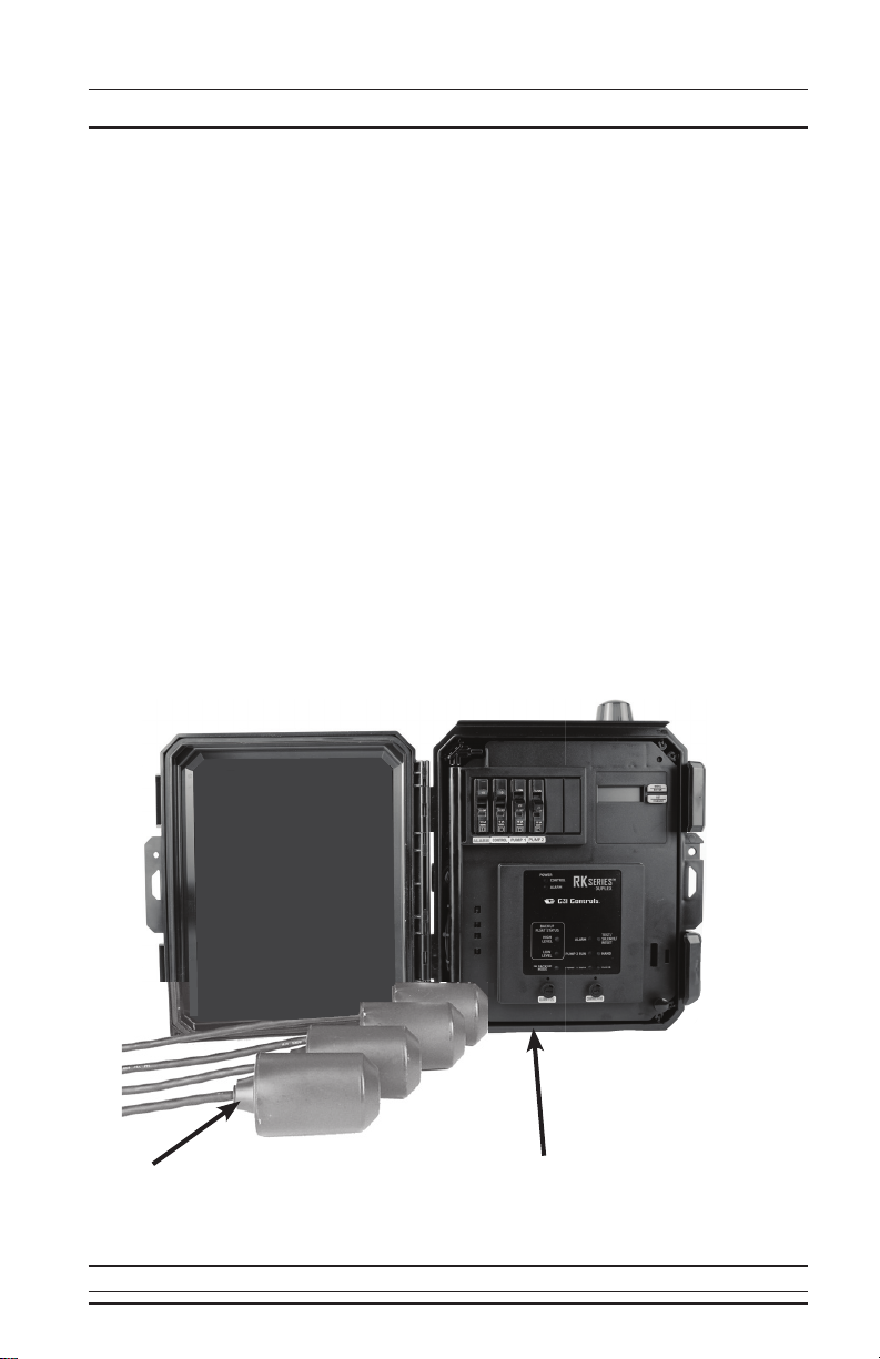
Step 2: Installing the Controller
1. Determine a mounting location for the panel.
2. Determine the location of the conduit(s) coming into the panel.
3. Drill holes in the panel for conduit entry.
4. Mount the panel using the provided mounting feet.
5. Bring the float wires and power wires into the panel through the
conduit.
6. Wire the panel according to the schematic included in the panel.
7. Check installation by turning power on and manually tipping the
floats or running up the water level to test for proper installation.
8. Test the unit periodically to ensure proper operation.
Float System Installation Instructions
RK Series™

Page 7
Float System Installation Instructions
Typical Float System Installation Diagram
RK Series™
Note: Care should be taken to ensure
that sewage gases are not allowed
to enter the control panel by using
an approved gas sealing means!
(Damage caused by sewage gas is
not covered by warranty).

Page 8
Understanding the Float System
Subdoor Control Center
Float indication lights show the status of the floats in the basin. If a float
is tipped closed, the corresponding LED will be lit. If the floats tip out of
sequence it will cause the float indication lights to show an error. If a higher
float comes on before the next lowest float, the LED of the lower float will
flash indicating a problem. For example, if the “Lead Pump On” float hangs up
and the water level comes down to the “Pumps Off” float level, the “Pumps
Off” float will tip down. The “Pumps Off” LED will then flash while the “Lead
Pump On” LED remains on. However, the error indication will be automatically
cleared next time the floats sequence in the proper order. Another example
would occur when the “Pumps Off” float fails to close when it tips up. When
the “Lead Pump On” float tips up, the “Pumps Off” LED will then flash while
the “Lead Pump On” LED remains on. Even though the error indication is the
same there could be two causes for the error. The first cause being a hung up
float, and the second cause being a float failure. These lights help to assist in
troubleshooting float errors and station problems.
Float Indication Status Lights
If you need any additional help please call the factory for technical
assistance: 1-800-746-6287
Control Circuit
Power Light
"High Level"
Light
"Lag Pump
On" Light
"Lead Pump
On" Light
Alarm Light
"Pumps Off"
Light
Pump Run Lights
Hand Run
Pushbuttons
Test/Silence
Pushbutton
Alarm Circuit
Power Light
RK Series™

Page 9
Float System Features
Hand Run Buttons
RK panels include push-to-run (HAND) pushbuttons for the motor starters
output and a push-to-test (TEST) pushbutton for the alarm output accessible
on the subdoor. The push-to-run (HAND) pushbuttons toggle their respective
outputs off and on each time pushed under normal operation. However, to
protect the pumps should the sump go below the "Pump(s) Off" float, the
HAND pushbuttons revert to momentary contact and must be held down
to maintain its respective output on. This is a safety feature that keeps the
pumps from running dry.
Audible Alarm Circuitry
RK panels come standard with an audible piezo alarm (95 db +/-) and the
exclusive side mounted “Touch-To-Silence” pad (patents pending). With this
feature the user is able to silence the audible by simply touching the decal on
the side of the enclosure.
Blown Fuse Indicators
These lights are located above the fuses on the subdoor. If a fuse is blown,
the indicator above the blown fuse will light up and the power light on the
subdoor control center for that circuit will be off. However, if the power light
is off and the blown fuse light is not lit then that circuit is not getting any
power.
Alternation and Lag Delay (Duplex Controllers Only)
On the duplex controller the float indications are labeled "Lead Pump" and
"Lag Pump" because there is a built in alternator in the controller. The
alternator cycles which pump is the lead pump after each pump run cycle.
The non-adjustable delay causes the lag pump to wait ten seconds before
turning on after the lead pump has turned on. This is useful during a power
outage when the liquid level may reach the lag pump setting. The lead
pump will turn on when power is restored and the lag pump will turn on ten
seconds later.
RK Series™

Page 10
Float System Features
Redundant Off Float
The redundant off float option reassures that the pump(s) will not run dry. If
your panel has this option the terminal strip will include numbers 7 & 8. To
use the redundant off option, connect a normally open float switch to these
terminals, otherwise install a jumper across terminals 7 & 8 if you do not
wish to use this feature. When the float is in the open position the pumps will
not be able to run except by using the hand run push buttons in momentary
contact mode.
Note: “Hand Run Buttons” (page 8) describes momentary contact mode.
Special Options
Auxiliary Alarm Contact
If your panel has the Auxiliary Alarm Contact option then the terminal strip
will include the numbers 17 & 18. This option offers a dry contact that closes
during a high level alarm condition then opens when the alarm goes away or
when the panel is silenced.
DDCs and DIBS
Every RK Series panel has a removable faceplate on the subdoor to add
either a Digital Display Center (DDC) or a Digital Interface Board (DIB).
Upgrading to one of these display options allows the user to access more
features.
DDC Operation Manual - Page 11
DIB Operation Manual - Page 15
RK “E Series”
The RK “E Series” offers basic features including 3-float operation (simplex
only), "Touch-To-Silence" pad, an audible alarm, and flashing alarm light in a
NEMA 4X enclosure. It is an economical solution for your pump control needs.
Understanding the
“E Series” Float System -Page 10
RK Series™
Page 11
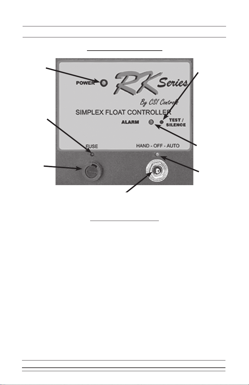
Understanding the “E Series” Float System
Pump Run
Light
Test/Silence
Pushbutton
Power Light
User Safe Fuse
Hand-Off-Auto
Switch
Hand-Off-Auto Switch
The Hand-Off-Auto switch is located on the front of the subdoor for control
of the pump state. In the “Auto” position, the level control circuit will control
the pump. In the “Hand” position, the pump will be turned on, and in the “Off”
position the pump will be disabled from running.
Note 1: When there is a fuse blown condition on a RK “E Series”
controller the “blown fuse indicator” will light and the “power
light” will continue to be dimly lit.
Blown Fuse
Indicator
Alarm Light
If you need any additional help please call the factory for technical
assistance: 1-800-746-6287
Subdoor Control Center
Note 2: Since the "E Series" is an economical version of the float
system, it does not support certain features. Features not
available in the “E Series” panels are Alternation (simplex
control only), Hand Run Buttons, Float Status Lights, Redundant
Off Float Option, and the Auxiliary Alarm Contact option.
RK Series™
Page 12
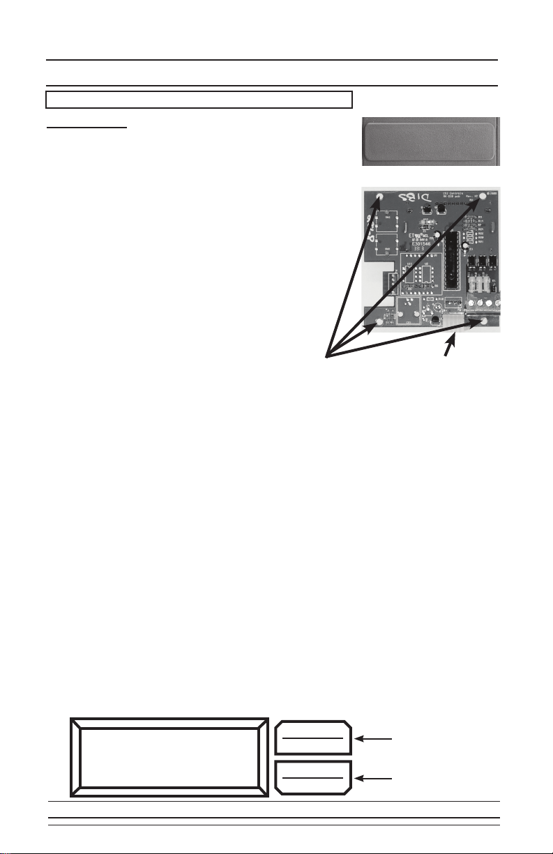
Digital Display Center (DDC)
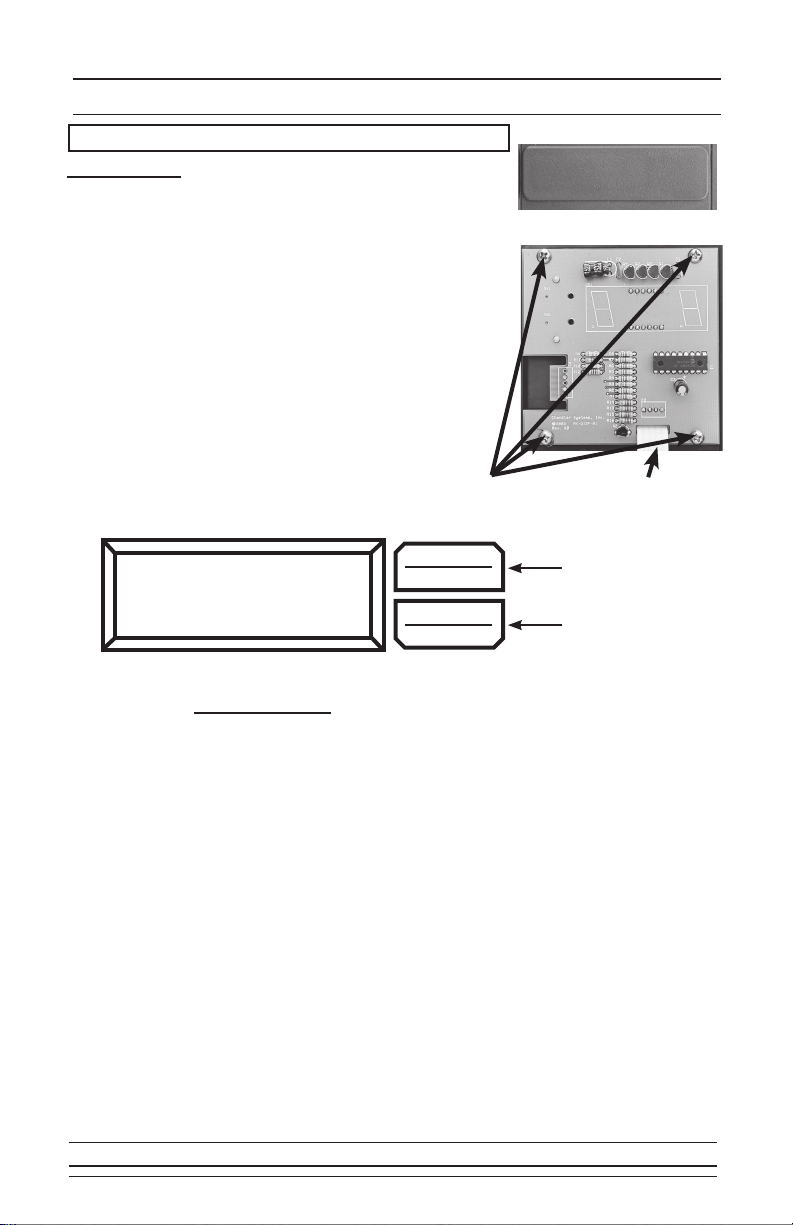
Installation
To install the DDC, remove the faceplate from above the
control center on the subdoor and insert the DDC module
from the back of the subdoor. Next, screw in the four
corner screws. With the power off, attach the ribbon from
the DDC module to the control board. After everything is
installed, turn the power on. It may take up to 10 seconds
for the circuit board to complete the program update.
Once the circuit board has completed the program
update, normal operation will begin.
Note: RKE boards cannot update through the DDC.
Display Menu
Press Menu/Enter Button to change between menu
fields
Et. # - (Elapsed Time, # is Pump number (1 or 2)):
Reads out the total elapsed run time of the corresponding pump.
Press Set/Change button to alternate between
hours and minutes & seconds
CC.# - (Cycle Counter, # is Pump number (1 or 2)):
Reads out the number of cycles the corresponding pump has
run. (Max Value: 9999)
F1tr - (Field 1 Timer, Time Dose DDCs only):
Reads out the remaining time in the current time cycle. If the
pump(s) are running then it indicates the time remaining until the
pump(s) shut off. If the pump(s) are off then it indicates time
remaining until the pump(s) are enabled to run again.
Installation Screws
Back of DDC Module
Connecting Ribbon
Menu/Enter
Button
Set/Change
Button
dEPH MENU
ENTER
SET
CHANGE
Make sure power is OFF before installing DDC!
RK Series™
Removable Face Plate
Installation Screws

Page 13
Digital Display Center (DDC)
User Settings Menu
Press and hold Menu/Enter Button for 3 seconds while in the Display Menu to
enter into this menu. Press the Menu/Enter Button to change between menu fields.
LCOP - (Level Control Options Menu):
Press Set/Change button to enter into this submenu.
tDOP - (Time Dosing Options Menu, Time Dose DDCs only):
Press Set/Change button to enter into this submenu.
Level Control Options Menu
LSS - (Lead Selection Setting, Duplex Panels Only):
Display will alternate showing “LSS” and the current value.
Press Set/Change button to change this field.
Possible Settings:
0 = Alternate Between Pumps
1 = Pump #1 Always is Lead Pump
2 = Pump #2 Always is Lead Pump
r CC - (Reset Cycle Counter(s))
Display will alternate showing “r CC” and the value “0.”
Press Set/Change button to change this field.
Possible Settings:
0 = Do Not Reset Cycle Counter(s)
1 = Reset Cycle Counter(s) to 0
RK Series™

Page 14
Digital Display Center (DDC)
F1t1 - (Field 1 Time 1 (Pump Enable Time Setting))
Display will alternate showing “F1t1” and the current value. Time shown
is in [Minutes : Seconds] (Maximum time setting is 99:59)
Press Set/Change button to change this field.
F1t2 - (Field 1 Time 2 (Pump Disable Time Setting))
Display will alternate showing “F1t2” and the current value. Time shown
is in [Hours : Minutes] (Maximum time setting is 99:59)
Press Set/Change button to change this field.
ALOr - (Alarm / Override Function):
Display will alternate showing “ALOr” and the current value.
Press Set/Change button to change this field.
Possible Settings, Simplex:
(What the High Level input will do)
0 = Override the Pump Disable Timer and Alarm with selected
Time Delay (see HLtd setting). A warning will sound and
flash the alarm light to indicate the panel is in Override
mode. This can be silenced. It will be cleared after the
Disable Timer times out.
1 = Only Override the Pump Disable Timer without any alarms.
2 = Only Sound High Level Alarm without any delays.
Possible Settings, Duplex:
(What the Lag (override) input will do)
0 = Override Pump Disable Timer. A warning will sound and
flash the alarm light to indicate the panel is in Override
mode. This can be silenced. It will be cleared after the
Disable timer times out.
1 = Override the Pump Disable Timer. No warning will sound.
2 = Override function is disabled. Lag float input is ignored.
HLtd - (High Level Time Delay, Simplex Panels Only):
Display will alternate showing “HLtd” and the current value. The High
Level Alarm will delay according to the set time. If the fluid level is
above the High Level input for this length of time without interruption,
the alarm will begin to sound. Time shown is in [Minutes : Seconds]
(Maximum time setting is 99:59)
Press Set/Change button to change this field.
Time Dosing Options Menu
RK Series™
Page 15
Digital Display Center (DDC)
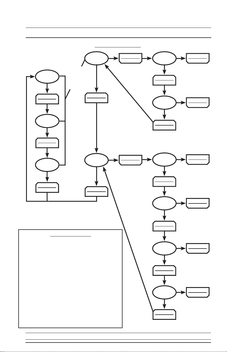
DDC Flow Chart
Digital Display Key
Et.# - Elapsed Run Time of Corresponding Pump
CC.# - Number of Cycles the Corresponding
Pump Has Run
F1tr - Field 1 Timer (Time Dose DDCs Only)
LCOP - Level Control Options Menu
tDOP - Time Dosing Options Menu (Time Dose
DDCs Only)
LSS - Lead Selection Setting (Duplex Panels
Only)
rCC - Reset Cycle Counters
F1t1 - Field 1 Time 1 (Pump Enable Setting)
[MIN:SEC]
F1t2 - Field 1 Time 2 (Pump Disable Setting)
[HR:MIN]
HLtd - High Level Delay (Simplex Panels Only)
[MIN:SEC]
MENU
ENTER
MENU
ENTER
MENU
ENTER
MENU
ENTER
MENU
ENTER
MENU
ENTER
MENU
ENTER
MENU
ENTER
MENU
ENTER
MENU
ENTER
MENU
ENTER
SET
CHANGE
SET
CHANGE
Et. #
HLtd
ALOr
F1t2
r CC
LSS
tDOP
LCOP
F1tr
CC. #
SET
CHANGE
F1t1 SET
CHANGE
SET
CHANGE
SET
CHANGE
SET
CHANGE
SET
CHANGE
Press
& Hold
Menu/
Enter
Button
Push to Change
Field
Push to Change
Field
Push to Change
Field
Push to Change
Field
Push to Change
Field
Push to Change
Field
RK Series™
Page 16
Digital Interface Board (DIB)
Installation
To install the DIB, remove the faceplate from above
the control center on the subdoor and insert the
DIB module from the back of the subdoor (be sure
to remove the protective film on the display before
installing). Next, screw in the four corner screws.
With the power off, attach the ribbon from the DIB
module to the control board. After everything is
installed, turn the power on. It may take up to 10
seconds for the circuit board to complete the program
update. Once the circuit board has completed the
program update, normal operation will begin. Once a
DIB has been installed, the panel will not work if the
DIB is removed.
Note: RKE boards are not compatible with the DIB.
Installation Screws
Back of DIB Module
Connecting Ribbon
Make sure power is OFF before installing DIB!
Menu Navigation
To advance to the next menu, press the “Menu/Enter” button. To go to the settings
menu from the display menu, push and hold “Menu/Enter” until you see the “Level
Cntrl Menu” appear on the LCD screen. When in the Settings Menu press “Menu/
Enter" to cycle through the fields, to select a submenu, press the “Set/Change”
button.
Editing Fields
To edit the setting currently being displayed on the screen, press the “Set/Change”
button. The value that is now being edited will begin to flash. To change this value,
press the “Set/Change” button. To move to the next edit digit, or to finish editing the
setting, press the “Menu/Enter” button.
Example
To Change Pump Alternation Features: (Duplex Systems Only)
From the Display Menu press and hold the “Menu/Enter” button until “Level Cntrl
Menu” appears on the LCD screen. Next press the “Set/Change” button to enter
into the Level Control submenu. The first field is “Lead Pump Set”. Press the “Set/
Change” button again to change this field. The field being edited will flash. Press the
“Set/Change” button to change the field and press the “Menu/Enter” button to accept
the setting.
Lead Pump Set
Alternate
Menu/Enter
Button
Set/Change
Button
MENU
ENTER
SET
CHANGE
RK Series™
Removable Face Plate

Page 17
Digital Interface Board (DIB)
Display Menu
Press Menu/Enter Button to change between menu fields.
Elapsed Time # - (# is Pump number (1 or 2)):
Reads out the total elapsed run time of the corresponding pump. (Max
Value 999999:59:59) Time shown is in the format of
[Hours:Minutes:Seconds]
Cycle Count # - (# is Pump number (1 or 2)):
Reads out the number of cycles the corresponding pump has run.
(Max Value: 999999)
Override Count - (Time Dose DIBs only):
Reads out the number of times the panel has gone into override mode.
(Max Value: 999999)
High Level Count :
Reads out the number of times the liquid level has reached high level.
(Max Value: 999999)
Field #1 Timer - (Time Dose DIBs only):
Reads out the remaining time in the current time cycle. If the pump(s)
are running then it indicates the time remaining until the pump(s) shut
off. If the pump(s) are off then it indicates time remaining until the
pump(s) may run again.
Active Alarm :
Reads out what alarm condition the panel is currently experiencing. If
there are no alarms, it will read “None.”
User Settings Menu
Press and hold Menu/Enter for 3 seconds while in the Display Menu to enter into
this menu. Press the Menu/Enter button to change between the following menu
fields.
Level Cntrl Menu - (Level Control Options Menu):
Press Set/Change button to enter into this submenu.
Time Dosing Menu - (Time Dosing Options Menu, Time Dose DIBs only):
Press Set/Change button to enter into this submenu.
Telemetry Menu - (Modem DIBs only):
Press Set/Change button to enter into this submenu.
Alarm History :
Press Set/Change button to enter into this submenu.
RK Series™

Page 18
Digital Interface Board (DIB)
Level Cntrl Menu - (Level Control Options Menu):
Lead Pump Set (Duplex Panels Only):
Press Set/Change button to change this field.
Possible Settings:
Alternate = Alternates which pump turns on at LEAD PUMP
input every time a pump runs.
Pump 1 is Lead = Pump #1 ALWAYS turns on at the LEAD PUMP
input and Pump #2 ALWAYS turns on at the LAG
PUMP input.
Pump 2 is Lead = Pump #2 ALWAYS turns on at the LEAD PUMP
input and Pump #1 ALWAYS turns on at the LAG
PUMP input.
Reset Cyc Cnt # - This is the cycle count that can be viewed in the
Display Menu (Reset Cycle Counter to zero, # is pump number (1 or 2)
Possible Settings:
Do Not Reset = Cycle Counter will not reset
Reset Counter = Cycle Counter will reset to 0
Reset ETM # - This is the Elapsed time that can be viewed in the Display Menu
(Reset Elapsed Time to zero, # is pump number (1 or 2)
Press Set/Change button to change this field.
Possible Settings:
Reset Counter = Elapsed Time will reset to 0
Do Not Reset = Elapsed Time will not reset
RK Series™

Page 19
Digital Interface Board (DIB)
Time Dosing Options Menu (Time Dose Versions Only)
Pump 1 Time On - (Pump Enable Time Setting) This is the amount of time
the pump will be enabled to run once the level reaches the PUMP ON
(simplex) or LEAD PUMP ON (duplex) input. Note: If the level reaches the
PUMP OFF input before time expires, the pump will shut off and the Pump
Disable time will begin.
Time shown is in [Minutes:Seconds] (Maximum time setting is 99:59)
Press Set/Change button to change this field.
Pump 1 Time Off - (Pump Disable Time Setting) This is the amount of time
the pump must wait after it completes a run cycle before it may run again.
Note: If the level reaches the override (lag) input, the pump will begin to
run regardless of Pump Disable Time.
Time shown is in [Hours:Minutes] (Maximum time setting is 99:59)
To disable Time Dosing, set this field to 00:00.
Press Set/Change button to change this field.
Pump 1 Ovrrid On - (Pump Enable Time Setting for Override) This is the
amount of time the pump will be enabled to run once the level reaches the
override input at which time the system enters Override Time Dosing
mode.
Time shown is in [Minutes:Seconds] (Maximum time setting is 99:59)
Press Set/Change button to change this field.
Pump 1 Ovrrid Off - (Pump Disable Time Setting for Override) This is the
amount of time the pump must wait after it completes an Override run cycle
before it may run again. Note: The pump will continue to cycle in override
time dosing mode until the level is below the PUMP ON input when the
Override Pump Disable Time expires.
Time shown is in [Hours:Minutes] (Maximum time setting is 99:59)
Press Set/Change button to change this field.
Pump 2 Time On - (Pump Enable Time Setting)
See “Pump 1 Time On” Description
Time shown is in [Minutes:Seconds] (Maximum time setting is 99:59)
Press Set/Change button to change this field.
Pump 2 Time Off - (Pump Disable Time Setting)
See “Pump 1 Time Off” Description
Time shown is in [Hours:Minutes] (Maximum time setting is 99:59)
To disable Time Dosing, set this field to 00:00.
Press Set/Change button to change this field.
RK Series™

Page 20
Digital Interface Board (DIB)
Time Dosing Options Menu (Continued)
Pump 2 Ovrrid On - (Pump Enable Time Setting for Override)
See “Pump 1 Ovrrid On” Description
Time shown is in [Minutes:Seconds] (Maximum time setting is 99:59)
Press Set/Change button to change this field.
Pump 2 Ovrrid Off - (Pump Disable Time Setting for Override)
See “Pump 1 Ovrrid Off” Description
Time shown is in [Hours:Minutes] (Maximum time setting is 99:59)
Press Set/Change button to change this field.
Alarm/Override - This setting controls 3 functions of Time Dosing:
Override: When the basin level reaches the Override float (High Level
float on simplex, Lag float on duplex), the panel will override the
Off Timer, and run the pump(s) using the override On and Off times.
Override Warning: When an override occurs, the panel will sound an Override
Warning Alarm, to signal that an override event is occurring.
High Level Alarm: When the basin level reaches the High Level float, the
panel will sound a High Level Alarm, to signal that the liquid level is
much higher than expected.
Press Set/Change button to change this field.
Setting Override Override Warning High Level Alarm
Override w/ Alarms ON ON ON
Override-No Warning ON OFF ON
Overide-No Alarms ON OFF OFF
Alarm-No Override OFF OFF ON
High Level Delay - (High Level Time Delay, Simplex Panels Only):
The High Level Alarm will delay according to the set time. If the fluid level is
above the High Level float for this length of time without interruption the
alarm will begin to sound.
Time shown is in [Minutes:Seconds] (Maximum time setting is 99:59)
Press Set/Change button to change this field.
Number of Fields - (Duplex Panels Only):
The Time Dosing operation can be set up for “One Field” or “Two Fields.”
- When set to “Two Fields” each pump will be able to run as soon as its
corresponding Off Timer is complete. During override the two pumps
may run at the same time.
- When set to “One Field” each pump will only be able to run when the Off
Timer for both pumps is complete. The two pumps will never run at the
same time.
RK Series™
This manual suits for next models
1
Table of contents


