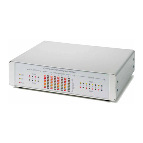
CL44
Technicial Specifications
Input
XLR ..........................................................................................................10K Ohms (Balanced)
1/4” TRS .................................................10K Ohms (Unbalanced) Ring or Tip Based on Flip Switch
Output
XLR............................................................................................................51 Ohms (Balanced)
1/4” TRS ...................................................51 Ohms (Unbalanced) Ring or Tip Based on Flip Switch
Insert/Sidechain (+4/-10 Based on Switch)
Tip = Return ..........................................................................................10K Ohms (Unbalanced)
Ring = Send.............................................................................................51 Ohms (Unbalanced)
Sleeve = Ground
Panel Controls
Low Cut Filter............................................................................................................20Hz-8kHz
Threshold......................................................................................................+15dBu to –40dBu
Ratio.......................................................................................................................1:1 to 20:1
Gain .................................................................................................................-20dB to +20dB
Compand ...............................................................................................................0% to 100%
Attack ..............................................................................................................01mS to 500mS
Release .....................................................................................................................01S to 3S
Limit........................................................................................................-10dBu to 24dBu (Off)
Optical Mode Switch
Link 1-2 and 3-4 Switch
Auto Switch
Bypass Switch
Performance
THD + Noise ..............................................................................................0.01% (0dBu output)
Signal To Noise...............................................................................................................>90dB
Gain Reduction Meters
LED...................................................................................................................-0.5dB to-24dB
Physical
Weight............................................................................................................................10lbs.
Dimensions..............................................................................................19” W x 7” H x 1.75” D
Chassis ............................................................................................................................Steel
Panel .............................................................................................................Painted Aluminum
Power Supply
Type...................................................................................................................Internal Linear
Input ..........................................................................100/120/220/240VAC (Factory Configured)
Power.........................................................................................................................24 Watts
What is DSP doing in the side-chain?
In modern compression, gating, limiting and dynamics processing technology, a copy of the audio signal is
processed to compute a precise amount of gain reduction or gain expansion of the original waveform (the side-
chain of the audio signal). This computation can be very complex as it involves frequency, time and amplitude
signal analysis. Traditionally, this process is performed using analog electronic functions such as rms/peak
detectors, rc time constant generators and general mathematical analog operations. However, once the side-
chain circuit is placed on the circuit board, it is fixed and cannot be easily changed or updated. This is where
digital signal processing (DSP) of the side-chain signal creates an enormous advantage over traditional systems.
Being software based, the DSP side-chain can be programmed to apply multiple functions simultaneously such
as filtering, vintage compressor emulation, and special function processing. Of course every common function
of dynamics processing; threshold, ratio, attack, release, etc. is part of the software.
(DSP in the side-chain is not to be confused with inserting an outboard EQ or other device into the side-chain
of a traditional setup to achieve frequency dependent compression or gating. Having DSP in the side-chain
allows for this to be accomplished on-board with out the need for external devices.)
In the PreSonus DSP side-chain products, the audible audio signal is controlled using a very warm, wide dynamic
range (>130dB) analog VCA. The VCA is adjusted using the output of the DSP side-chain computations. This
creates a warm yet very fast dynamics control system that is unparalleled in the industry.
Analog VCA Output BufferInput Buffer
DSP Sidechain
Processor
Audio In Audio Out
