manuals.online logo
Brands
  1. Home
  2. •
  3. Brands
  4. •
  5. pizzato
  6. •
  7. Control Unit
  8. •
  9. pizzato CSAR05V024 User manual

pizzato CSAR05V024 User manual

Pizzato Elettrica Srl
via Torino, 1
36063 MAROSTICA (VI)
ITALY
e-mail: [email protected]
web site: www.pizzato.com
Phone: +39.0424.470.930
ZE FOG39A19-EU
4/12
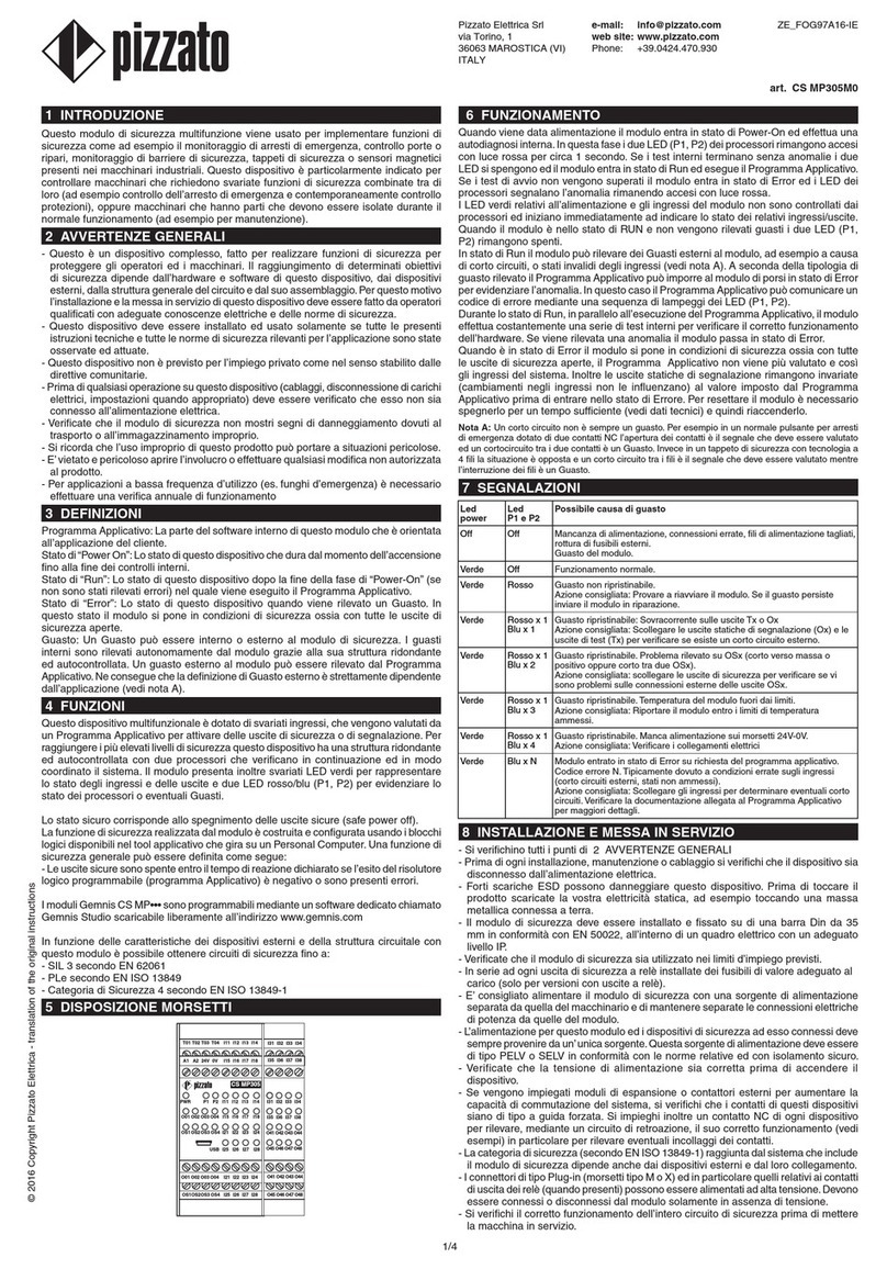
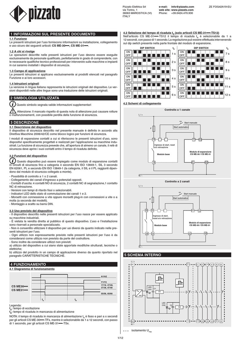
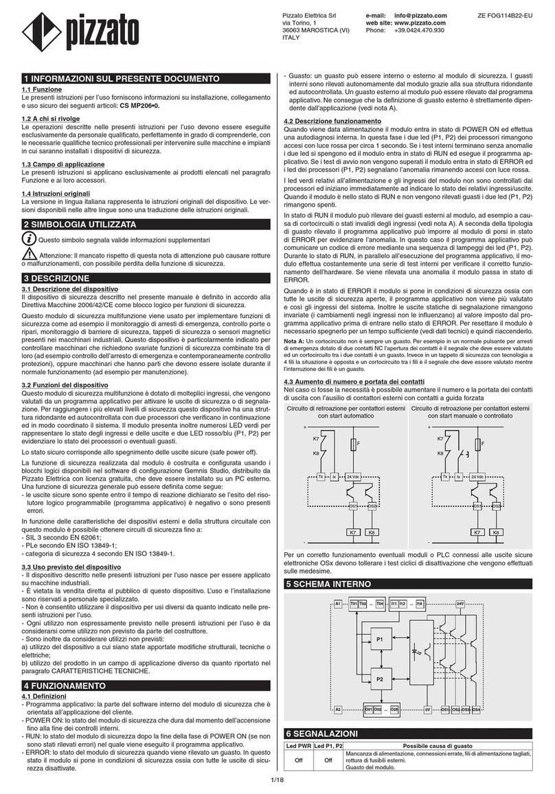
1 INFORMATION ON THIS DOCUMENT
1.1 Function
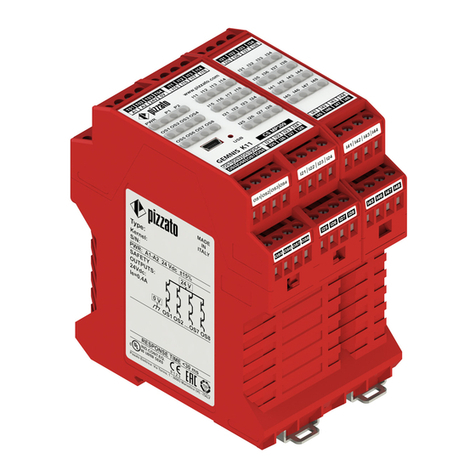
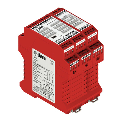
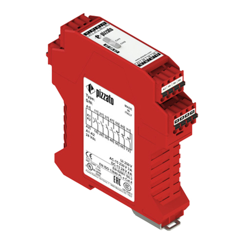
The present operating instructions provide information on installation, connection and
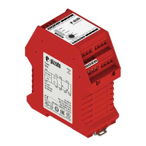
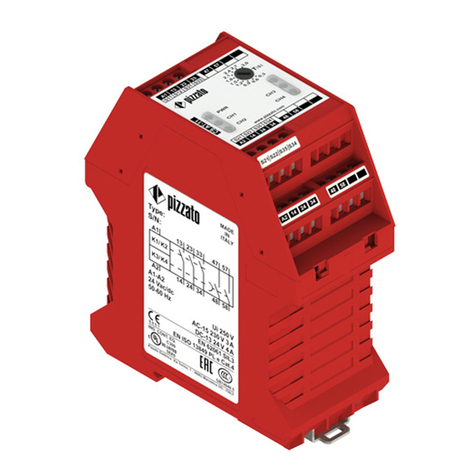
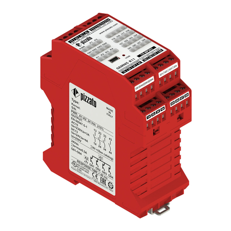
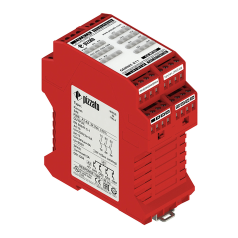
safe use for the following articles: CSAR-05••••,CSAR-06••••.
1.2 Target audience
The operations described in these operating instructions must be carried out by quali-
fied personnel only, who are fully capable of understanding them, and with the techni-
cal qualifications required for operating the machines and plants in which the safety
devices are to be installed.
1.3 Application field
These instructions apply exclusively to the products listed in paragraph Function, and
their accessories.
1.4 Original instructions
The Italian language version is the original set of instructions for the device. Versions
provided in other languages are translations of the original instructions.
2 SYMBOLS USED
This symbol indicates any relevant additional information
Attention: Any failure to observe this warning note can cause damage or mal-
function, including possible loss of the safety function.
3 DESCRIPTION
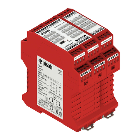
3.1 Device description
The safety device described in this manual is defined according to the Machinery
Directive 2006/42/EC as logic component for safety functions.
The safety modules to which these usage instructions refer are devices specifically
designed and manufactured for use on industrial machines. Upon opening of at least
one channel, the safety function ensures that the safety relays must open their output
contacts within the defined reaction time. The safety outputs of the module are ena-
bled only if the channels CH1 and CH2 are consistently closed and after activating
the START signal.
3.2 Device functions
This device is suitable for the following applications: as a module for emergency
stop, for end position monitoring with movable guards, for semiconductor outputs (e.g.,
light barriers) and for magnetic safety sensors in safety circuits up to category 4 acc. to
EN ISO 13849-1, up to SIL 3 acc. to EN 62061 and up to PL e acc. to EN ISO 13849-1.
- Input with 1 or 2 channels.
- The SIL 3 / PL e safety function is only available with the two redundant inputs
configuration.
- Output contacts: 3 NO safety contacts, 1 NC auxiliary contact.
- Automatic start, manual start (for CS AR-05•••• articles) or monitored start (for
CS AR-06•••• articles) possible.
With reference to the "automatic" operating mode, consider RES 1.2.3 of the
Machinery Directive 2006/42/EC: "For machinery functioning in automatic mode, the
starting of the machinery, restarting after a stoppage, or a change in operating condi-
tions may be possible without intervention, provided this does not lead to a hazardous
situation".
- Connection of input channels of opposite potentials.
- Can be connected to semiconductor outputs and to magnetic safety sensors.
- Short circuit detection function of the control elements by means of safety system
with self-monitoring and redundancy.
- LED indicators for switching state of the channels 1, 2 and for the power supply
voltage.
- Without muting input, no bridging of the safety function.
- In the event of a failure, the device switches to a safe state and deactivates the
safety output.
- Screw terminals or plug-in terminals with screw connections or spring terminals (de-
pending on the model).
- Snap-mounting on DIN rails.
3.3 Intended use of the device
- The device described in these operating instructions is designed to be applied on
industrial machines.
- The direct sale of this device to the public is prohibited. Installation and use must be
carried out by qualified personnel only.
- The use of the device for purposes other than those specified in these operating
instructions is prohibited.
- Any use other than as expressly specified in these operating instructions shall be
considered unintended by the manufacturer.
- Also considered unintended use:
a) using the device after having made structural, technical, or electrical modifications
to it;
b) using the product in a field of application other than as described in paragraph
TECHNICAL DATA.
4 OPERATION
4.1 Operating diagram
Automatic
start
(CSAR-05••••
only):
A1/A2
S11/S12 (+/S12)
S21/S22 (+/S52)
13/14, 23/24, 33/34
41/42
tCtAtR1
tR1 tCtAtR
tA
Monitored
start
(CSAR-06••••
only):
S12/S34 (START)
tAtR1
tR1
tAtR
tMIN tA
A1/A2
S11/S12 (+/S12)
S21/S22 (+/S52)
13/14, 23/24, 33/34
41/42
Manual start
(CSAR-05••••
only):
S12/S34 (START)
tAtR1
tR1 tAtR
tMIN
A1/A2
S11/S12 (+/S12)
S21/S22 (+/S52)
13/14, 23/24, 33/34
41/42
Legend:
tMIN:Min. duration of start impulse
tC:Simultaneity time
tA:Response time
tR1:Release time
tR:Release time in absence of power
supply
Notes: The configurations with one channel are obtained taking into consideration the
S11/S12 (+/S12) input only. In this case it is necessary to consider time tR1 referred to
input S11/S12 (+/S12), time tRreferred to the supply, time tAreferred to input S11/S12
(+/S12) and to the start, and time tMIN referred to the start.
4.2 Wiring diagrams
Emergency stop circuits
Input configuration with manual start
(CS AR-05••••) - 1 channel
Input configuration with manual start
(CS AR-05••••) - 2 channels
S12 S52
S21 S22
A1
S34 A2
S11
CS AR-05
L / +
N / -
S12 S52
S21 S22
A1
S34 A2
S11
CS AR-05
L / +
N / -
Semiconductor outputs
Input configuration with manual start
(CS AR-05••••) - 1 channel
Input configuration with manual start
(CS AR-05••••) - 2 channels
S12 S52
S21 S22
24 VDC
+
-
A1
S34 A2
OSSD
S11
CS AR-05
S12 S52
S21 S22
A1
S34 A2
OSSD1
S11
CS AR-05
OSSD2
+
-
24 VDC
S12
S34 S34
S12 Automaticstart(onlyforCSAR-05••••articles)
With regard to the indicated diagrams, short-circuit the start
button between the S12 and S34 terminals in order to acti-
vate the automatic start module.
Monitoredstart(onlyforCSAR-06••••articles)
Use the safety module with the circuit diagrams for manual
start.
5/12
Monitoring of movable guards and magnetic safety
sensors
The safety module can monitor emergency stop circuits,
control circuits for movable guards as well as magnetic
safety sensors. Replace the emergency stop contacts with
switch contacts or sensor contacts.
Magnetic sensors can be connected only in dual
channel configuration.
4.3 Increase of number and load capacity of contacts
If necessary the number and the load capacity of output contacts can be increased by
using external contactors with forcibly guided contacts.
Feedback circuit for external contactors
with automatic start
Feedback circuit for external contactors
with manual or monitored start
K3
K3
K4
K4
FF
N /-
L /+
S12 S34 13 23
14 24
K3
K3
K4
K4
FF
N /-
L /+
S12 S34 13 23
14 24
5 INTERNAL WIRING DIAGRAM
K1
K2
A1 S11 S12 S34 13 23 33 41
42
34
24
14
S22
S21
A2
S52
LED
CH1
LED
PWR
LED
CH2
L / +
N / -
LOGIC
CIRCUIT
LOGIC
CIRCUIT
6FAULTS
LED state Possible fault Recommended action
PWR CH1 CH2 - No power supply to the module.
- Wrong wiring.
- Power supply conductor/s cut.
- External fuse broken.
- Short circuit between channels.
- Internal module fault.
Check the wiring and
check the fuse.
If the fault persists,
replace the module.
PWR CH1 CH2 - Wrong wiring.
- Sticking of the contact of the emer-
gency stop button or of the control
device for movable guards connected
to S21-S22.
- Sticking of the start button contact
(monitored start).
- Internal module fault.
Check the wiring, the
start switch and the
emergency stop button/
control device for guards.
If the fault persists,
replace the module.
PWR CH1 CH2 - Sticking of the contact of the emer-
gency stop button or of the control
device for movable guards connected
to S11-S12.
- Internal module fault.
Check the wiring, the
start switch and the
emergency stop button/
control device for guards.
If the fault persists,
replace the module.
PWR CH1 CH2 - Wrong wiring.
- External contactors welded or expan-
sion module failure.
- Contactor/s cut.
- One or both contacts of the emer-
gency stop button or of the control
devices for movable guards are open.
- Activation cycle for manual or moni-
tored start (start impulse) missing or
both channels for the automatic start
closed.
- Internal module fault
Check the wiring, the
input channels and the
start configuration.
If the fault persists,
replace the module.
Legend: = led on; = led off.
7 INSTRUCTIONS FOR PROPER USE
7.1 Installation
Attention: Do not exceed the tightening torque of the terminal screws specified
in the present operating instructions.
Attention: Observe the wiring of the terminals: incorrect wiring can damage the
device which may result in loss of the safety function.
- Install only inside a cabinet with protection degree not less than IP54 according to
EN 60529.
- Always affix the device with the specific DIN rail adaptor acc. to EN 60715.
- Do not stress the device with bending and torsion.
- Do not modify or open the device for any reason.
- The device carries out an operator protection function. Any inadequate installation
or tampering can cause serious injuries and even death, property damage, and eco-
nomic losses.
- These devices must not be bypassed, removed or disabled in any other way.
- If the machine where the device is installed is used for a purpose other than that
specified, the device may not provide the operator with efficient protection.
- The safety category of the system (according to EN ISO 13849-1), including the
safety device, also depends on the external components connected to it and their
type.
- Before installation, make sure the device is not damaged in any part.
- Before commissioning, check the correct functioning of the module according to the
instructions of the operating diagrams (see paragraph OPERATION).
- Avoid excessive bending of connection cables in order to prevent any short circuits
or power failures.
- Do not paint or varnish the device.
- Do not drill the device.
- Do not use the device as a support or rest for other structures, such as raceways,
sliding guides or similar.
- Before commissioning, make sure that the entire machine (or system) complies with
all applicable standards and EMC directive requirements.
- The documents necessary for a correct installation and maintenance are always
available in the following languages: English, French, German and Italian.
- Should the installer be unable to fully understand the documents, the product must
not be installed and the necessary assistance may be requested from the manufac-
turer (see paragraph SUPPORT).
- Always attach the following instructions to the manual of the machine in which the
device is installed.
- These operating instructions must be kept available for consultation at any time and
for the whole period of use of the device.
7.2 Do not use in the following environments
- In environments where continual changes in temperature cause the formation of
condensation inside the device.
- In environments where the application causes the device to be subjected to strong
impacts or vibrations.
- In environments with the presence of explosive or flammable gases or dusts.
- In environments containing strongly aggressive chemicals, where the products used
coming into contact with the device may impair its physical or functional integrity.
7.3 Maintenance and functional tests
Attention: Do not disassemble or try to repair the device. In case of any malfunc-
tion or failure, replace the entire device.
- The device installer is responsible for establishing the sequence of functional tests
to which the device is to be subjected before the machine is started up and during
maintenance intervals.
- The sequence of the functional tests can vary depending on the machine complex-
ity and circuit diagram, therefore the functional test sequence detailed below is to be
considered as minimal and not exhaustive.
- Perform the following sequence of checks before the machine is commissioned and
at least once a year (or after a prolonged shutdown):
1) Check that the safety module housing is undamaged and in good condition. If the
housing is damaged, replace the entire device.
2) Check that all signalling LEDs are working.
3) Check that the electrical cables are firmly lodged inside the terminals and con-
nectors.
4) Check that during operation the module behaves according to the operating dia-
grams provided in section OPERATION.
- The device has been created for applications in dangerous environments, therefore
it has a limited service life. Although still functioning, after 20 years from the date
of manufacture the device must be replaced completely. The date of manufacture is
placed next to the product code (see paragraph MARKINGS).
7.4 Wiring
Attention: Do not install the safety module if voltage is present. Power the device
only when the electrical circuits have been completely realized according to the speci-
fications indicated in the OPERATION paragraph. The first time you start the machine
ensure that there are no people close to hazardous areas.
- Check that the supply voltage is correct before powering the device.
- Keep the charge within the values specified in the electrical operation categories.
- Only connect and disconnect the device when the power is off.
- When using plug-in-type terminal blocks, they may only be plugged in or unplugged
if no supply voltage is present.
- Discharge static electricity before handling the product by touching a metal mass
connected to earth. Any strong electrostatic discharge could damage the device.
- Power the safety module and the other devices connected to it from a single SELV
source and in accordance with the applicable standards (applies only to versions with
supply voltage 12 V and 24 V).
- It is recommended that the supply voltage of the safety module be electrically iso-
lated from the power section of the machine and the connection cables of the module
6/12
be laid separately from the power cables.
- Always connect the protection fuse (or equivalent device) in series with the power
supply for each device.
- Always connect the protection fuse (or equivalent device) in series to the safety
electrical contacts.
- During and after the installation do not pull the electrical cables connected to the
device. If excessive tension is applied to the cables, the device may be damaged.
7.5 Additional prescriptions for safety applications with operator protection
functions
Provided that all previous requirements for the devices are fulfilled, for installations
with operator protection function additional requirements must be observed.
- The utilization implies knowledge of and compliance with following standards:
EN ISO 13849-1, EN 62061, EN 60204-1, EN ISO 12100.
- In the risk analysis, take into account that in manual start mode a possible sticking of
the start button can lead to an immediate activation of the module.
- If expansion modules or external contactors are used, make sure that they have
forcibly guided contacts and connect in feedback an NC contact of each device.
7.6Limitsofuse
- Use the device following the instructions, complying with its operation limits and the
standards in force.
- The devices have specific application limits (min. and max. ambient temperature,
maximum currents, IP protection degree, etc.) These limitations are met by the device
only if considered individually and not as combined with each other.
- According to EU directives, this device is not intended for private use.
- The manufacturer’s liability is to be excluded in the following cases:
1) Use not conforming to the intended purpose.
2) Failure to adhere to these instructions or regulations in force.
3) Fitting operations not carried out by qualified and authorized personnel.
4) Omission of functional tests.
- For the cases listed below, before proceeding with the installation contact our as-
sistance service (see paragraph SUPPORT):
a) In nuclear power stations, trains, airplanes, cars, incinerators, medical devices or
any application where the safety of two or more persons depend on the correct opera-
tion of the device.
b) Applications not contemplated in this instruction manual.
8 MARKINGS
The outside of the device is provided with external marking positioned in a visible
place. Marking includes:
- Producer trademark
- Product code
- Batch number and date of manufacture. Example: CS1-123456 (A19). The last part
of the production batch refers to the month of manufacture (A = January, B = February,
etc.) as well as the year of manufacture (19 = 2019, 20 = 2020, etc.).
9 TECHNICAL DATA
9.1 Housing
Material: Polyamide PA 66, self-extinguishing V0 acc. to UL 94
Protection degree: IP40 (housing), IP20 (terminal strip)
Cable cross section: 0.2 … 2.5 mm2 (24 … 12 AWG)
Terminal tightening torque: 0.5 … 0.6 Nm
9.2 General data
SIL (SIL CL): Up to SIL CL 3 acc. to EN 62061
Performance Level (PL): Up to PL e acc. to EN ISO 13849-1
Safety category: Up to cat. 4 acc. to EN ISO 13849-1
MTTFD: 152 years
DC: High
PFHD: 1.84 E-10
Mission time: 20 years
Ambient temperature: -25°C … +55°C
Storage temperature: -25°C … +70°C
Mechanical endurance: > 10 million operating cycles
Electrical endurance: > 100,000 operating cycles
Pollution degree: external 3, internal 2
Impulse withstand voltage Uimp: 4 kV
Rated insulation voltage Ui: 250 V
Overvoltage category: II
Air and surface distances: acc. to EN 60947-1
9.3 Power supply
Rated supply voltage Un: 24 Vac/dc; 50…60 Hz (articles CS AR-•••024)
120 Vac; 50…60 Hz (articles CS AR-•••120)
230 Vac; 50…60 Hz (articles CS AR-•••230)
Supply voltage tolerance: ±15% of Un
Max. DC residual ripple in DC: 10%
Power consumption AC: < 5 VA
Power consumption DC: < 2 W
9.4 Control circuit
Protection against short circuits: PTC resistance, Ih = 0.5 A
PTC times: Response time > 100 ms, release time > 3 s
Maximum resistance per input: ≤50 Ω
Current per input: < 40 mA
Min. duration of start impulse tMIN: > 100 ms
Response time tA: < 150 ms
Release time tR1: < 15 ms
Release time
in absence of power supply tR: < 70 ms
Simultaneity time tC: unlimited
9.5 Output circuit
Output contacts: 3 NO safety contacts
1 NC auxiliary contact
Contact type: forcibly guided
Material of the contacts: gold-plated silver alloy
Maximum switching voltage: 230/240 Vac; 300 Vdc
Max. current per contact: 6 A
Conventional free air thermal current Ith: 6 A
Max. total current ΣIth2: 64 A2
Minimum current: 10 mA
Contact resistance: ≤100 mΩ
External protection fuse: 4 A
Maximum switching load: 1380 VA/W
Utilization categories acc. to EN 60947-5-1:
AC15 (50 … 60 Hz) Ue = 230 V, Ie = 3 A
DC13 (6 op. cycles/minute) Ue = 24 V, Ie = 4 A
Utilization category acc. to UL 508: C300
9.6Compliancewithstandards
EN 60204-1, EN ISO 13855, EN ISO 14118, EN ISO 12100, EN ISO 13850, EN 60529,
EN 61000-6-2, EN 61000-6-3, EN 61326-1, EN 60664-1, EN 60947-1, EN IEC 63000,
EN ISO 13849-1, EN ISO 13849-2, EN 62061, UL 508, CSA C22.2 n° 14-95,
GB/T14048.5-2017
9.7 Compliance with directives
Machinery Directive 2006/42/EC, EMC Directive 2014/30/EU, RoHS Directive
2011/65/EU.
10 SPECIAL VERSIONS ON REQUEST
Special versions of the device are available on request.
These special versions may differ substantially from the indications in these operating
instructions.
The installer must ensure that he has received written information regarding the use
of the special version requested (see paragraph SUPPORT).
11 DISPOSAL
At the end of service life product must be disposed of properly, according to the
rules in force in the country in which the disposal takes place.
12 SUPPORT
The device can be used for safeguarding people’s physical safety, therefore in case of
any doubt concerning installation or operation methods, always contact our technical
support service:
Pizzato Elettrica Srl
Via Torino, 1 - 36063 Marostica (VI) - ITALY
Telephone +39.0424.470.930
E-mail tech@pizzato.com
www.pizzato.com
Our support service provides assistance in Italian and English.
13 EC CONFORMITY DECLARATION
I, the undersigned, as a representative of the following manufacturer:
Pizzato Elettrica Srl - Via Torino, 1 - 36063 Marostica (VI) – ITALY
hereby declare that the product is in conformity with whatever prescribed by the
2006/42/EC Machine Directive. The complete version of the present conformity
declaration is available on our website www.pizzato.com
Marco Pizzato
DISCLAIMER:
Subject to modifications without prior notice and errors excepted. The data given in this sheet
are accurately checked and refer to typical mass production values. The device descriptions and
its applications, the fields of application, the external control details, as well as information on
installation and operation, are provided to the best of our knowledge. This does not in any way mean
that the characteristics described may entail legal liabilities extending beyond the “General Terms of
Sale”, as stated in the Pizzato Elettrica general catalogue. Customers/users are not absolved from
the obligation to read and understand our information and recommendations and pertinent technical
standards, before using the products for their own purposes. Taking into account the great variety of
applications and possible connections of the device, the examples and diagrams given in the present
manual are to be considered as merely descriptive; the user is deemed responsible for checking that
the specific application of the device complies with current standards. This document is a translation
of the original instructions. In case of discrepancy between the present sheet and the original copy,
the Italian version shall prevail. The present manual may not be reproduced, in whole or in part,
without the prior written permission by Pizzato Elettrica.
© 2019 Copyright Pizzato Elettrica. All rights reserved.
Other pizzato Control Unit manuals

pizzato CS MP304M0 User manual

pizzato

pizzato CS MP304M0 User manual

pizzato CS ME-02 Series User manual

pizzato

pizzato CS ME-02 Series User manual

pizzato CS MP204M0 User manual

pizzato

pizzato CS MP204M0 User manual

pizzato CS MF2020-P Series User manual

pizzato

pizzato CS MF2020-P Series User manual

pizzato CS ME-20 Series User manual

pizzato

pizzato CS ME-20 Series User manual

pizzato CS MP202 User manual

pizzato

pizzato CS MP202 User manual

pizzato CS MP309M0 User manual

pizzato

pizzato CS MP309M0 User manual

pizzato CS AT-0 Series User manual

pizzato

pizzato CS AT-0 Series User manual

pizzato CS FS-3 Series User manual

pizzato

pizzato CS FS-3 Series User manual

pizzato CS MP403M0 User manual

pizzato

pizzato CS MP403M0 User manual

pizzato CS MP302M0 User manual

pizzato

pizzato CS MP302M0 User manual

pizzato CS AR-04 Series User manual

pizzato

pizzato CS AR-04 Series User manual

pizzato CS MP402M0 User manual

pizzato

pizzato CS MP402M0 User manual

pizzato CS MP306M0 User manual

pizzato

pizzato CS MP306M0 User manual

pizzato CS ME-01 Series User manual

pizzato

pizzato CS ME-01 Series User manual

pizzato CS MP305M0 User manual

pizzato

pizzato CS MP305M0 User manual

pizzato CS MP203M0 User manual

pizzato

pizzato CS MP203M0 User manual

pizzato CS MP2060 User manual

pizzato

pizzato CS MP2060 User manual

pizzato CS ME-30 Series User manual

pizzato

pizzato CS ME-30 Series User manual

pizzato CS MF201M0-P1 User manual

pizzato

pizzato CS MF201M0-P1 User manual

pizzato CS MP307M0 User manual

pizzato

pizzato CS MP307M0 User manual

pizzato CS MP207M0 User manual

pizzato

pizzato CS MP207M0 User manual

pizzato CS AR-51 Series User manual

pizzato

pizzato CS AR-51 Series User manual

pizzato CS FS-5 Series User manual

pizzato

pizzato CS FS-5 Series User manual

Popular Control Unit manuals by other brands

Dormakaba SafeRoute SCU-UP manual

Dormakaba

Dormakaba SafeRoute SCU-UP manual

UNICORECOMM UM482 user manual

UNICORECOMM

UNICORECOMM UM482 user manual

Cavli Wireless C16QS Hardware manual

Cavli Wireless

Cavli Wireless C16QS Hardware manual

Overkiz Hattara DIN Rail CU quick start guide

Overkiz

Overkiz Hattara DIN Rail CU quick start guide

Rochester Gauges 6200 Series installation manual

Rochester Gauges

Rochester Gauges 6200 Series installation manual

JAVAC EL75300 Safety instructions & operation manual

JAVAC

JAVAC EL75300 Safety instructions & operation manual

H3C S9500 LSB1LB1A0 manual

H3C

H3C S9500 LSB1LB1A0 manual

Allen-Bradley POINT I/O 1734-4IOL installation instructions

Allen-Bradley

Allen-Bradley POINT I/O 1734-4IOL installation instructions

Nibco NIP-2AW series Installation, operation & maintenance instructions guide

Nibco

Nibco NIP-2AW series Installation, operation & maintenance instructions guide

Panasonic AK-HCU3550EA operating instructions

Panasonic

Panasonic AK-HCU3550EA operating instructions

Konica Minolta IC-401 user guide

Konica Minolta

Konica Minolta IC-401 user guide

Emerson ANDERSON GREENWOOD 5910C manual

Emerson

Emerson ANDERSON GREENWOOD 5910C manual

Huawei ICD OPS D Series quick start guide

Huawei

Huawei ICD OPS D Series quick start guide

Smithy GRANITE XT SINO DRO installation instructions

Smithy

Smithy GRANITE XT SINO DRO installation instructions

SCS Sentinel CTR29L Installation and user manual

SCS Sentinel

SCS Sentinel CTR29L Installation and user manual

Dräger Regis 300 Instructions for use

Dräger

Dräger Regis 300 Instructions for use

Siemens SIRIUS 3RA2916-1A operating instructions

Siemens

Siemens SIRIUS 3RA2916-1A operating instructions

Johnson Controls Tyco DV-5a Series quick start guide

Johnson Controls

Johnson Controls Tyco DV-5a Series quick start guide

manuals.online logo
manuals.online logoBrands
  • About & Mission
  • Contact us
  • Privacy Policy
  • Terms and Conditions

Copyright 2025 Manuals.Online. All Rights Reserved.