AVK 715 Series User manual

Page 1 of 12
Copyright © AVK Holding A/S, original version, rev. 2, 30-Oct-2019
Installation, Operation and Maintenance Manual -
Original Version
AVK Series 715, Pneumatic Actuated Gate Valve, DN 65-400
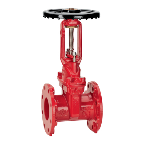
AVK 715 is a series of ductile iron, resilient seat gate valves operated by a pneumatic
actuator. They are designed for applications in clean water, waste water or sewage.
Face to face values are according to EN 558, series 3 (BS), 14 and 15.

Page 2 of 12
Copyright © AVK Holding A/S, original version, rev. 2, 30-Oct-2019
1. AVK series 715 exploded view

Page 3 of 12
Copyright © AVK Holding A/S, original version, rev. 2, 30-Oct-2019
2. AVK series 715 parts list
Item Description Material
1 Valve body Ductile iron, GJS 500-7
2 Wedge shoe PA
3 Wedge Ductile iron, GJS 500-7
4 Wedge rubber NBR
5 Wedge nut Brass CW626N
6 Lock pin Stainless steel, 1.4301
7 Split pin Stainless steel, A4
8 Stem adapter, lower Stainless steel, 1.4301
9 Set screw Stainless steel, A4
10 Washer PE
11 Bonnet gasket NBR
12 Bonnet Ductile iron, GJS 500-7
13 Bonnet bolt Stainless steel, A2-70
14 O-ring NBR
15 Nut, stuffing box - gland flange Stainless steel
16 Washer Stainless steel
17 Nut, actuator - stuffing box Stainless steel
18 Washer Stainless steel
19 Gland flange Ductile iron, GJS 500-7
20 Gasket NBR
21 Bolt, gland flange - bonnet Stainless steel
22 Wiper ring NBR
23 Shaft seal NBR
24 Spacer ring in shaft seal PE
25 Stuffing box Stainless steel
26 Bolt, stuffing - gland flange Stainless steel
27 Stud bolt, actuator - stuffing box Stainless steel
28 Actuator rod Stainless steel
29 Pneumatic actuator Festo DLP Copac
30 Solenoid valve, 5/2 Festo VSNC-FC-M52-MD-G14-F8-1B2

Page 4 of 12
Copyright © AVK Holding A/S, original version, rev. 2, 30-Oct-2019
3. Table of contents
1. AVK series 715 exploded view ........................................................................................... 2
2. AVK series 715 parts list..................................................................................................... 3
3. Table of contents ................................................................................................................ 4
4. Principle of operation .......................................................................................................... 5
5. Health and safety at work ................................................................................................... 5
6. Receiving and storage ........................................................................................................ 5
6.1 Unloading..................................................................................................................... 5
6.2 Inspection and storage................................................................................................. 6
7. Installation and commissioning ........................................................................................... 6
7.1 Installation.................................................................................................................... 6
7.2 Pneumatic actuator cylinder......................................................................................... 7
7.3 Pressure test ................................................................................................................ 7
8. Application hazards............................................................................................................. 7
9. Operation and maintenance................................................................................................ 7
9.1 Operation ..................................................................................................................... 8
9.2 Maintenance................................................................................................................. 8
9.3 Replace stuffing box shaft seal .................................................................................... 8
9.4 Replace Festo actuator piston seal and O-rings.......................................................... 9
10. Decommissioning................................................................................................................ 9
11. Trouble shooting ............................................................................................................... 10
12. Recommended spare parts............................................................................................... 11

Page 5 of 12
Copyright © AVK Holding A/S, original version, rev. 2, 30-Oct-2019
4. Principle of operation
The valve is an ordinary gate valve with a wedge completely encapsulated in rubber that
provides the soft seal. However, instead of having a rotating stem providing the vertical
movement a pneumatic cylinder is fitted. A 5/2 solenoid valve on top of the cylinder controls the
opening and closing of the valve.
5. Health and safety at work
Make sure all relevant Health and Safety issues and regulations are adhered to prior to and
during installation or maintenance work carried out on this product. It is the end user's
responsibility to ensure that safe working practices are followed at all times.
Whenever AVK’s products are installed, operated or maintained the inherent dangers of
pressurised liquids and gasses must be addressed. Before work on a valve or other piping
component is undertaken, that may involve the release of internal pressure, the valve or line
must be fully isolated, depressurised and drained prior to commencing the work. FAILURE TO
COMPLY WITH THIS MAY RESULT IN SEVERE INJURY OR DEATH.
All workers handling the product must be aware of the weight of the components or assemblies
to be handled and manipulated during installation and maintenance.
It is essential that staff undertaking these operations are adequately trained and it is the
responsibility of the end user that only trained and competent staff undertake these duties.
This manual has been designed to assist, but it cannot replace quality training in the workplace.
However, the AVK technical staff is always available and ready to answer questions relating to
specific problems that may not be covered by this manual.
AVK’s products are designed to be fit for purpose and to a high reliability standard. This
provides a safe, low risk product when used correctly for the purpose for which it was designed.
However, this assumes that the equipment is used and maintained in accordance with this
manual, and the user is advised to study it and to make it available to all staff that may need to
refer to it.
AVK cannot be held responsible for incidents arising from incorrect installation, operation or
maintenance. The responsibility for this rests wholly with the end user.
6. Receiving and storage
6.1 Unloading
Unloading must be carried out carefully. The load must be put gently to the ground without
dropping. Lifting by means of a crane or any other lifting device should only be done using the
flange holes, lifting eyes or appropriate straps. Never suspend the valve in the actuator.
If a forklift is used it shall have sufficient capacity to lift the required weight and have a valid
inspection certificate.
All workers involved in the unloading shall be able to perform their functions. They shall wear
safety boots, safety vest, safety goggles and hard hat.
All slings used for the lifting shall be of sufficient strength. A record shall document that they
have been stored under cool, dry conditions away from sunlight and chemical atmosphere, and
that they still perform according to their marked strength.

Page 6 of 12
Copyright © AVK Holding A/S, original version, rev. 2, 30-Oct-2019
6.2 Inspection and storage
Immediately after unloading the item should be inspected for compliance with specifications and
damage in shipment.
Compliance with specification check shall as a minimum comprise size, pressure class, actuator
pneumatic pressure and sealing rubber type. If solenoid valves are included the nominal voltage
should be checked.
Damage-in-shipment check shall comprise: stem, coating, seating and sealing surfaces,
corrosion on actuator and accessories and other evidence of mishandling during shipment.
Each item should be operated through one complete open-close cycle in the position and with
the air pressure and supply voltage in which it is to be installed.
Storage shall be under dry, cool conditions, away from direct sunlight and corrosive or
otherwise chemically active atmosphere.
7. Installation and commissioning
WARNING: Prior to installation make sure that all pressurized lines involved in the installation
are isolated, depressurized and drained before starting any work. Failure to do so may result in
sudden pressure release and subsequent severe injury or death.
7.1 Installation
There is no preferred flow direction, but the stem must not deviate more than 45° from vertical,
i.e. do not install on vertical pipes and do not install with horizontal actuator.
Fig. 1
Flange bolts should be tightned bolts loosely at first, then in a diagonal sequence as shown on
fig. 2 to ensure flanges are pulled in parallel to each other. Finally, tighten bolts to torque levels
according to information from gasket manufacturer.
Fig. 2
Table 1, Bolt size
DN Bolt size No. of bolts
mm PN 10 PN 16 PN 10 PN 16
40 M16 M16 4 4
50 M16 M16 4 4
65 M16 M16 4 4
80 M16 M16 8 8
100 M16 M16 8 8
150 M20 M20 8 8
200 M20 M20 8 12
250 M20 M24 12 12
300 M20 M24 12 12
350 M24 M24 16 16
400 M24 M27 16 16
Max. 45° Max. 45°

Page 7 of 12
Copyright © AVK Holding A/S, original version, rev. 2, 30-Oct-2019
During installation in the pipeline make sure that all connecting flanges are aligned and parallel
to each other.
Make sure the gasket design and material is fit for the operating conditions (medium, pressure,
temperature, etc.).
The flanges must be clean and free from grease to achieve full sealing. Place the valve and
gaskets between the pipe flanges, and insert the bolts.
7.2 Pneumatic actuator cylinder
Connect the actuator solenoid valve to an air supply system and adjust the supply pressure to
6-8 bar. Compressed air quality should be acc. to ISO8573-1:2010 [7:4:4].
The solenoid valve is a 5/2 type and comes with two coils, one for 230VAC/50-60Hz and one for
24 VDC. Make sure to select the correct coil for your voltage and also the correct gasket
between terminal box and coil as this gasket is connected to the supply voltage and equipped
with LEDs that light up when the solenoid is energized.
An LED position indicator can be fitted on the outside of the cylinder. It is powered by 24 VDC.
Fig. 3, position indicator wiring diagram
7.3 Pressure test
After installation, perform a pressure test on the piping system. The valve is designed to resist a
test pressure of 1.5 x PN.
8. Application hazards
Do not install closer than 5 pipe diameters from tees, bends or other irregularities in the
piping system as these can cause disturbing turbulence that can damage the valve over time
Do not use with sludge or slurry
Do not use if the content of suspended solids exceeds 8%
Unless properly isolated the valve should not be installed in applications where the ambient
temperature can reach values below the freezing point of the liquid
Do not install in drinking water applications as it is not approved for this
Do not use with flammable liquids
Flow speed must not exceed 3 m/s
9. Operation and maintenance
WARNING: Prior to any maintenance work that requires disassembly make sure that the
pressurized line involved is isolated, depressurized and drained before starting any
disassembly. Failure to do so may result in sudden pressure release and subsequent severe
injury or death.
In case the work includes the pneumatic actuator the air supply should be shut off and the
actuator depressurized.

Page 8 of 12
Copyright © AVK Holding A/S, original version, rev. 2, 30-Oct-2019
9.1 Operation
The valve is opened and closed by switching the solenoid valve. Be careful not to operate it in a
manner that makes it close too quickly and cause water hammer.
In case water hammer occurs the moving of the cylinder can be slowed by adjusting the
throttles in the outlet from the solenoid valve.
9.2 Maintenance
During normal operation no maintenance is necessary.
9.3 Replace stuffing box shaft seal
The seal consists of three identical U-form rubber lip seals (23) and a wiper ring (22) mounted in
series. The middle rubber seal ring has a spacer ring (24) for support.
Fig. 4, stuffing box
1. Isolate the valve and release pressure in the piping system
2. Remove the hot melt seal to uncover and unscrew the bonnet bolts and lift off the
complete bonnet assembly, including wedge and actuator
3. Unscrew the stem adaptor set screw (9) and unscrew the wedge-to-stem adapter from
the actuator rod (28)
4. Unscrew the four nuts (17) holding the actuator and separate the actuator from the
bonnet assembly
5. Unscrew the two bolts (26) holding the stuffing box
6. Press the old seal rings out of the stuffing box with a screwdriver or similar; note that the
seals will be destroyed in this process
7. Insert new seals by pressing them into the stuffing box
a. Use a ring mandrel Ø34/43 mm for DN 65-150 and Ø41/47 mm for DN 200-400
b. Make sure the opening in the U-form is facing outward as shown on fig. 4
c. Be sure to fit the spacer ring (24) in the no. 2 seal ring
d. Replace the flat gasket (20).
8. Assemble in reverse sequence
9. Tighten the bonnet bolts to approx. 20 to 30 Nm following a diagonal sequence as
shown for an 8 bolt example on fig. 5
10. Repeat step 9 with the torque wrench set to 50 Nm

Page 9 of 12
Copyright © AVK Holding A/S, original version, rev. 2, 30-Oct-2019
11. Reseal the bolt heads with hot melt glue
Fig. 5, bolt tightening sequence
9.4 Replace Festo actuator piston seal and O-rings.
1. Isolate the valve from the piping system and de-pressurize; failure to do this can result in
the valve opening suddenly and violently when the actuator is disassembled
2. Disconnect the actuator from electrical- and air supply
3. Remove the four socket head bolts holding the endcap to the cylinder
4. Lift off the cylinder carefully and in a straight line until it is free of the piston
5. Replace O-rings and seals
6. Apply fresh grease to seals and O-rings
7. Install the cylinder over the piston and end cap
8. Apply locking agent to the threads before fitting the bolts
10. Decommissioning
When decommissioning the valve it should be disposed of according to local regulations and in
a way that allows as much recycling of materials as possible.
The valve contains no hazardous materials.

Page 10 of 12
Copyright © AVK Holding A/S, original version, rev. 2, 30-Oct-2019
11. Trouble shooting
Symptom: Valve leaks
Cause: Damaged wedge rubbe
r
Cure: Replace wedge
Symptom: Wedge rubber eroded
Cause: Flow speed too high
Cure: Reduce flow speed to below 3 m/s
Symptom: Wedge rubber eroded
Cause: Turbulence
Cure: Install valve so that it upstream has at least 5 pipe diameters unrestricted with
no tees or bends or other disturbances
Symptom: Valve does not operate
Cause:
A
ctuator air supply missing or inadequate
Cure: Check and re-establish air supply; adjust air pressure to 6-8 ba
r
Symptom: Valve does not operate
Cause:
A
ctuator seals worn or cracked
Cure: Replace seals and O-rings
Symptom:
A
ctuator stuck
Cause: Poor quality of compressed ai
r
Cure: Clean solenoid valve and actuator. Install air filters and check the air quality to
be acc. to ISO 8573-1:2010 [7:4:4]
Symptom: Water hamme
r
Cause: Valve closes too quickly
Cure:
A
djust throttles on the solenoid valve outlet
Symptom: Leak around bottom of actuato
r
Cause: Stuffing box shaft seals worn or cracked
Cure: Replace shaft seals

Page 11 of 12
Copyright © AVK Holding A/S, original version, rev. 2, 30-Oct-2019
12. Recommended spare parts
Only genuine AVK and Festo spare parts should be used. AVK accepts no responsibility for
damage caused by failing non-AVK parts.
Spare parts are normally not needed as the valve is designed to operate without maintenance
for its entire lifetime. However, to make sure that it can be brought back to service in case of an
unexpected malfunction following spare parts can be kept in stock:
1. One set of stuffing box seals, ref. chapter 9.3, fig. 4, consisting of three lip seals (19), a
spacer ring (20), a wiper ring (18), a flat gasket (17) and an O-ring (25)
Ref.nos. are:
DN 65-150 715-150-12000
DN 200 715-200-12000
DN 250-300 715-300-12000
2. One set of seals and O-rings for the Festo actuator cylinder
a. DN 65-125, ref.no. 715-100-15000 (DPS-125)
b. DN 150 ref.no. 715-150-15000 (DPS-160)
Item Designation Qty
1 Rod seal 32x45x11.5 1
2 O-ring 1x1.5 2
3 O-ring 117x4 (152x4) 2
4 Lip seal 125x110x10 (160x145x10) 2
5 O-ring 20x2 (25x2) 1
6 Guideband 125 (160) 1
7 Grease 2
8 Thread lock 1

Page 12 of 12
Copyright © AVK Holding A/S, original version, rev. 2, 30-Oct-2019
c. DN 200, ref.no. 715-200-15000 (DPS-200)
Item Designation Qty
1 Rod seal 40x50x11.5 1
2 O-ring 194x4 2
3 Lip seal 200x180x14 2
4 Guide ring 200 1
5 O-ring 25x2.5 1
6 Grease 2
7 Thread lock 1
d. DN 250-300, ref.no. 715-300-15000 (DPS-320)
Item Designation Qty
1 Rod seal 40x50x11.5 1
2 O-ring 12x2.5 2
3 O-ring 10x1 4
4 O-ring 250x4.5 2
5 O-ring 32x2.5 1
6 O-ring 37x2.5 1
7 Lipseal 320x295x19 2
8 Guideband 320 1
9 Grease 2
10 Thread lock 1
Table of contents
Other AVK Control Unit manuals

AVK
AVK 41 Series Instruction manual

AVK
AVK 869 Series User manual

AVK
AVK 41 Series Troubleshooting guide

AVK
AVK 41 Series User manual

AVK
AVK 145 Series User manual

AVK
AVK 41 Series User manual

AVK
AVK 816 Series Manual

AVK
AVK 54 Series Instruction manual

AVK
AVK 02 Series User manual

AVK
AVK ACMO 879 Series Instruction manual

AVK
AVK 820 SERIES Installation and operating instructions

AVK
AVK 764 Series User manual

AVK
AVK 641 Series User manual

AVK
AVK 854 series User manual

AVK
AVK ACMO 879 Series Instruction manual

AVK
AVK 57/46 Series Instruction manual

AVK
AVK 879 Series Instruction manual

AVK
AVK 41 Series User manual

AVK
AVK 756 Series Instruction Manual